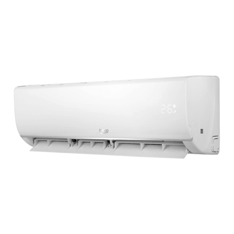
Beko BEVPI 091 User manual

Split-type room
air conditioner
Installation Manual
BEVPI 090 BEVPI 091 BEVPI 120 BEVPI 121
BEVPI 180 BEVPI 181 BEVPI 240 BEVPI 241
EN BG

Please read this user manual first!
Dear Customer,
Thank you for preferring a Beko product. We hope that you get the best results from
your product which has been manufactured with high quality and state-of-the-art
technology. Therefore, please read this entire user manual and all other accompanying
documents carefully before using the product and keep it as a reference for future
use. If you handover the product to someone else, give the user manual as well. Follow
all warnings and information in the user manual.
Meanings of the symbols
Following symbols are used in the various section of this manual:
C
Important information or useful hints
about usage.
A
Warning for hazardous situations with
regard to life and property.
Risk of fire/flammable
materials.
This symbol shows that this
appliance used a flammable
refrigerant. If the refrigerant
is leaked and exposed to an
external ignition source, there
is a risk of fire. (For the unit
adopts R32/R290 Refrigerant
only)
This product has been produced in environmentally friendly, modern facilities
Complies with the WEEE Regulation. Does not contain PCB.

Splt-type room ar condtoner / Installaton Manual 3 / 128 EN
CONTENTS
1 Safety nstructons 4
2 Accessores 8
3 Installaton summary - ndoor unt 11
4 Unt parts 13
5 Indoor unt nstallaton 14
5.1 Installaton nstructons – ndoor. . . . . . . . . . . . . . . . . . . . . . . . . . . . . . . . . . . . . . . . . . . . . . . . . . . . . . . . . . . . . . . . . . 14
6 Outdoor unt nstallaton 28
6.1 Installaton nstructons – outdoor unt . . . . . . . . . . . . . . . . . . . . . . . . . . . . . . . . . . . . . . . . . . . . . . . . . . . . . . . . . . . 28
7 Refrgerant ppng connecton 37
7.1 Note on ppe length . . . . . . . . . . . . . . . . . . . . . . . . . . . . . . . . . . . . . . . . . . . . . . . . . . . . . . . . . . . . . . . . . . . . . . . . . . . . . . . 37
7.2 Connecton nstructons – refrgerant ppng . . . . . . . . . . . . . . . . . . . . . . . . . . . . . . . . . . . . . . . . . . . . . . . . . . . . . 37
7.3 Instructons for connectng ppng to ndoor unt. . . . . . . . . . . . . . . . . . . . . . . . . . . . . . . . . . . . . . . . . . . . . . . . . 41
7.4 Instructons for connectng ppng to outdoor unt . . . . . . . . . . . . . . . . . . . . . . . . . . . . . . . . . . . . . . . . . . . . . . . 42
8 Ar evacuaton 44
8.1 Preparatons and precautons . . . . . . . . . . . . . . . . . . . . . . . . . . . . . . . . . . . . . . . . . . . . . . . . . . . . . . . . . . . . . . . . . . . . 44
8.2 Evacuaton nstructons. . . . . . . . . . . . . . . . . . . . . . . . . . . . . . . . . . . . . . . . . . . . . . . . . . . . . . . . . . . . . . . . . . . . . . . . . . . 44
9 Electrcal and gas leak checks 48
9.1 Electrcal safety checks . . . . . . . . . . . . . . . . . . . . . . . . . . . . . . . . . . . . . . . . . . . . . . . . . . . . . . . . . . . . . . . . . . . . . . . . . . . 48
9.2 Gas leak checks . . . . . . . . . . . . . . . . . . . . . . . . . . . . . . . . . . . . . . . . . . . . . . . . . . . . . . . . . . . . . . . . . . . . . . . . . . . . . . . . . . . 49
10Test run 50
10.1 Before test run. . . . . . . . . . . . . . . . . . . . . . . . . . . . . . . . . . . . . . . . . . . . . . . . . . . . . . . . . . . . . . . . . . . . . . . . . . . . . . . . . . . . 50
10.2 Test run nstructons . . . . . . . . . . . . . . . . . . . . . . . . . . . . . . . . . . . . . . . . . . . . . . . . . . . . . . . . . . . . . . . . . . . . . . . . . . . . . 50
11 European dsposal gudelnes 52
12 Installaton nstructons 53
12.1 F-Gas nstructon. . . . . . . . . . . . . . . . . . . . . . . . . . . . . . . . . . . . . . . . . . . . . . . . . . . . . . . . . . . . . . . . . . . . . . . . . . . . . . . . . . 53
13 Informaton servcng 54

4 / 128 EN Splt-type room ar condtoner / Installaton Manual
Read safety precautons before nstallaton
Incorrect nstallaton due to gnorng nstructons can cause serous
damage or njury.
The serousness of potental damage or njures s classfed as
Warnng.
Warning
•Do not modfy the length of the power supply cord or use an
extenson cord to power the unt. Do not share the electrcal outlet
wth other applances. Improper or nsuffcent power supply can
cause fre or electrcal shock.
•When connectng refrgerant ppng, do not let substances or gases
other than the specfed refrgerant enter the unt. The presence
of other gases or substances wll lower the unt’s capacty, and can
cause abnormally hgh pressure n the refrgeraton cycle. Ths can
cause exploson and njury.
•Do not allow chldren to play wth the ar condtoner. Chldren must
be supervsed around the unt at all tmes.
•Installaton must be performed by an authorzed dealer or specalst.
Defectve nstallaton can cause water leakage, electrcal shock, or
fre.
•Installaton must be performed accordng to the nstallaton
nstructons. Improper nstallaton can cause water leakage,
electrcal shock, or fre.
(In North Amerca,nstallaton must be performed n accordance
wth the requrement of NEC and CEC by authorzed personnel only.)
1 Safety nstructons

Splt-type room ar condtoner / Installaton Manual 5 / 128 EN
•Contact an authorzed servce techncan for repar or mantenance
of ths unt.
•Only use the ncluded accessores, parts, and specfed parts for
nstallaton. Usng non-standard parts can cause water leakage,
electrcal shock, fre, and can cause the unt to fal.
•Install the unt n a frm locaton that can support the unt’s weght.
If the chosen locaton cannot support the unt’s weght, or the
nstallaton s not done properly, the unt may drop and cause
serous njury and damage.
•For all electrcal work, follow all local and natonal wrng standards,
regulatons, and the Installaton Manual. You must use an
ndependent crcut and sngle outlet to supply power. Do not
connect other applances to the same outlet. Insuffcent electrcal
capacty or defects n electrcal work can cause electrcal shock or
fre.
•For all electrcal work, use the specfed cables. Connect cables
tghtly, and clamp them securely to prevent external forces from
damagng the termnal. Improper electrcal connectons can
overheat and cause fre, and may also cause shock.
•All wrng must be properly arranged to ensure that the control board
cover can close properly. If the control board cover s not closed
properly, t can lead to corroson and cause the connecton ponts
on the termnal to heat up, catch fre, or cause electrcal shock.
•In certan functonal envronments, such as ktchens, server rooms,
etc., the use of specally desgned ar-condtonng unts s hghly
recommended.
•If the supply cord s damaged, t must be replaced by the
manufacturer, ts servce agent or smlarly qualfed persons n
order to avod a hazard.
1 Safety nstructons

6 / 128 EN Splt-type room ar condtoner / Installaton Manual
1 Safety nstructons
•Ths applance can be used by chldren aged from 8 years and above
and persons wth reduced Physcal, sensory or mental capabltes
or lack of experence and knowledge f they have been gven
supervson or nstructon concernng use of the applance n a safe
way and understand the hazards nvolved. Chldren shall not play
wth the applance. Cleanng and user mantenance shall not be
made by chldren wthout supervson.
1. The applance shall be stored n a room wthout contnuously
operatng gnton sources (for example: open flames, an
operatng gas applance or an operatng electrc heater)
2. Do not perce or burn.
3. Applance shall be stored n a well -ventlated area where the
room sze corresponds to the room area as specfc for operaton.
4.Be aware that refrgerants may not contan an odour.
C
Note
Clause 1 to 4 are requred for the unts adopt R32/R290
Refrgerant
Warning
•For unts that have an auxlary electrc heater, do not nstall the unt
wthn 1 meter (3 feet) of any combustble materals.
•Do not nstall the unt n a locaton that may be exposed to
combustble gas leaks. If combustble gas accumulates around the
unt, t may cause fre.
•Do not operate your ar condtoner n a wet room such as a bathroom
or laundry room. Too much exposure to water can cause electrcal
components to short crcut.

Splt-type room ar condtoner / Installaton Manual 7 / 128 EN
•The product must be properly grounded at the tme of nstallaton,
or electrcal shock may occur.
•Install dranage ppng accordng to the nstructons n ths manual.
Improper dranage may cause water damage to your home and
property.
C
Note about fluorinated gasses
1. Ths ar-condtonng unt contans fluornated gasses.
For specfc nformaton on the type of gas and the
amount, please refer to the relevant label on the unt
tself.
2. Installaton, servce, mantenance and repar of ths unt
must be performed by a certfed techncan.
3. Product unnstallaton and recyclng must be performed
by a certfed techncan.
4.If the system has a leak-detecton system nstalled, t
must be checked for leaks at least every 12 months.
5. When the unt s checked for leaks, proper record-
keepng of all checks s strongly recommended.
1 Safety nstructons

8 / 128 EN Splt-type room ar condtoner / Installaton Manual
The ar condtonng system comes wth the followng accessores. Use all of the nstallaton parts and
accessores to nstall the ar condtoner. Improper nstallaton may result n water leakage, electrcal
shock and fre, or cause the equpment to fal.
Name Shape Quantity
Mountng plate 1
Clp anchor 5
Mountng plate fxng screw
ST3.9 X 25 5
Remote controller 1
Fxng screw for remote
controller holder ST2.9 x 10 2
Optonal Parts
Remote controller holder 1
Dry battery AAA.LR03 2
2 Accessores

Splt-type room ar condtoner / Installaton Manual 9 / 128 EN
2 Accessores
Name Shape Quantity
Seal
1
(for coolng & heatng models
only)
Dran jont
User manual
Split-type room
air conditioner
User Manual
EN
1
Installaton manual 1
Remote controller llustraton
Air conditioner
Remote control illustration
EN
1
Connect ng ppe assembly
Lqud sde Ø6.35 (1/4n)
Parts you must purchase.
Consult the dealer about the
ppe sze.
Ø9.52 (3/8n)
Gas sde
Ø9.52 (3/8n)
Ø12.7 (1/2n)
Ø16 (5/8n)

10 / 128 EN Splt-type room ar condtoner / Installaton Manual
A
Warnng:
Applance shall be stored n a well -ventlated area where
the room sze corresponds to the room area as specfec for
operaton.
For R32 frgerant models:
Applance shall be nstalled, operated and stored n a room
wth a floor area larger than 4m2.
Applance shall not be nstalled n an unvertlated space, f
that space s smaller than 4m2.
For R290 refrgerant models, the mnmum room sze
needed:
<=9000Btu/h unts: 13m2
>9000Btu/h and <=12000Btu/h unts: 17m2
>12000Btu/h and <=18000Btu/h unts: 26m2
>18000Btu/h and <=24000Btu/h unts: 35m2
2 Accessores

Splt-type room ar condtoner / Installaton Manual 11 / 128 EN
12cm
(4.75n)
15cm (5.9n)
12cm
(4.75n)
2.3m (90.55n)
Select Installaton Locaton
(Page 14)
Determne Wall Hole Poston
(Page 15)
3
Attach Mountng Plate
(Page 15)
Drll Wall Hole
(Page 16)
3 Installaton summary - ndoor unt

12 / 128 EN Splt-type room ar condtoner / Installaton Manual
5
Connect Ppng
(Page 37)
Connect Wrng
(Page 22)
Prepare Dran Hose
(Page 18)
Wrap Ppng and Cable
(Page 25)
Mount Indoor Unt
(Page 26)
3 Installaton summary - ndoor unt

Splt-type room ar condtoner / Installaton Manual 13 / 128 EN
1
2
3
4
11
10
9
5
8
7
6
1. Wall Mountng Plate
2. Power Cable (Some Unts)
3. Dranage Ppe
4. Sgnal Cable
5. Refrgerant Ppng
6. Remote Holder
7. Remote Control (Some Unts)
8. Outdoor Unt Power Cable (Some Unts)
9. Functonal Flter (On Front of Man Flter -
Some Unts)
10. Louver
11. Front Panel
C
Note:
Illustratons n ths manual are for explanatory purposes. The actual shape of your ndoor
unt may be slghtly dfferent. The actual shape shall preval.
4 Unt parts

14 / 128 EN Splt-type room ar condtoner / Installaton Manual
5.1 Installaton nstructons – ndoor
Prior to installation
Before nstallng the ndoor unt, refer to the label on the product box to make sure that the model
number of the ndoor unt matches the model number of the outdoor unt.
Step 1: Select nstallaton locaton
Before nstallng the ndoor unt, you must choose an approprate locaton. The followng are
standards that wll help you choose an approprate locaton for the unt.
Proper nstallaton locatons meet the followng standards:
•Good ar crculaton
•Convenent dranage
•Nose from the unt wll not dsturb other people
•Frm and sold—the locaton wll not vbrate
•Strong enough to support the weght of the unt
•A locaton at least one meter from all other electrcal devces (e.g., TV, rado, computer)
DO NOT nstall unt n the followng locatons:
•Near any source of heat, steam, or combustble gas
•Near flammable tems such as curtans or clothng
•Near any obstacle that mght block ar crculaton
•Near the doorway
•In a locaton subject to drect sunlght
5 Indoor unt nstallaton

Splt-type room ar condtoner / Installaton Manual 15 / 128 EN
C
Note about wall hole:
If there s no fxed refrgerant ppng:
Whle choosng a locaton, be aware that you should leave ample room for a wall hole
(see Drll wall hole for connectve ppng step) for the sgnal cable and refrgerant
ppng that connect the ndoor and outdoor unts. The default poston for all ppng
s the rght sde of the ndoor unt (whle facng the unt). However, the unt can
accommodate ppng to both the left and rght.
Refer to the followng dagram to ensure proper dstance from walls and celng:
15cm (5.9n) or more
12cm (4.75n)
or more
12cm (4.75n)
or more
2.3m (90.55n) or more
Fg. 5.1
Step 2: Attach mountng plate to wall
The mountng plate s the devce on whch you wll mount the ndoor unt.
1. Remove the screw that attaches the mountng plate to the back of the ndoor unt.
2. Place the mountng plate aganst the wall n a locaton that meets the standards n the Select
Installaton Locaton step. (See Mountng Plate Dmensons for detaled nformaton on mountng
plate szes.)
3. Drll holes for mountng screws n places that:
•have studs and can support the weght of the unt
•correspond to screw holes n the mountng plate
4. Secure the mountng plate to the wall wth the screws provded.
5. Make sure that mountng plate s flat aganst the wall.
5 Indoor unt nstallaton

16 / 128 EN Splt-type room ar condtoner / Installaton Manual
5 Indoor unt nstallaton
C
Note for concrete or brick walls:
If the wall s made of brck, concrete, or smlar materal, drll 5mm-dameter (0.2n-
dameter) holes n the wall and nsert the sleeve anchors provded. Then secure the
mountng plate to the wall by tghtenng the screws drectly nto the clp anchors.
Step 3: Drll wall hole for connectve ppng
You must drll a hole n the wall for refrgerant ppng, the dranage ppe, and the sgnal cable that wll
connect the ndoor and outdoor unts.
1. Determne the locaton of the wall hole based on the poston of the mountng plate. Refer to
Mountng Plate Dmensons on the next page to help you determne the optmal poston. The
wall hole should have a 65mm (2.5n) dameter at least, and at a slghtly lower angle to facltate
dranage.
2. Usng a 65-mm (2.5n) core drll, drll a hole n the wall. Make sure that the hole s drlled at a slght
downward angle, so that the outdoor end of the hole s lower than the ndoor end by about 5mm to
7mm (0.2-0.275n). Ths wll ensure proper water dranage. (See Fg. 5.2)
3. Place the protectve wall cuff n the hole. Ths protects the edges of the hole and wll help seal t
when you fnsh the nstallaton process.
A
Warning
When drllng the wall hole, make sure to avod wres,
plumbng, and other senstve components.
Wall
Fg. 5.2
OutdoorIndoor
5-7 mm
(0.2-0.3n)

Splt-type room ar condtoner / Installaton Manual 17 / 128 EN
Mounting plate dimensions
Dfferent models have dfferent mountng plates. In order to ensure that you have ample room to
mount the ndoor unt, the dagrams to the rght show dfferent types of mountng plates along wth
the followng dmensons:
•Wdth of mountng plate
•Heght of mountng plate
•Wdth of ndoor unt relatve to plate
•Heght of ndoor unt relatve to plate
•Recommended poston of wall hole (both to the left and rght of mountng plate)
•Relatve dstances between screw holes
Correct orentaton of Mountng Plate
Indoor unt outlne
Indoor unt outlne
Rght rear wall hole
65mm (2.5n)
Rght rear wall hole
65mm (2.5n)
Left rear wall hole
65mm (2.5n)
348.4mm (13.7n)
426mm (16.8n)
101mm (4n)
192mm (7.55n)
722mm (28.45n)
802mm (31.6n)
179mm (7.05n)
232mm (9.15n)
136mm (5.35n)
128mm (5.05n)
37mm (1.45n)
43mm (1.7n)
290mm (11.4n)297mm (11.7n)
49mm (1.95n)
43mm (1.7n)
49mm (1.95n)
43mm (1.7n)
5 Indoor unt nstallaton

18 / 128 EN Splt-type room ar condtoner / Installaton Manual
Model C
Model D
Model E
Indoor unt outlne
Indoor unt outlne
Indoor unt outlne
Rght rear wall hole
65mm (2.5n)
Rght rear wall hole
65mm (2.5n)
Rght rear wall hole
65mm (2.5n)
Left rear wall hole
65mm (2.5n)
Left rear wall hole
65mm (2.5n)
517.4mm (20.37n)
553mm (21.77n)
643.6mm (25.3n)
138mm (5.45n)
219mm (8.6n)
389mm (15.3n)
172mm (6.8n)
52mm (2.05n)
965mm (38n)
34mm (1.35n)
1080mm (42.5n)
1259mm (49.55n)
257mm (10.1n)
144mm (5.65n)
300mm (11.8n)
151mm (5.95n)
174.3mm (6.85n)
76mm(3n)
53.5mm
(2.1n)
53.5mm (2.1n)
47mm (1.85n)
148.7mm
(5.85n)
332mm (13.05n)
52mm (2.05n)
58mm (2.3n)
319mm (12.55n)
335mm (13.2n)
362mm (14.25n)
57mm (2.25n)
47mm (1.85n)47mm (1.85n)
40mm (1.55n)
Step 4: Prepare refrgerant ppng
The refrgerant ppng s nsde an nsulatng sleeve attached to the back of the unt. You must prepare
the ppng before passng t through the hole n the wall. Refer to the Refrgerant Ppng Connecton
secton of ths manual for detaled nstructons on ppe flarng and flare torque requrements,
technque, etc.
1. Based on the poston of the wall hole relatve to the mountng plate, choose the sde from whch
the ppng wll ext the unt.
2. If the wall hole s behnd the unt, keep the knock-out panel n place. If the wall hole s to the sde of
the ndoor unt, remove the plastc knock-out panel from that sde of the unt. (See Fg. 5.3 ). Ths
wll create a slot through whch your ppng can ext the unt. Use needle nose plers f the plastc
panel s too dffcult to remove by hand.
5 Indoor unt nstallaton

Splt-type room ar condtoner / Installaton Manual 19 / 128 EN
Knock-out Panel
Fg. 5.3
3. Use scssors to cut down the length of the nsulatng sleeve to reveal about 15cm (6n) of the
refrgerant ppng. Ths serves two purposes:
• To facltate the Refrgerant Ppng Connecton process
• To facltate Gas Leak Checks and enable you to check for dents
4. If exstng connectve ppng s already embedded n the wall, proceed drectly to the Connect
Dran Hose step. If there s no embedded ppng, connect the ndoor unt’s refrgerant ppng to
the connectve ppng that wll jon the ndoor and outdoor unts. Refer to the Refrgerant Ppng
Connecton secton of ths manual for detaled nstructons.
5. Based on the poston of the wall hole relatve to the mountng plate, determne the necessary
angle of your ppng.
6. Grp the refrgerant ppng at the base of the bend.
7. Slowly, wth even pressure, bend the ppng towards the hole. Do not dent or damage the ppng
durng the process.
C
Note on piping angle
Refrgerant ppng can ext the ndoor unt from four dfferent angles:
•Left-hand sde
•Left rear
•Rght-hand sde
•Rght rear
Refer to Fg. 5.4 fo r detals.
5 Indoor unt nstallaton

20 / 128 EN Splt-type room ar condtoner / Installaton Manual
Fg. 5.4
A
Warning
Be extremely careful not to dent or damage the ppng
whle bendng them away from the unt. Any dents n the
ppng wll affect the unt’s performance.
Step 5: Connect dran hose
By default, the dran hose s attached to the lefthand sde of unt (when you’re facng the back of the
unt). However, t can also be attached to the rght-hand sde.
1. To ensure proper dranage, attach the dran hose on the same sde that your refrgerant ppng exts
the unt.
2. Attach dran hose extenson (purchased separately) to the end of dran hose.
3. Wrap the connecton pont frmly wth Teflon tape to ensure a good seal and to prevent leaks.
4. For the porton of the dran hose that wll reman ndoors, wrap t wth foam ppe nsulaton to
prevent condensaton.
5. Remove the ar flter and pour a small amount of water nto the dran pan to make sure that water
flows from the unt smoothly.
C
Note on drain hose placement
Make sure to arrange the dran hose accordng to Fg. 5.5.
•DO NOT knk the dran hose.
•DO NOT create a water trap.
•DO NOT put the end of dran hose n water or a contaner that wll collect water.
Plug the unused drain hole
To prevent unwanted leaks you must plug the unused dran hole wth the rubber plug provded.
5 Indoor unt nstallaton
This manual suits for next models
7
Table of contents
Languages:
Other Beko Air Conditioner manuals

Beko
Beko BX 109 C User manual

Beko
Beko RSVC09VT-I User manual

Beko
Beko BPN112H User manual

Beko
Beko BRAE 090 User manual

Beko
Beko 30925 User manual

Beko
Beko BBVHO 090 User manual

Beko
Beko BEHPGH 090 User manual

Beko
Beko Mono Split Room Air Conditioner User manual

Beko
Beko BEPN 09C User manual

Beko
Beko BSWOA 090 User manual
Popular Air Conditioner manuals by other brands

Haier
Haier HSU-09C03/U Operation manual

Toshiba
Toshiba RAS-10JKVP-E Service manual

Samsung
Samsung AC TN4PKG Series user manual

Panasonic
Panasonic CS-W14BB4P operating instructions

Nibe
Nibe BA-SVM 10-200 Series Service manual

Frigidaire
Frigidaire FAC124P1A - Compact II 12,000-BTU Room Air... use and care manual