Desa (V)TC36N(-HA) Series, (V)TC36P Quick start guide

For more information, visit www.desatech.com
WARNING: If the information in this manual is not fol-
— WHAT TO DO IF YOU SMELL GAS
• Do not touch any electrical switch; do not use any
-
DIRECT-VENT FIREPLACE
OWNER’S OPERATION AND INSTALLATION MANUAL
NATURAL GAS MODELS
(V)TC36N(-HA) SERIES
PROPANE/LP GAS MODELS
(V)TC36P(-HA) SERIES

www.desatech.com 116192-01G2
SAFETy INFORMATION
TAbLE OF CONTENTS
Safety Information ............................................... 2
Product Identication........................................... 4
Local Codes......................................................... 4
Product Features................................................. 5
Pre-Installation Preparation................................. 5
Location of Termination Cap................................ 8
Venting Installation Instructions ........................... 9
Fireplace Installation.......................................... 19
Operating Fireplace........................................... 27
Inspecting Burners............................................. 30
Cleaning and Maintenance................................ 31
Troubleshooting................................................. 33
Replacement Parts............................................ 37
Service Hints ..................................................... 37
Technical Service............................................... 37
Specications .................................................... 37
Illustrated Parts Breakdown and Parts List........ 38
Accessories ....................................................... 42
Warranty Information ...........................Back Cover
-
-
teration, service or main-
tenance can cause in-
Refer to this manual for
correct installation and
For assistance or addi-
tional information con-
-
stalled in an aftermarket,*
-
State of Massachusetts:
The installation must
the Commonwealth of
chemicals known to the State
of California to cause cancer or
-
-

www.desatech.com
116192-01G 3
This replace must be installed by a qualied (cer-
tied or licensed) service person. It has a sealed
gas combustion chamber that uses a coaxial pipe
(pipe within a pipe and having the same center)
venting system. It brings in fresh air for combus-
tion through the outer pipe and combustion gases
are exhausted through the inner pipe. If the glass
door assembly and venting pipe are not properly
seated, connected and sealed, carbon monoxide
leakage (spillage) can occur.
Early signs of
carbon monoxide poisoning resemble the u, with
headaches, dizziness or nausea. If you have these
signs, the replace may not be working properly.
Get fresh air at once! Have replace serviced.
Some people are more affected by carbon monoxide
than others. These include pregnant women, people
with heart or lung disease or anemia, those under the
inuence of alcohol and those at high altitudes.
Natural and pro-
pane/LP gas are odorless. An odor-making agent
is added to the gas. The odor helps you detect a gas
leak. However, the odor added to the gas can fade.
Gas may be present even though no odor exists.
Make certain you read and understand all warnings.
Keep this manual for reference. It is your guide to
safe and proper operation of this replace.
-
-
SAFETy INFORMATION
Continued WARNING: Do not allow fans
-
-
adults away from hot surface to
-
dren when they are in the room
1. For propane/LP replace, do not place pro-
pane/LP supply tank(s) inside any structure.
Locate propane/LP supply tank(s) outdoors.
To prevent performance problems, do not
use propane/LP fuel tank of less than 100 lb.
capacity.

www.desatech.com 116192-01G4
2. If you smell gas
• shut off gas supply
• do not try to light any appliance
• do not touch any electrical switch; do not use
any phone in your building
• immediately call your gas supplier from a
neighbor’s phone. Follow the gas supplier's
instructions
• if you cannot reach you gas supplier, call the
re department.
3. Never install the replace
• in a recreational vehicle
• in windy or drafty areas where curtains or
other combustible (ammable) objects can
make contact with the replace front
• in high trafc areas
4. Turn replace off and let cool before servicing,
installing or repairing. Only a qualied service
person should install, service or repair this
replace. Have replace inspected annually
by a qualied service person.
5. You must keep control compartments, burn-
ers and circulating air passages clean. More
frequent cleaning may be needed due to ex-
cessive lint and dust from carpeting, bedding
material, etc. Turn off the gas valve and pilot
light before cleaning replace.
6. Have venting system inspected annually by a
qualied service person. If needed, have vent-
ing system cleaned or repaired. See Cleaning
and Maintenance, page 31.
7. Do not use any solid fuels (wood, coal, paper,
cardboard, etc.) in this replace. Use only the
gas type indicated on replace nameplate.
8. This appliance, when installed, must be electri-
cally grounded in accordance with local codes
or, in the absence of local codes, with the
National Electrical Code, ANSI/NFPA 70 or
the Canadian Electrical Code, CSA C22.1.
9. Do not use replace if any part has been ex-
posed to or under water. Immediately call a
qualied service person to arrange for replace-
ment of the unit.
10. Do not operate replace if any log is broken.
11. Do not operate fireplace with glass door
removed, cracked or broken.
12. Provide adequate clearances around air
openings.
SAFETy INFORMATION
Continued
PRODUCT
IDENTIFICATION
Figure 1 - Direct-Vent Fireplace with
Millivolt Ignition
Glass
Door
Assembly
Switch Bracket for Optional
Remote and Blower
Control Valve
with Piezo
Ignitor
Log
Set
Lava
Rock
Glowing
Embers
Upper Louver
Panel
Lower
Louver
Panel
Flue Collar
Nailing
Flange
Burner
Assembly
LOCAL CODES
Install and use replace with care. Follow all local
codes. In the absence to local codes, use the cur-
rent National Fuel Gas Code ANSI Z223.1/NFPA
54* (USA) or the current CSA-B149.1 Installation
Code (Canada).
*Available from:
American National Standards Institute, Inc.
1430 Broadway
New York, NY 10018
National Fire Protection Association, Inc.
Batterymarch Park
Quincy, MA 02269

www.desatech.com
116192-01G 5
PRODUCT FEATURES
These are a few facts that can help you understand
and enjoy your direct-vent replace:
• The venting system may be routed to the out-
side of your home in several ways. It may vent
through the roof (vertical) or it may vent to an
outside/exterior wall (horizontal). The vent
pipe installation is very important to allow for
proper operation. You must follow the venting
instructions very carefully for either vertical or
horizontal applications.
• This replace may be installed in any room of
your house provided all local codes and these
installation instructions are followed.
• This replace requires a wall switch, hand-held
remote or wall thermostat (millivolt) for opera-
tion (see Accessories, page 42).
• This replace does not require electricity to
operate.
• Only the blower requires electricity if installed
and if you plan to install the blower at a later
date, do not forget to wire the outlet at the bot-
tom of the replace when framing.
• A piezo ignitor and ceramic electrode create
spark to ignite the pilot light. It does not require
any matches, batteries or any other sources of
ignition to light the pilot.
• Each time you turn on your replace, you may
notice some amount of condensation on the in-
side of the replace glass. This is normal and will
disappear after 10-20 minutes of operation.
• Your direct-vent gas replace system (replace
and venting) is a balanced and sealed gas op-
erating unit. It requires approximately 10-20
minutes of operating time before the ame
pattern stabilizes.
• Fireplaces with the sufx of -HA have been
designed to operate at altitudes of 4000 feet
and above.
PRE-INSTALLATION
PREPARATION
LOCATION AND SPACE
REQUIREMENTS
Determine the safest and most efcient location
for your DESA direct-vent replace. Make sure
that rafters and wall studs are not in the way of the
venting system. Choose a location where the heat
output is not affected by drafts, air conditioning
ducts, windows or doors. Figure 2 shows some
common locations. Be aware of all restrictions and
precautions before deciding the exact location for
your replace and termination cap.
Figure 2 - Common Fireplace Locations
Flush with a wall
Through exterior wall
enclosed in a chase
Corner
installation
Figure 3 - Fireplace Bottom Dimensions
D
RW
FW
21 1/8"
41"
When deciding the location of your replace,
follow these rules:
• Do not connect this replace venting to a chim-
ney ue serving a separate solid-fuel burning
replace or appliance.
• Due to high temperatures, do not locate this
replace in high trafc areas, windy or drafty
areas or near furniture or draperies.
• Proper clearances must be maintained.
• If your replace is to be installed directly on
carpeting, vinyl tile or any combustible mate-
rial other than wood, it must be installed on a
metal or wood panel extending the full width
and depth of the replace. See Figure 3.
• Your replace is designed to be used in zero
clearance installations. Wall or framing material
can be placed directly against any exterior sur-
face on the back, sides or top of your replace,
except where standoff spacers are integrally
attached. If standoff spacers are attached to your
replace, these spacers can be placed directly
against wall or framing material. See framing
details on page 6.
• If you plan on installing a television or enter-
tainment center recessed above your replace, it
is recommended that you maintain a minimum
18" above top of louver opening.
• When locating termination cap, it is important
to observe the minimum clearances shown in
Figure 7, page 8.
29"

www.desatech.com 116192-01G6
• If recessing into a wall, you can avoid extra
framing by positioning your replace against
an already existing framing member.
• Do not recess termination cap into a wall or
siding.
• You may paint the termination cap with 450º F
(232º C) heat-resistant paint to coordinate with
the exterior nish.
• There must not be any obstruction such as
bushes, garden sheds, fences, decks or util-
ity buildings within 24" from the front of the
termination cap.
• Do not locate termination cap where excessive
snow or ice build up may occur. Be sure to
clear vent termination area after snow falls to
prevent accidental blockage of venting system.
When using snow blowers, do not direct snow
towards vent termination area.
• For horizontal installations above 2,000 feet, it
is recommended that a 12" extension pipe be
added before starter elbow and a round hori-
zontal termination be used (see High Altitude
Installation, page 17).
CLEARANCES
Minimum clearances to combustibles for the re-
place are as follows:
*Back and sides 0"
Perpendicular walls 6"
Floor 0"
Ceiling to louver opening 42"
Front 36"
Top of Standoffs 0"
Vent (See venting instructions
for specific venting
clearances.)
Combustible material with a maximum thick-
ness of 5/8" may be ush with the top front of
replace.
* For back and sides of replace, do not pack
with insulation or other materials. 0" clear-
ance to combustible materials are for framing
purpose only.
PRE-INSTALLATION
PREPARATION
Continued
-
-
FRAMING AND FINISHING
Figure 4 shows typical framing of this replace.
Figure 5, page 7, shows framing for corner instal-
lation. All minimum clearances must be met.
For available accessories for this replace, see
Accessories on page 42. If you are using a separate
combustible mantel piece, refer to Figure 6, page
7, for proper installation height. You can install
noncombustible mantels at any height above the
replace.
Note: Noncombustible mantels may discolor!
Figure 4 - Framing Clearances for
Installation Against an Exterior Wall
36 1/8"
41 1/4"
21" Horizontal Vent
24 1/2" Vertical Vent

www.desatech.com
116192-01G 7
A
B
E
F
G
H
DC
Nailing Tabs
C
B
A
DE
FG
Top of Louver
Opening
3
2
1
4
5
6
7
Wall
Figure 5 - Framing Clearances for Corner
Installation
Mantel
Mantel from
1 14" A 16"
2 12" B 14"
3 10" C 12"
4 8" D 10"
5 6" E 8"
6 4" F 6"
7 2" G 4"
Figure 6 - Clearances for Combustible
Mantels
41"
411/4"
353/4"
15"
133/4"
681/2"
103/8"
PRE-INSTALLATION
PREPARATION
Continued
Nailing
Tabs
195/8"
195/8"

www.desatech.com 116192-01G8
Fixed
Closed Openable Fixed
Closed
V
V
V
V
VV
V
V
X
X
VX
G
G
J
F
B
B
K
N
H
I
A
N
E
L
D
B
M
A
C
B
V
V
A
G
G
B
TERMINATION CAP AIR SUPPLY INLET GAS METER RESTRICTED AREA
(TERMINATION PROHIBITED)
A = clearance above grade, veranda, porch, deck, or
balcony [*12" (30.5 cm) minimum]
B = clearance to window or door that may be opened
[6" (15 cm) min. for 10,000 Btu or less; 9" (23 cm) in US
if between 10,000 and 50,000, 12" (30 cm) in Canada
if between 10,000 and 100,000; 12" (30 cm) in US if
greater than 50,000, 36" (91 cm) in Canada if greater
than 100,000]
C = clearance to permanently closed window
[minimum 12" (30.5 cm) recommended to prevent
condensation on window]
D = vertical clearance to ventilated soffit located above the
terminal within a horizontal distance of 24" (61 cm) from
the center-line of the terminal [18" (45.7 cm) minimum]
E = clearance to unventilated soffit [12" (30.5 cm) minimum]
F = clearance to outside corner (see below)
G = clearance to inside corner (see below)
H = *not to be installed above a meter/regulator assembly
within 36" (91.4 cm) horizontally from the center line
of the regulator
I = clearance to service regulator vent outlet [*72" (182.9 cm)
minimum]
J = clearance to non-mechanical air supply inlet to building
or the combustion air inlet to any other fireplace
[6" (15 cm) min. for 10,000 Btu or less; 9" (23 cm) in US
if between 10,000 and 50,000, 12" (30 cm) in Canada
if between 10,000 and 100,000; 12" (30 cm) in US if
greater than 50,000, 36" (91 cm) in Canada if greater
than 100,000]
K = clearance to a mechanical air supply inlet [*In Canada,
6 ft. (1.83m) minimum; In US 3 ft. (91 cm) above if within
10 ft. (3 m) horizontally]
L = † clearance above paved side-walk or a paved driveway
located on public property [*84" (213.3 cm) minimum]
M = clearance under veranda, porch, deck
[*12" (30.5 cm) minimum ‡]
N = clearance above a roof shall extend a minimum of
24" (61 cm) above the highest point when it passes
through the roof surface and any other obstruction within
a horizontal distance of 18" (45.7 cm)
† vent shall not terminate directly above a side-walk or paved driveway which is located between two
single family dwellings and serves both dwellings*
‡ only permitted if veranda, porch, deck or balconey is fully open on a minimum of 2 sides beneath the floor*
* as specified in CAN/CSA B149 (.1 or .2) Installation Codes (1991) for Canada and U.S.A.
Note: Local codes or regulations may require different clearances
A = 6" (15.2 cm)
Inside Corner
V
B
E
V
B = 6" (15.2 cm)
C = Maximum depth of 48" (121.9 cm)
for recessed location
D = Minimum width for back wall of
recessed location -
Combustible - 38" (965 mm)
Noncombustible - 24" (61 cm)
E = Clearance from corner in
recessed location-
Combustible - 6" (15.2 cm)
Noncombustible - 2" (5.1 cm)
Outside Corner Recessed Location
G
H
G = 12" (30.5 cm) minimum clearance
Balcony with No Side Wall
V
J
Combustible &
Noncombustible
H = 24" (61 cm)
J = 20" (50.8 cm)
Balcony with Perpendicular Side Wall
C
D
C
Termination Clearances for Buildings with Combustible and Noncombustible Exteriors
Openable
Figure 7 - Minimum Clearances for Termination Cap
LOCATION OF TERMINATION CAP

www.desatech.com
116192-01G 9
VENTING INSTALLATION
INSTRUCTIONS
NOTICE: Read these instruc-
-
These models are tested and approved for use
with DESA (direct-vent) pipe components and
terminations.
The venting system must terminate on the outside of
the structure and can not be attached to a chimney
or ue system serving a separate solid fuel or gas
burning appliance. A direct-vent appliance must
have its own venting system. DO NOT common
vent this appliance.
These models are approved to be vented either
horizontally through an outside wall or vertically
through a roof or chase enclosure using the fol-
lowing guidelines:
• When venting system terminates horizontally
on an outside wall, you may install a standoff
if the termination cap is to be installed directly
on a combustible nish such as vinyl, wood,
stucco, etc.
• Never run the vent downward as this may
cause excessive temperatures which could
cause a re.
• Vent pipe air space clearances to combustibles
are 1" on all sides except on the horizontal
sections, which requires 2" clearance from
the top of the pipe. Where the termination cap
penetrates a combustible wall, 1" air space
clearance is required.
• Snorkel terminations are required when
minimum clearance to grade cannot be met (see
Figure 16 on page 13).
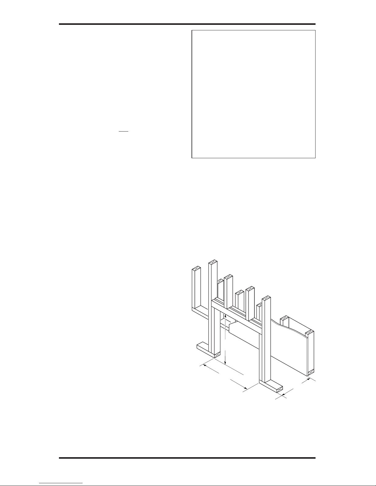
• Have replace and selected vent components on
hand to help determine the exact measurements
when elbowing or offsetting. Always use wall
restops when penetrating walls and restops
when penetrating ceilings or attic spaces.
• If using a venting conguration of only hori-
zontal venting with no vertical run, a 1/4" rise
for every 12" of run toward the termination is
required.
• For installation of replace at elevations of 4000
feet or greater, pay special attention to venting
requirement recommendations.
WARNING: Read all instruc-
Failure to do so could result in
NOTICE:Failuretofollowthesein-
NOTICE: Do not seal termination
INSTALLATION PRECAUTIONS
• Wear gloves and safety glasses for protection
• Use extreme caution when using ladders or
when on roof tops
• Be aware of electrical wiring locations in walls
and ceilings
The following actions will void the warranty on
your venting system:
• Installation of any damaged venting component
• Unauthorized modication of the venting sys-
tem (Do not cut or alter vent components)
• Installation of any component part not manu-
factured or approved by DESA
• Installation other than as instructed by these
instructions

www.desatech.com 116192-01G10
INSTALLATION PLANNING
There are two basic types of direct-vent in-
stallation:
• Horizontal Termination
• Vertical Termination
Horizontal Termination Installation
IMPORTANT: Horizontal square terminations
require only inner portion of wall restop. Hori-
zontal installations using round termination require
exterior portion of wall restop (see Figure 14,
page 12).
1. Set the replace in its desired location and deter-
mine the route your horizontal venting will take.
Do not secure the replace until all venting has
been installed. Some installations require sliding
the replace in and out of position to make nal
venting connections. Figures 14 through 18 on
pages 12 through 14 show different congura-
tions for venting with horizontal termination that
will help you decide which application best suits
your installation. Check to see if wall studs or
roof rafters are in the path of your desired vent-
ing route. If they are, you may want to adjust the
location of the replace.
2. Direct vent pipe sections and components are
designed with special twist-lock connections.
Twist-Lock Procedure: The female ends of the
pipes have locking lugs (indentations). These
lugs will slide straight into matching slots on
the male ends of adjacent pipes. Push pipe sec-
tions together and twist one section clockwise
approximately one-quarter turn until the sections
are fully locked (see Figure 8). Note: Horizontal
runs of vent must be supported every three feet.
Use wall straps for this purpose.
3. Use a 45° elbow to connect venting system
to replace ue collar. The elbow is designed
to be twist-locked onto the flue collar as
described in step 2. IMPORTANT: Do not
attempt to alter the conguration of the elbow
by cutting, twisting, bending, etc.
4. Assemble the desired combination of pipe and
elbows to the replace ue collar. If there are
long portions of venting run, pre-assembled
pipe sections may be installed as subassem-
blies for convenience.
VENTING INSTALLATION
INSTRUCTIONS
Continued
Figure 8 - Vent Pipe Connections
Female
Locking Lugs
Male
Slots
(Framing
Detail)
10
3
/
4
"
10
3
/
4
" Inside Framing
10
3
/
4
"
8
1
/
2
"
Vent
O
pening
Combustible Wall
Vent Opening
Noncombustible Wall
Figure 9 - Vent Opening Requirements
Center of
Hole
5. Carefully determine the location where the vent
pipe assembly will penetrate the outside wall.
The center of the hole should line up with the
center-line of the horizontal vent pipe. Mark the
wall for a 10 3/4" x 10 3/4" square hole. Cut and
frame the square hole in the exterior wall where
the vent will be terminated. If the wall being
penetrated is constructed of noncombustible
material, such as masonry block or concrete,
a 8 1/2" hole with zero clearance is acceptable
(see Figure 9).

www.desatech.com
116192-01G 11
VENTING INSTALLATION
INSTRUCTIONS
Continued
WARNING: Do not recess
6. Position the
horizontal vent cap in the center of the 8 1/2"
round hole and attach to the exterior wall with
four wood screws provided. Before attaching
the vent cap to exterior wall, run a bead of
non-hardening mastic (pliable sealant) around
the outside edges to make a seal between it and
the outside wall. Note: The four wood screws
provided should be replaced with appropriate
fasteners for stucco, brick, concrete or other
types of sidings.
For vinyl siding,
stucco or wood exteriors, a siding standoff may
be installed between the vent cap and exterior
wall. The siding standoff prevents excessive
heat from damaging the siding materials.
Siding material must be cut to accommodate
standoff. Bolt the vent cap to the standoff. Ap-
ply non-hardening mastic around outside edge
of standoff. Position the standoff/cap assembly
in the center of the 10 3/4" square hole and attach
to exterior wall with wood screws provided (see
Figure 11). The siding standoff must sit ush
against the exterior fascia material.
7. Slide the wall
restop over the vent pipe before connecting
horizontal run to vent cap (see Figure 12).
8. Carefully move replace, with vent assembly
attached, toward wall and insert vent pipe
into horizontal termination. The pipe overlap
should be a minimum of 11/4" (see Figure 13,
page 12).
9. Slide wall
restop against interior wall surface and attach
with screws provided. See Figure 13, page 12,
for horizontal termination details.
10. Place replace into position and shim with
noncombustible material if needed. Nail or
screw side anges to framing to secure unit in
place. IMPORTANT: Make sure replace is
level before securing. If replace is not level
it will not work properly.
Figure 10 - Installing Horizontal Vent Cap
(Noncombustible Exterior)
Wood Screw
Vent Cap
Figure 11 - Installing Siding Standoff
(Combustible Exterior Wall)
Cut Siding Away to
Fit Standoff
Wood
Screw
Screws
Standoff
Vent
Cap
Apply Mastic
to All Four Sides
Vent Cap
(Horizontal
Termination)
Interior Wall
Surface
Wall
Firestop
Horizontal
Vent Pipe
Figure 12 - Connecting Vent Cap with
Horizontal Vent Pipe
Screw

www.desatech.com 116192-01G12
VENTING INSTALLATION
INSTRUCTIONS
Continued
Figure 13 - Typical Horizontal
Termination Cap Mounting with
Additional Siding Standoff Installed
Siding Standoff
Screws
High Wind
Termination
Apply
Mastic to
Outside
Edge of
Standoff
Exterior Wall with Vinyl Siding
10 3/4" x 10 3/4"
Framed Opening
Maintain 1"
Minimum Air
Space Around
Outer Pipe When
Penetrating a Wall
Minimum Pipe
Overlap 11/4"
Wall
Firestop
Direct-Vent
Pipe
Figures 14 through 18 show different congura-
tions and alternatives for venting with horizontal
termination. Each gure includes a chart with
critical minimum and maximum dimensions which
MUST be met. IMPORTANT: If using a venting
conguration of only horizontal venting with no
vertical run, a 1/4" rise for every 12" of run toward
the termination is required.
NOTICE: Do not seal termination
WARNING: Never run vent
downward as this may cause
-
GROUND FLOOR INSTALLATION
Recommended Applications:
• Installation using cabinet surrounds
• Through the wall using round or square termina-
tion (up to 12" horizontal pipe)
• NOT FOR CORNER INSTALLATION
Horizontal
High Wind
Square
Termination
Wall Firestop
45° Elbow
Figure 14 - Horizontal Termination
Conguration for Square or Round
Terminations
45° Elbow
Wall
Firestop
Horizontal
Round
Termination
Exterior Portion
of Wall Firestop
(Round
Termination
Only)
Adjustable
Pipe 12" Max.
Round
Termination
32 3/4" min. 17" max.
* If installing this replace at altitudes of
4000 feet and above, it is recommended
that an additional vertical height of 6" be
added to the vent system.

www.desatech.com
116192-01G 13
CORNER INSTALLATION
Recommended Applications:
• Corner ground oor installation
• Ground oor installation where pipe vents horizon-
tally through wall (over 12" horizontal pipe)
• Basement installation where one foot clearance
from ground to termination is possible
VENTING INSTALLATION INSTRUCTIONS
Continued
Figure 15 - Horizontal Termination Conguration for Corner Installation Using One
90° Elbow
Square
Termination
Wall
Firestop
Not to Exceed (H) Limits
As Required
for (V), See
Chart for
Pipe Section
Required
45° Elbow
90° Elbow
90° Elbow
Square
Termination
Wall
Firestop
45° Elbow
12" Min.
*43 1/2" min. None 30" max.
54 1/2" min. 1 ft. 48" max.
66 1/2" min. 2 ft. 60" max.
78 1/2" min. 3 ft. 84" max.
90 1/2" min. 4 ft. 20' max.
* Ground Floor Corner Venting
Not to Exceed
(H) Limits
Recommended Applications:
• Installations requiring a vertical rise on building exterior
• Any installation using snorkel termination to achieve one foot above ground
Snorkel terminations are available for installations requiring a vertical rise on the exterior of the building.
If installing snorkel termination below grade, you must provide proper drainage to prevent water from
entering snorkel termination (see Figure 16). Do not back ll around snorkel termination.
Snorkel Termination
12"
Min.
Snorkel
Termination
Wall
Firestop
90° Elbow
45° Elbow
Figure 16 - Snorkel Termination Congurations for Below Ground Installation
Snorkel Termination
Adequate
Drainage
12" Min.
12" Min.

www.desatech.com 116192-01G14
VENTING INSTALLATION INSTRUCTIONS
Continued
Horizontal (H1
Horizontal (H1
Horizontal (H2
5' min. 2' max. 6' max.
6' min. 4' max. 12' max.
7' min. 6' max. 18' max.
8' min. 8' max. 20' max.
20' max. 8' max. 20' max.
Figure 17 - Horizontal Termination Conguration for Venting Using Two 90° Elbows
45° Elbow
HORIZONTAL SYSTEM INSTALLATION
The following congurations show the minimum
vertical rise requirements for a horizontal system
using two 90° elbows.
Horizontal (H1
Horizontal (H2
5' min. 6' max.
6' min. 12' max.
7' min. 18' max.
8' min. 20' max.
20' max. 20' max.
Figure 18 - Horizontal Termination Conguration for Venting Using Two 90° Elbows
with Termination at 90° with Fireplace
45° Elbow

www.desatech.com
116192-01G 15
INSTALLATION FOR VERTICAL
TERMINATION
Note: Vertical restrictor must be installed in all
vertical installations.
1. Determine the route your vertical venting
will take. If ceiling joists, roof rafters or other
framing will obstruct the venting system,
consider an offset (see Figure 19) to avoid cut-
ting load bearing members. Note: Pay special
attention to these installation instructions for
required clearances (air space) to combustibles
when passing through ceilings, walls, roofs,
enclosures, attic rafters, etc. Do not pack air
spaces with insulation. Also note maximum
vertical rise of the venting system and any
maximum horizontal offset limitations.
2. Set the replace in desired location. Drop a
plumb line down from the ceiling to the posi-
tion of the replace exit ue. Mark the center
point where the vent will penetrate the ceiling.
Drill a small locating hole at this point.
Drop a plumb line from the inside of the roof
to the locating hole in the ceiling. Mark the
center point where the vent will penetrate the
roof. Drill a small locating hole at this point.
1.
Cut a 10
3
/
4
" square hole in the ceiling using
the locating hole as a center point. The open-
ing should be framed to 10
3
/
4
" x 10
3
/
4
" inside
dimensions, as shown in Figure 9 on page 10
using framing lumber the same size as the
ceiling joists. If the area above the ceiling is
an insulated ceiling or an attic, nail restop
from the top side. This prevents loose insula-
tion from falling into the required clearance
space. If the area above the ceiling is a living
space, install restop below the framed hole.
The restop should be installed with no less
than three nails per side (see Figure 20).
2. Assemble the desired lengths of pipe and
elbows necessary to reach from the replace
ue up through the restop. Be sure all pipe
and elbow connections are fully twist-locked
(see Figure 8, page 10).
3. Cut a hole in the roof using the locating hole
as a center point. (Cover any exposed open
vent pipes before cutting hole in roof.) The
10 3/4" x 10 3/4" hole must be measured on
the horizontal; actual length may be larger
depending on the pitch of the roof. There
must be a 1" clearance from the vent pipe to
combustible materials. Frame the opening as
shown in Figure 9, page 10.
4. Connect a section of pipe and extend up
through the hole.
Note: If an offset is needed to avoid obstruc-
tions, you must support the vent pipe every 3
feet. Use wall straps for this purpose (see Fig-
ure 19). Whenever possible, use 45° elbows
instead of 90° elbows. The 45° elbow offers
less restriction to the ow of the ue gases
and intake air.
VENTING INSTALLATION
INSTRUCTIONS
Continued
Figure 19 - Offset with Wall Strap and 45°
Elbows
45° Elbow
Wall Strap
Roof Flashing
Ceiling Firestop
Figure 20 - Installing Firestop
If area above is a living space, install
restop below framed hole.
If area above is an attic or insulated area,
install restop above framed hole.

www.desatech.com 116192-01G16
5. Place the ashing over the pipe section(s)
extending through the roof. Secure the base of
the ashing to the roof and framing with roof-
ing nails. Be sure roong material overlaps the
top edge of the ashing as shown in Figure 19,
page 15. There must be a 1" clearance from
the vent pipe to combustible materials.
6. Continue to add pipe sections until the height
of the vent cap meets the minimum building
code requirements described in Figure 7 on
page 8. Note: You must increase vent height
for steep roof pitches. Nearby trees, adjoining
rooines, steep pitched roofs and other similar
factors may cause poor draft or down-drafting
in high winds. Increasing the vent height may
solve this problem.
7. Twist-lock the vent cap onto the last section
of vent pipe.
Note: If the vent pipe passes through any occupied
areas above the rst oor, including storage spaces
and closets, you must enclose pipe. You may
frame and sheetrock the enclosure with standard
construction material. Make sure and meet the
minimum allowable clearances to combustibles.
Do not ll any of the required air spaces with
insulation.
VENTING INSTALLATION
INSTRUCTIONS
Continued
Figures 21 through 24 show four different con-
gurations for vertical termination.
Horizontal (H1
Horizontal (H2
5' min. 2' max.
6' min. 4' max.
7' min. 6' max.
8' min. 8' max.
20' max. 8' max.
Figure 21 - Vertical Venting
Conguration Using Two 90° Elbows
with Two Horizontal Runs (Vertical
Round High Wind Termination Shown)
Note: Install restrictor
into inner collar of
replace as shown.
45° Elbow
5' min. 2' max.
6' min. 4' max.
7' min. 6' max.
8' min. 8' max.
20' max. 8' max.
Figure 22 - Vertical Venting
Conguration Using One 90° Elbow
(Vertical Round High Wind Termination
Shown)
45° Elbow
Note: Install restrictor into
inner collar of replace as
shown.

www.desatech.com
116192-01G 17
VENTING INSTALLATION
INSTRUCTIONS
Continued
Note: Install
restrictor into
inner collar of
replace as
shown.
Vertical (V1
5' min. 6' max.
6' min. 12' max.
7' min. 18' max.
8' min. 20' max.
Note: Vertical (V1) + Vertical (V2) = 40' max.
Figure 23 - Vertical Venting
Conguration Using Two 90° Elbows
(Vertical Round High Wind Termination
Shown)
45° Elbow
V = 40' max.
Figure 24 - Vertical Venting Conguration
With No Horizontal Run (Vertical Round
High Wind Termination Shown)
Note: Install
restrictor into
inner collar of
replace as
shown.
45° Elbow
HIGH ALTITUDE INSTALLATION
Your DESA direct-vent replace has been tested and
approved for elevations from 0-2000 feet (USA) and
elevations from 0-4500 feet (Canada).
Fireplaces for High Altitude (models ending in
-HA) are for installation above 4000 feet only.
These replaces are equipped with parts specic
for higher altitudes. IMPORTANT: These replac-
es can NOT be converted to Propane/LP gas.
When installing a non-high altitude replace at an
elevation above 2000 feet (in the USA), you may
need to decrease the input rating by changing the
existing burner orice to a smaller size. Reduce
input 4% for each 1000 feet above sea level. Check
with your local gas company for proper orice
size identication.
When installing this replace at an elevation above
4500 feet (in Canada), check with local authorities.
IMPORTANT: For horizontal installations
above 2,000 feet, it is recommended that a 12"
extension pipe be added before starter elbow
(see Figure 25, page 18) and a round horizontal
termination be used.

www.desatech.com 116192-01G18
AND COMPONENTS
P58-6 6" Section Double Wall Pipe,
Galvanized
P58-12 12" Section Double Wall Pipe,
Galvanized
P58-24 24" Section Double Wall Pipe,
Galvanized
P58-36 36" Section Double Wall Pipe,
Galvanized
P58-48 48" Section Double Wall Pipe,
Galvanized
PA58-712 Adjustable 7"-12" Section Double
Wall Pipe, Galvanized
E58-45 45° Elbow, Galvanized
E58-90 90° Elbow, Galvanized
VKG-58 Ground Floor Vent Kit, Galvanized
(Includes: 45° Elbow, 7"-12"
Adjustable Pipe, Wall Firestop,
Horizontal Square Termination,
16 Screws)
VKB-58 Basement Vent Kit, Galvanized
(Includes: 45° Elbow, 7"-12"
Adjustable Pipe, Wall Firestop,
Horizontal Square Termination,
4' Pipe, 90° Elbow, 20 Screws)
VKS-58 Snorkel Vent Kit, Galvanized
(Includes: 45° Elbow, 7"-12"
Adjustable Pipe, Wall Firestop,
36" Snorkel Termination, 4' Pipe,
1' Pipe, 90° Elbow, 26 Screws)
VENTING INSTALLATION
INSTRUCTIONS
Continued
VKR-58 Roof Vent Kit, Galvanized
(Includes: 45° Elbow, 7"-12"
Adjustable Pipe, Flue Restrictor,
Vertical High Wind Termination,
2' Pipe, 4' Pipe, Wall Firestop,
Storm Collar, Roof Flashing
[0/12 - 6/12], 26 Screws)
VKC-58 Corner Vent Kit, Galvanized
(Includes 45° Elbow, 7"-12"
Adjustable Pipe, Wall Firestop,
Horizontal Termination, 6" Pipe,
90° Elbow, 18 Screws)
HHTK-58 High Wind Round Horizontal
Termination Kit
(Includes Round Termination,
Wall Firestop, 45° Elbow)
HHT-58 High Wind Round Horizontal
Termination Kit, Galvanized
HTS-58 Horizontal Square Termination,
Galvanized
HTKS-58 Horizontal Square Termination Kit
(Includes: Square Termination,
Wall Firestop, 45° Elbow)
VT-58 Vertical Round Termination,
Galvanized
ST-58-14 14" Snorkel Termination,
Galvanized
ST-58-36 36" Snorkel Termination,
Galvanized
SC-58 Storm Collar, Galvanized
WF-58 Wall Firestop, Galvanized
RF-58-6 Roof Flashing - 0 to 6/12 Pitch,
Galvanized
RF-58-12 Roof Flashing - 6/12 to 12/12 Pitch,
Galvanized
VR-58 Vertical Restrictor, Galvanized
S-58 Vinyl Siding Standoff,
Galvanized
WS-58 Wall Strap
CS-58 Cathedral Ceiling Support
FP-58 Firestop Plate
SF-58 Stucco Flashing -
For use with HTS-58
RF-58 Flat Roof Flashing
Figure 25 - Recommended 12" Extension
for High Altitude Installation
45° Starter
Elbow
12"
Extension

www.desatech.com
116192-01G 19
FIREPLACE
INSTALLATION
Use proper gas type for the replace unit you are
installing. If you have conicting gas types, do not
install replace. See retailer where you purchased
the replace for proper replace according to your
gas type or to purchase gas conversion kit (see
Accessories, page 42).
ACCESSORIES
-
WARNING: If there is a du-
-
Follow all instructions provided in the blower
accessory kit.
1. Attach the power cord to the blower motor by
rmly pushing the two female terminals at the
end of the power cord onto the two spade ter-
minals on the blower motor (see Figure 26).
2. Attach green ground wire from power cord
to blower housing using screw provided (see
Figure 26). Tighten screws securely.
3. Place the blower against the lower rear wall of
the rebox outer wrapper with the exhaust port
directed upward. The blower will t inside the
back opening and be held in position against
the back wall by the magnets (see Figure 26).
4. Be certain that all wire terminals are securely
attached to terminals on blower motor and
that the screw retaining the green ground
wire is tight.
Blower Location
Side View
Figure 26 - Blower Model BK
Magnetic
Strips
Exhaust Port
Screw
Green
Ground
Wire
Spade
Terminals
Lower Firebox
Cavity
5. Mount speed control box to switch bracket
by placing the plastic control shaft forward
through the round opening in the switch
bracket (see Figure 27).
6. While supporting speed control, secure control
shaft with lock nut by pushing and turning
lock nut with pliers clockwise until it is tight
against front panel. Place control knob pro-
vided on shaft.
7. Turn on power to duplex outlet if previously
turned off per the warning in column 1.
8. Plug in blower power cord.
a. If your rebox is installed as a freestanding
unit with an accessory mantel, determine
whether the power cord will exit the left
side or the right side of the rebox. Route
power cord through exit hole and plug the
power cord into a wall receptacle near the
rebox.
b. If your rebox installation is recessed
and/or pre-wired, plug the power cord into
the duplex outlet provided. Refer to your
rebox owner’s manual for instructions
on wiring the duplex outlet.
Figure 27 - Attaching Speed Control to
Firebox
Speed Control Control Shaft
Locknut
Control
Knob
Switch
Bracket
Blower
Plug-In
Duplex Outlet
(Located underneath
rebox oor against
lower right outside wall)

www.desatech.com 116192-01G20
CAUTION: Never touch the
9. Check to make sure that the power cord is com-
pletely clear of the blower wheel and that there
are no other foreign objects in blower wheel.
Turn blower on and check for operation. Turn
blower off by turning knob fully counterclock-
wise before continuing.
10. Peel off the backing paper and stick the sup-
plied wiring diagram decal on the rebox bot-
tom approximately 12" in front of the blower
(see Figure 28).
Variable
FanSwitch
White
White
Black
Green
On
110/115
V.A.C.
Blower
Motor
Black
Black
Black
Off
Figure 28 - Location of Wiring Diagram
Decal (Model May Vary From Illustration)
Wiring Diagram Decal
12" in Front of Blower
FIREPLACE
INSTALLATION
Continued
Note: When installing the BKT thermostati-
cally-controlled blower, you must rst secure the
thermal switch bracket to the blower if it has not
already been factory installed.
1. Place the green ground wire with ring terminal
between the bottom hole on the thermal switch
bracket and the top ear hole on the blower as-
sembly. Insert the phillips screw into all three
pieces and tighten securely (see Figure 29).
2. Connect wire harness and power cord ter-
minals. Connect the blue jumper wire to the
blower motor terminal and the right side ter-
minal of the thermal switch. Connect the black
wire to the left side of the thermal switch and
the white wire to the other remaining blower
motor terminal.
Note: The power cord outer insulation sleeve may
have to be stripped slightly to allow enough wire
length to reach and make all connections. DO NOT
trim excessive length away. Just enable enough to
make all connections securely.
3. Place the blower against the lower rear wall of
the rebox outer wrapper with the exhaust port
directed upward and the thermodisc positioned
up near the replace bottom. The thermodisc
must be oriented near the replace bottom as
shown in Figure 29 in order to sense tempera-
ture and properly operate. The blower will be
held in position against the back wall by the
magnets incorporated onto the blower housing
(see Figure 29).
4. Be certain that all wire terminals are securely at-
tached to terminals on blower motor and thermal
switch and that the screw for the thermodisc
bracket and green ground wire is tight.
5. Mount the speed control box against the
mounting plate provided in the lower replace
cavity by placing the plastic control shaft
forward through the round hole (see Figure
27, page 19).
6. While supporting speed control, secure control
shaft with lock nut by pushing and turning
lock nut with pliers clockwise until it is tight
against mounting plate. Place control knob
provided on shaft (see Figure 27, page 19).
Thermodisc
Figure 29 - Blower Model BKT
Air Flow
Direction
Route BKT Blower
Through This Area Magnets
Blower
Location
Side View Firebox Bottom
Black
Wire
Phillips
Screw
Blue Wire
Ring Terminal on
Green Wire
White Wire
Thermal
Switch
Thermal
Switch
Bracket
Power Cord
Air Flow
Direction
Magnetic
Strips
This manual suits for next models
6
Table of contents
Other Desa Outdoor Fireplace manuals