TB-3031 Page 4 of 4 © 2010 DESCO INDUSTRIES INC.
Employee Owned
DESCO WEST - 3651 Walnut Avenue, Chino, CA 91710 • (909) 627-8178 • Fax (909) 627-7449
DESCO EAST - One Colgate Way, Canton, MA 02021-1407 • (781) 821-8370 • Fax (781) 575-0172 • Web Site: Desco.com
Limited Warranty
Desco expressly warrants that for a period of one (1) year from
the date of purchase Desco Chargebuster Overhead Ionizers will
be free of defects in material (parts) and workmanship (labor).
Within the warranty period, a credit for purchase of replacement
Desco Chargebuster Overhead Ionizers, or, at Desco’s option,
the Chargebuster Overhead Ionizer will be repaired or replaced
free of charge. Call our Customer Service Department at
909-627-8178 (Chino, CA) or 781-821-8370 (Canton, MA) for
a Return Material Authorization (RMA) and proper shipping
instructions and address. Please include a copy of your original
packing slip, invoice, or other proof of date of purchase. Any unit
under warranty should be shipped prepaid to the Desco factory.
Warranty replacements will take approximately two weeks.
If your unit is out of warranty, call our Customer Service
Department at 909-627-8178 (Chino, CA) or 781-821-8370
(Canton, MA) for a Return Material Authorization (RMA) and
proper shipping instructions and address. Desco will quote repair
charges necessary to bring your unit up to factory standards.
Warranty Exclusions
THE FOREGOING EXPRESS WARRANTY IS MADE IN LIEU
OF ALL OTHER PRODUCT WARRANTIES, EXPRESSED AND
IMPLIED, INCLUDING MERCHANTABILITY AND FITNESS
FOR A PARTICULAR PURPOSE WHICH ARE SPECIFICALLY
DISCLAIMED. The express warranty will not apply to defects or
damage due to accidents, neglect, misuse, alterations, operator
error, or failure to properly maintain, clean or repair products.
Limit of Liability
In no event will Desco or any seller be responsible or liable for
any injury, loss or damage, direct or consequential, arising out of
the use of or the inability to use the product. Before using, users
shall determine the suitability of the product for their intended use,
and users assume all risk and liability whatsoever in connection
therewith.
Most companies will assign a number or otherwise
identify each ionizer and setup a compliance Verification /
Maintenance / Calibration schedule. If the ionizers all test
good, the data can justify lengthening the calibration period.
If ionizers require adjustment the calibration period should
be shortened. Although ESD TR53 does not advise a test
frequency, JESDD625-A (Revision of EIA-625) recommends
ionizers be tested semiannually, noting to use “S3.1 except
the number of measurement points and locations may be
selected based on the application.”
NOTE: A charged plate analyzer or monitor should be used
in order to properly calibrate the Chargebuster Overhead
Ionizer. Desco EMIT offers the 50555 Charged Plate
Analyzer.
I. Properly setup the ionizer as described in the
Installation procedure on page 1.
II. Turn the unit ON and set the FAN SPEED to HIGH.
III. Position the charged plate analyzer 18 inches
underneath one of the fans of the Chargebuster
Overhead Ionizer.
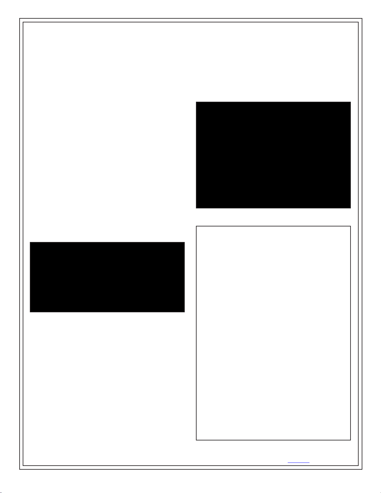
IV. Push and hold the ALARM RESET button on the
ionizer until the STATUS LED turns red (see Figure 7).
Release thebutton and the LED should switch back to
green. Thisallows the user to calibrate the balance
(offset voltage) of the ionizer without setting off the
alarm.
V. The balance (offset voltage) of each fan should be
within 0 and ±15 volts. The required limit per
ANSI/ESD S20.20 is less than ± 50 volts. To increase
the output in a positive direction, turn the BALANCE
ADJUST potentiometer in a clockwise direction. To
increase the output in a negative direction, turn the
BALANCE ADJUST potentiometer in a counter-
clockwise direction.
VI. Test the neutralization (discharge) time by applying a
±1,000 volt on the charged plate. The neutralization
(discharge) time should be less than 3 seconds when
charged plate analyzer is directly under a fan. See
figures 5 and 6 for typical discharge times. The
required limit per ANSI/ESD S20.20 is “user defined”.
Figure 7. Calibration controls
VII. Submit the balance (offset voltage) to the ionizer’s
control circuit by quickly pressing the ALARM RESET
button. The STATUS LED should turn off and then
illuminate green to verify that the control circuit was
successfully programmed.
VIII. Test each fan’s alarm by shorting its two grills located
on the bottom side of the ionizer (see Figure 8). The
alarm should sound and the STATUS LED should
illuminate red.
Figure 8. Shorting the ionizer’s two fan grills