Page 7
Replacing the cell in cabinet
After the cell has been washed, check for broken ionizer
wiresandbentcollector plates.If brokenwires areobserved,
return unit to Authorized Warranty Station for wire
replacement.If bent collector platesare observed, carefully
straighten with a screwdriver or other flat object. BE
CERTAIN THAT NO TWO COLLECTOR PLATES ARE
TOUCHING AS THIS WILL CAUSE ARCING AND
PREVENT THE AIR CLEANER FROM OPERATING
PROPERLY.
Rememberthattheelectronicaircleanerhasacellkeywhich
prevents the cell from being positioned incorrectly. If the
cell seems stuck when being inserted or the access cover
will not fit securely, check to be sure that the cell is being
positioned properly.If excessive force isused, thecell orair
cleanerunit could be damaged.Airflow arrowspoint toward
fan motor.
If the cell is placed into the air cleaner while still damp, the
indicator light may not come on until the cell is dry, which
wouldnormallytakeabout twohours.Ifthe cellis energized
and annoying snapping sounds occur, the cell should be
removedfrom theair cleanerand allowedtothoroughly dry.
Activated carbon filter
The activated carbon filter should be replaced when it is no
longer effective in eliminating odors.The life of the carbon
filterwill dependon theconcentration ofodors and fumes in
the air passing through the air cleaner. Under normal
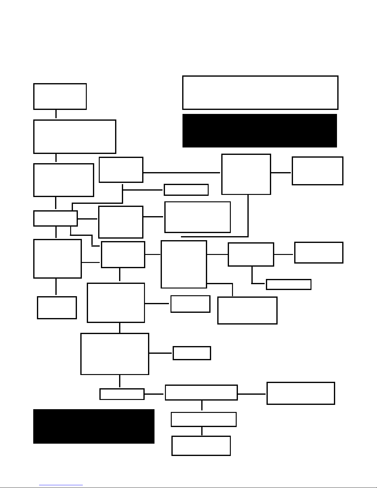
Consumer troubleshooting guide
Intheeventthatyouexperience problemswith the operation
of your air cleaner, please...
•Make sure electronic cell is clean, dry and properly
installed.
•Make sure pre-filter and carbon filter are both properly
installed.
•Make sure the top cover is properly snapped in place.
•Checkfanmotor andindicatorlampon all speedsettings
starting with low.
If your air cleaner still has any of the following problems,
proceedstep bystep as shown below untilno furtheraction
should be taken.
circumstances,the carbon filtershouldlast uptosix months.
THECARBON FILTER MUST BE IN PLACEFORTHEAIR
CLEANER TO OPERATE.
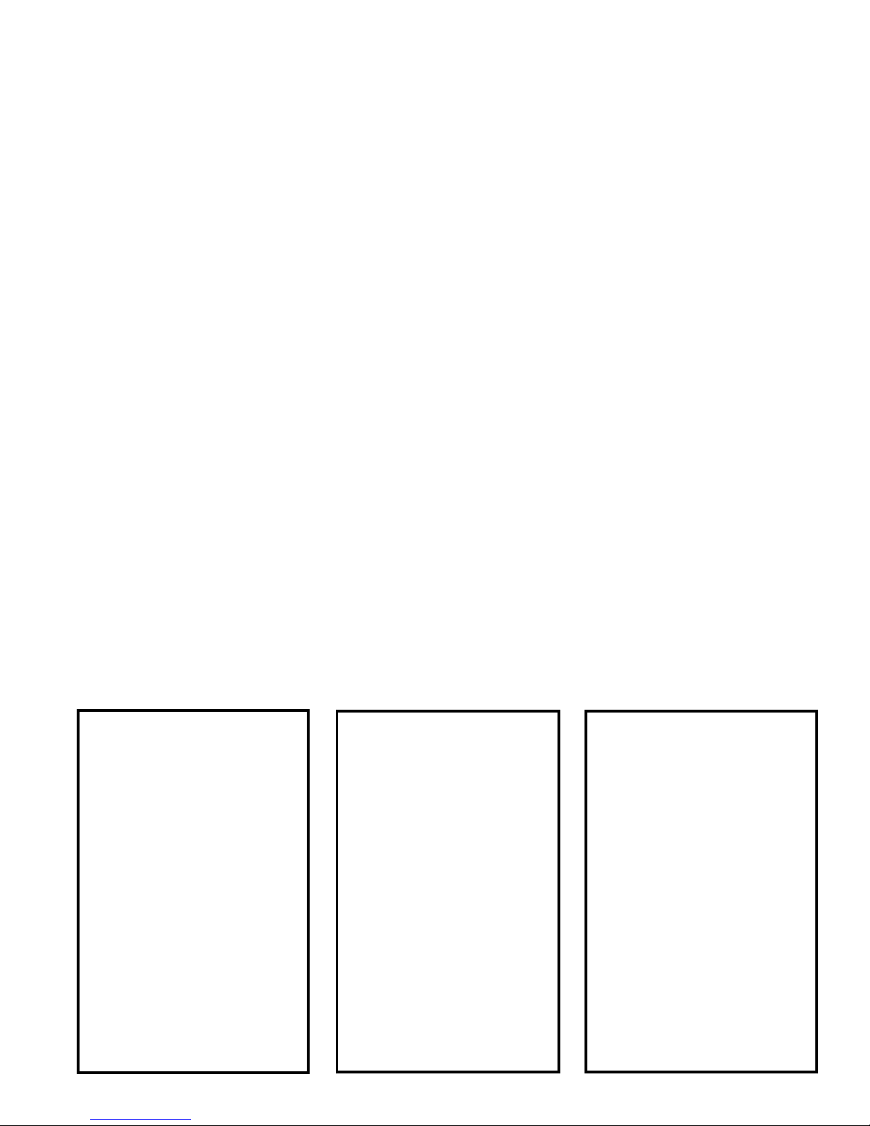
PROBLEM 3
FAN OFF
LAMP ON
This condition represents a non-
serviceable failure of the air cleaner.
Return the unit to an Authorized
Warranty Station for repair. See Page
12.
PROBLEM 2
FAN ON
LAMP OFF
Check the electronic cell to see if any
of the collector plates are touching.
Gently straighten and evenly space
the plates.
Check the electronic cell to see if any
of the ionizer wires are broken. See
Major Components for their location.
If broken wires are observed, no
further corrective actions should be
taken by the consumer. Return the
unit to an Authorized Warranty
Station for repair. See Page 12.
PROBLEM 1
FAN OFF
LAMP OFF
Make sure the supply cord is plugged
into a standard household receptacle.
Make sure there is voltage to the
receptacle by testing with another
electric device.
Make sure the carbon filter is in place.
Make sure the top access cover is
properly in place in order to actuate the
interlock switch. The interlock switch
is provided for consumer safety and
should never be bypassed.
No further corrective actions should be
taken by the consumer. Return the unit
to an Authorized Warranty Station for
repair. See Page 12.