Desert Aire ExpertAire LC Series User manual
Installation and Operation Manual
• Meets AHRI Standard 910.
• Effective humidity control:
4 to 100 lbs per hour.
• Wide range of ambient
temperatures: 65° to
95° F.
• Air conditioning option.
• Optional outdoor air
intake to help meet
ASHRAE 62 ventilation
requirements.
• Multiple heat sink options
including pool water
heating.
• Scroll compressors for
high efficiency and
longevity.
• Galvanneal cabinet with
high impact, powder coat
textured paint.
• Auxiliary heat including
hot water and electric
coils.
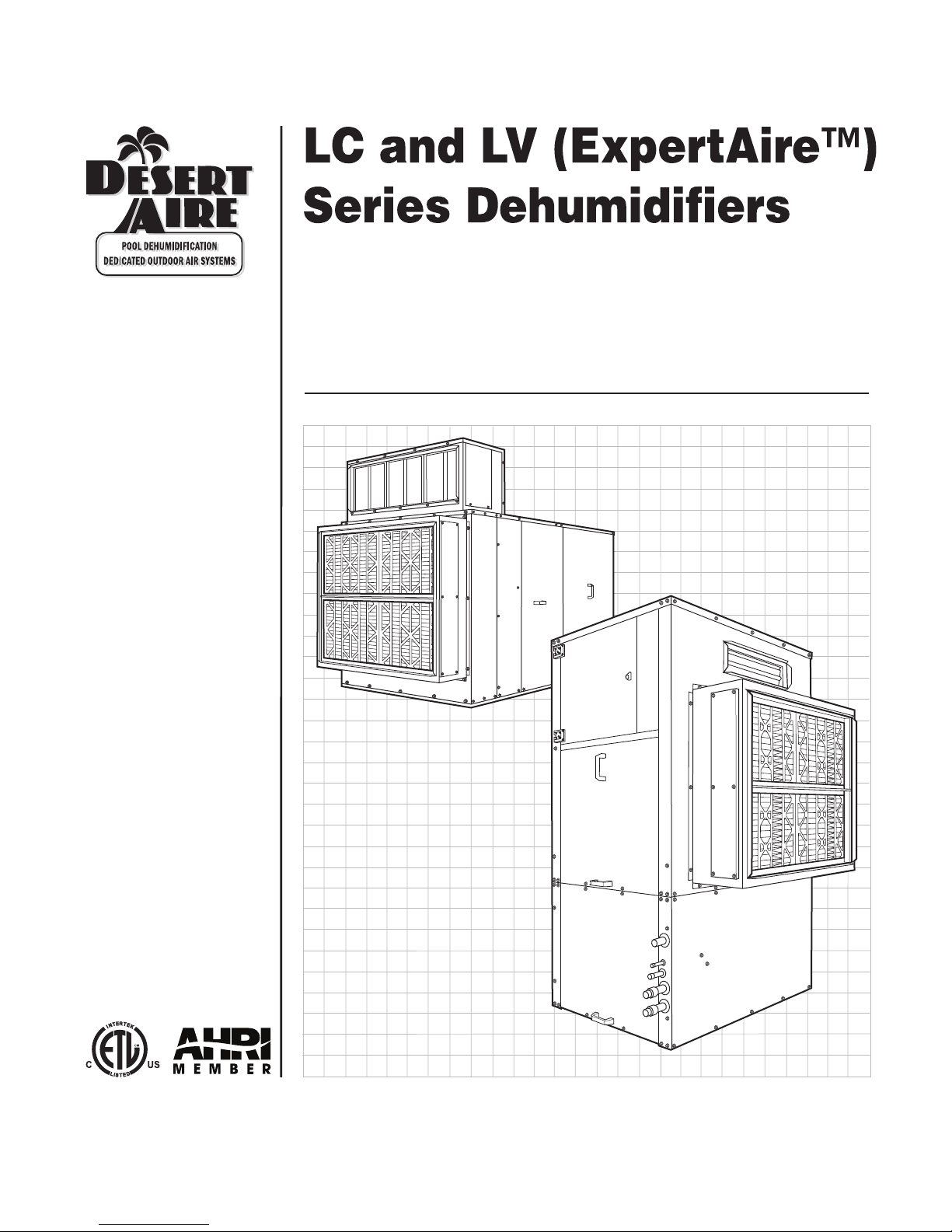
LC System
LV System

2

3
Desert Aire - LC/LV Manual
DANGER
ONLY TRAINED, QUALIFIED PERSONNEL SHOULD INSTALL AND/OR SERVICE
DESERT AIRE EQUIPMENT. SERIOUS INJURY, DEATH AND PROPERTY DAMAGE CAN
RESULT FROM IMPROPER INSTALLATION/SERVICE OF THIS EQUIPMENT. HIGH VOLTAGE
ELECTRICAL COMPONENTS AND REFRIGERANT UNDER PRESSURE ARE PRESENT.
Desert Aire
Dehumidication Equipment Standard Limited Warranty
Desert Aire warrants the dehumidifying unit to be free from defects in materials and workmanship subject to the terms,
conditions and limitations stated herein.
TERMS
Desert Aire warrants all components (except as noted) for a period of two (2) years from the date of shipment. This
warranty shall be limited to the supply of new or rebuilt parts for the part which has failed because of
defects in workmanship or material, and does not include the cost for labor, transportation or other costs not herein
provided for. Replaced parts are warranted only for the remaining portion of the original warranty period.
CONDITIONS
The warranty is subject to the following conditions:
1. The unit must be properly installed and maintained in accordance with the Desert Aire
“Installation and Operation Manual” provided with each unit and/or other documentation provided.
2. The Start-Up Report must be completed and returned to Desert Aire Service for evaluation. If no
deciencies are identied a Warranty Validation Letter will be issued that provides all warranty dates
and coverage. If installation or start-up deciencies are present, these must be corrected and
communicated to Desert Aire in order to activate warranty.
3. This warranty shall not apply to any part that has been tampered with, or has been subject to
misuse, negligence or accident. A warranty can be obtained for altered equipment but only with
written consent from Desert Aire.
4. Thefollowingpartsandcomponentsareexcludedfromthewarranty:belts,lters,driers,fusesand
refrigerant.
5. Refrigerant coils or other components that corrode due to improperly balanced pool chemistry or
corrosive air quality will not be warranted.
6. All replacements or repairs will be FOB Germantown, WI.
7. This warranty shall be null and void if defects or damages result from unauthorized opening of the
refrigerant circuit, tampering with factory set controls, or operating outside the original design
conditions.
8. Desert Aire shall not be liable for labor costs incurred in diagnosing the problem, or the removal
or replacement of the part or parts being repaired.
9. Desert Aire must preauthorize all warranty coverage described herein.

4Desert Aire - LC/LV Manual
Extended Warranty:
Your Desert Aire unit may have extended warrantees beyond this Standard Limited Warranty document.
Extended warrantees are only available at the time of the purchase of the original equipment. These extended
warrantees are covered under a separate document and their terms and conditions are separate from this document.
Itismentionedinthisdocumentforinformationalpurposesonly.AnyExtendedWarrantieswillbeidentiedonthe
Warranty Validation Letter.
Any and all incidental or consequential damages are expressly excluded from this warranty. Some states do not allow
the exclusion of incidental or consequential damages for personal injury, so the above limitations may not apply to you
for certain damages. This warranty gives you specic legal rights, and you may also have other rights, which vary
from state to state. No person or representative is authorized to make any warranty or assume any liability not strictly
in accordance with the aforementioned.
Inquiries regarding warranty matters should be addressed to:
Desert Aire Corp
c/o Service Manager
N120 W18485 Freistadt Road
Germantown, WI 53022
PH: (262) 946-7400
FAX: (262) 946-7401
Additional copies of this manual can be purchased for a nominal fee from Desert Aire. Submit requests to the contact
information listed above.

5
Desert Aire - LC/LV Manual

6
Safety Labels are used throughout this manual. They comply with the ANSI Z535.4 Standard.
Please be familiar with the following labels and their denitions.
This is the safety alert symbol. It is used to alert you to potential
personal injury hazards. Obey all safety messages that follow this
symbol to avoid possible death or injury.
Indicates an imminently hazardous situation which, if not
avoided, will result in death or serious injury.
Indicates a potentially hazardous situation which, if not
avoided, could result in death or serious injury.
Indicates a potentially hazardous situation which, if not
avoided, could result in minor or moderate injury.
Caution used without the safety alert symbol indicates a
potentially hazardous situation which, if not avoided, could
result in property damage.
Desert Aire - LC/LV Manual

7
TABLE OF CONTENTS
1. Introduction ...................................................................................................................... 9
1.1. Inspection ............................................................................................................... 9
1.2. Freight Damage Claims ........................................................................................... 9
1.3. Rigging
....................................................................................................................
9
1.3.1.RiggingtheDehumidier
............................................................................
9
1.3.2. Rigging the Remote Condenser ................................................................. 10
2. Installation ........................................................................................................................ 11
2.1. LocationofDehumidier......................................................................................... 11
2.2. Duct Installation ....................................................................................................... 13
2.3. Condensate Drain Piping ........................................................................................ 16
2.4. Water Heating Applications ..................................................................................... 18
2.4.1. Water Piping Connections ......................................................................... 18
2.4.2. Low Water Flow Protection ........................................................................ 21
2.5. Remote Condenser (Optional) ................................................................................ 21
2.6. High Voltage Wiring ................................................................................................ 24
2.6.1. High Voltage Connections
.....................................
...........
.........................
24
2.6.2. Wire and Fuse Sizing ...............................................
..............................
.... 25
2.7. Controls and Sensors ............................................................................................. 25
2.7.1. Wall Mount Sensor .....................................................
...........
..................... 25
2.7.2. Duct Mount Sensor .................................................................................... 25
2.8. Auxiliary Heating Control Wiring ............................................................................. 25
2.8.1. Auxiliary Heating - Dry Contact Closure .................................................... 25
2.8.2. Auxiliary Heating - Proportional Signal .............................
................
......... 26
2.9. Smoke Alarm Interlock ............................................................................................ 26
3. Start-up Procedure ........................................................................................................ 27
3.1. Preliminary Inspection ..........................................................................
...............
... 27
3.2. Outdoor Air Applications ...................................................................
.................
..... 28
3.2.1. Outdoor Air Option Equipped Units ..................................
...................
....... 28
3.2.2. Standard Systems in Conjunction with Outdoor Air ................................... 30
3.2.3. Outdoor Air Supplemental Information ....................................................... 31
3.2.3.1 LC and LV Operation Modes .................................
.............
.......... 31
3.2.4. Determining if Outdoor Air Pre-Heating is Required .................................. 31
3.2.5. Approximating Outdoor Air Volume ............................................................ 32
3.3. AirowBalancing..................................................
.................
................................. 33
3.3.1. Blower Adjustment Procedure ..................................................
............
...... 33
3.3.2. AirowBalancingforLCDehumidiers...........................
.............
............. 34
3.3.3. AirowBalancingforLVDehumidiers...................................................... 36
3.4. Refrigeration Testing ............................................................................................... 38
3.5. General Testing ........................................................................
......................
........ 40
Desert Aire - LC/LV Manual

8Desert Aire - LC/LV Manual
3.6. Routine Maintenance Schedule ............................................................................. 40
3.6.1. Service Every Month ................................................................................. 40
3.6.2. Service Every Six Months ......................................................................... 41
3.6.3. Pool Water Chemistry ............................................................................... 41
4. Troubleshooting ............................................................................................................. 43
4.1. The Blower Does Not Run ..................................................................................... 43
4.2. The Compressor Does Not Run ......................................................
.................
...... 43
4.3. Evaporator Coil Ices Up ......................................................................................... 44
4.4. Head Pressure is Too High ..........................................................
...................
........ 45
4.5. Unit Runs but Excess Condensation on Walls and Windows ........
....................
.... 46
4.6. Pool Water Heating Problems (Water-Cooled Units Only) ...................................... 46
5. Appendix .......................................................................................................................... 47
5.1. Compressor Failure ............................................................................................... 47
5.1.1. Compressor Replacement .............................................
.....................
...... 47
5.2. Recommended Duct Design .......................................................
..................
........ 51
5.3. System Guidelines ...........................................................................
............
......... 52
5.3.1. Recommended Controller Settings ..............................
..............
.............. 52
5.3.2. Refrigeration System Pressures ........................
..................
..................... 52
5.3.3. Temperature Rise or Drop Across Unit ..................................................... 52
5.4. Sequence of Operation ...........................................................
...................
........... 53
5.4.1. DehumidicationandAirReheat.............................................................. 53
5.4.2. DehumidicationandAirCooling.........................
.......................
............. 53
5.4.3. Cooling and Water Heating (Water-Cooled Unit Only) ............................. 53
5.4.4. DehumidicationandWaterHeating(Water-CooledUnitOnly)...
.......
...... 53
5.4.5. Partial Pool or Spa Water Heating ..................................
............
.............. 54
5.4.6. Operation of Water Condensers and Optional Pump Starts ....
...............
... 54
5.4.7. Blower Operation ............................................................
...................
........ 54
5.4.8. Air Heat (Optional) ..............................................................
............
.......... 54
5.4.9. Outdoor Air (Outdoor Air Equipped Models Only) ..................
..............
..... 55
5.5. Component Replacement, Charge, Evacuation, & Leak Instructions ..
........
.......... 55
5.6. Rating Plate ........................................................................................................... 60
5.7 Start-up Supervision Supplemental Information (Optional) ................................... 60
5.8. System Start-up Report ......................................................................................... 61
LC/LV Factory Start-up Supervision ....................................................................... 62
LC/LV Start-up Report ............................................................................................ 64
LC/LV Series Compressor Replacement Form ...................................................... 68

9
Desert Aire - LC/LV Manual
1. Introduction
DesertAiredehumidiersaredesignedtoprovideyearsofreliableservicewheninstalled
properly.Readtheseinstructionscarefullybeforeyouinstallthedehumidier.
1.1 Inspection
DesertAireinspectsandtestseachdehumidierbeforeitleavesthefactorysothat
you receive a quality piece of equipment. Unfortunately, equipment may become
damagedintransit.Inspectthedehumidiercarefullybeforesigningthereceiving
papers. Check for both visible and concealed damage. Remove crating and inspect
theexteriorcabinetfordamage.Dentedpanels,brokencratingoranyuidsleaking
from the unit should be documented upon delivery.
1.2 Freight Damage Claims
Ifthedehumidierhasbeendamaged,documenttheextentofthedamage.Take
pictures.Next,obtainaclaimformfromthecarrier.Promptlylloutandreturnthe
form.Carriersmaydenyclaimsthatyouhavenotlledoutwithinaweekofdelivery.
Notify Desert Aire of any damage.
1.3 Rigging
1. Failure to observe rigging instructions may lead to equipment damage, personal
injury, or death.
2. Lifting method and procedure must comply with all local and national codes and
regulations.
3. The use of safety slings in addition to lifting lugs is required.
4. Do not lift the dehumidifier in high winds or above people.
DesertAiredehumidiersaresolidlybuiltandcanbeveryheavy.Avoidpersonal
injury and damaging the equipment by planning the installation carefully. Use moving
equipment whenever possible.
1.3.1 Rigging the Dehumidier
Depending upon the unit type, various rigging methods are used to best lift the
equipment. Personnel should avoid stepping on the top of the unit. Desert
Airedehumidiersarenotdesignedtosupporttheweightofapersononall
portions of the roof. Damage incurred through caved or distorted top panels
will not be covered under warranty.
10
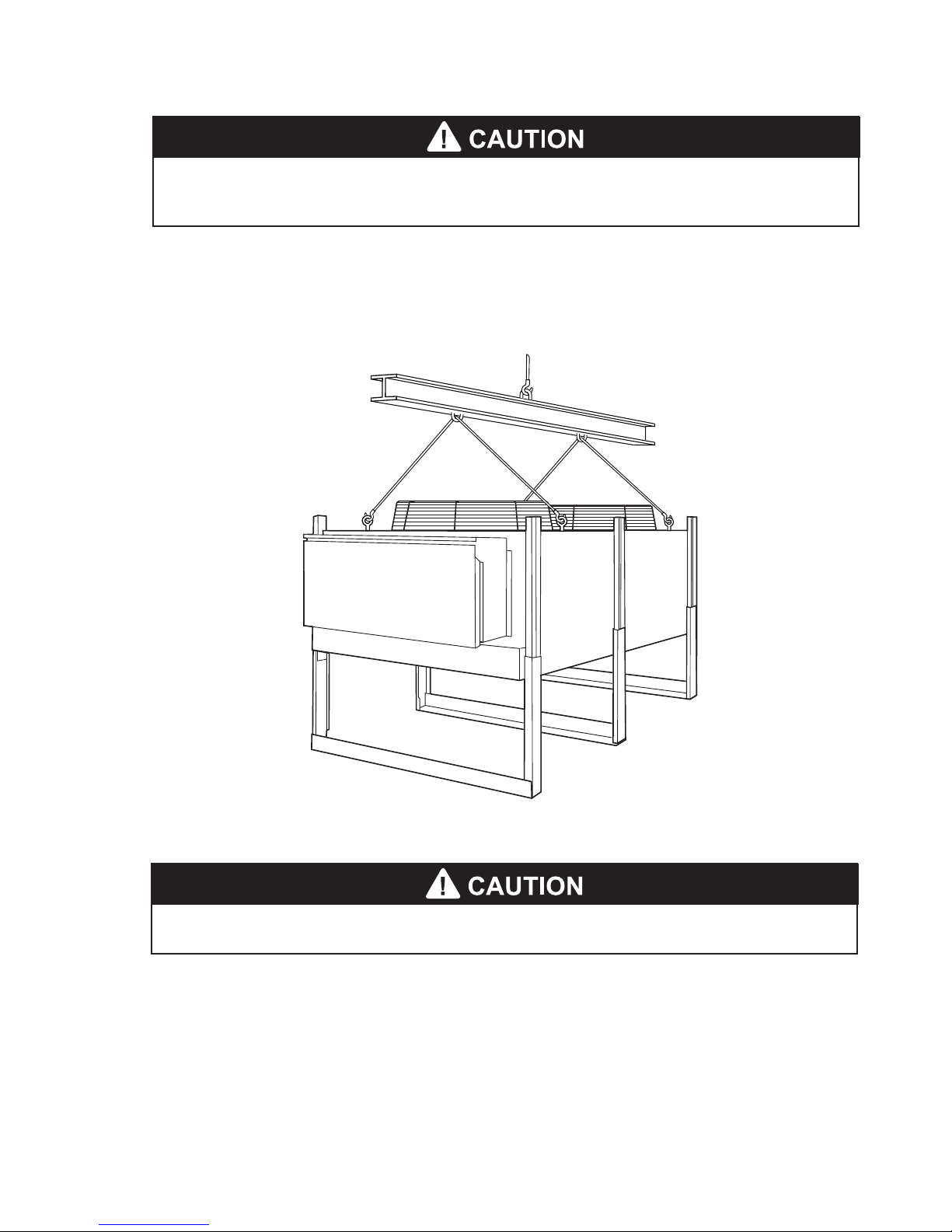
1.3.2 Rigging the Remote Condenser
The optional remote condensers are equipped with four or more lifting eyes.
Test-lift the remote condenser to verify that it is properly balanced.
Figure 1 - Typical Rigging for an Optional Remote Condenser
1. Do not lift the remote condenser by its refrigeration headers or return bends.
1. Do not tip the dehumidifier on its side.
2. Avoid dropping the unit down stairways or subjecting it to severe mechanical shock.
Desert Aire - LC/LV Manual
11
Desert Aire - LC/LV Manual
2 Installation
Manual applies to standard unit congurations only.
2.1 Location of Dehumidier
DesertAireLCdehumidiersrequirebothleftandrightsideserviceaccesstotheunitfor
service.TheLVdehumidiersrequireserviceaccesstotheleftsideendoppositethereturn
air connection. Allow a minimum of 36 inches of clearance around the service sides of the
dehumidierforpiping,electricalconnections,andserviceaccess.Thenon-accesssidesof
the unit should have a minimum of 12 inches of clearance. Consult local, state, and national
electric codes for other minimum service clearances.
Install the unit on a sturdy, level mounting base or platform that will prevent vibration and
soundtransmission.Neverinstallthedehumidieronawoodenplatformwithoutconsulting
the design engineer for spring isolation requirements and sound control materials. Do not
installtheunitnearoccupiedroomssuchasofcesorguestrooms.Donotattemptto
conserve installation space by fabricating restrictive ductwork with abrupt bends. You may
reducetheoperatingefciencyandthemoistureremovalcapacityofthedehumidier.See
section 5.2 for detailed duct installation instructions.
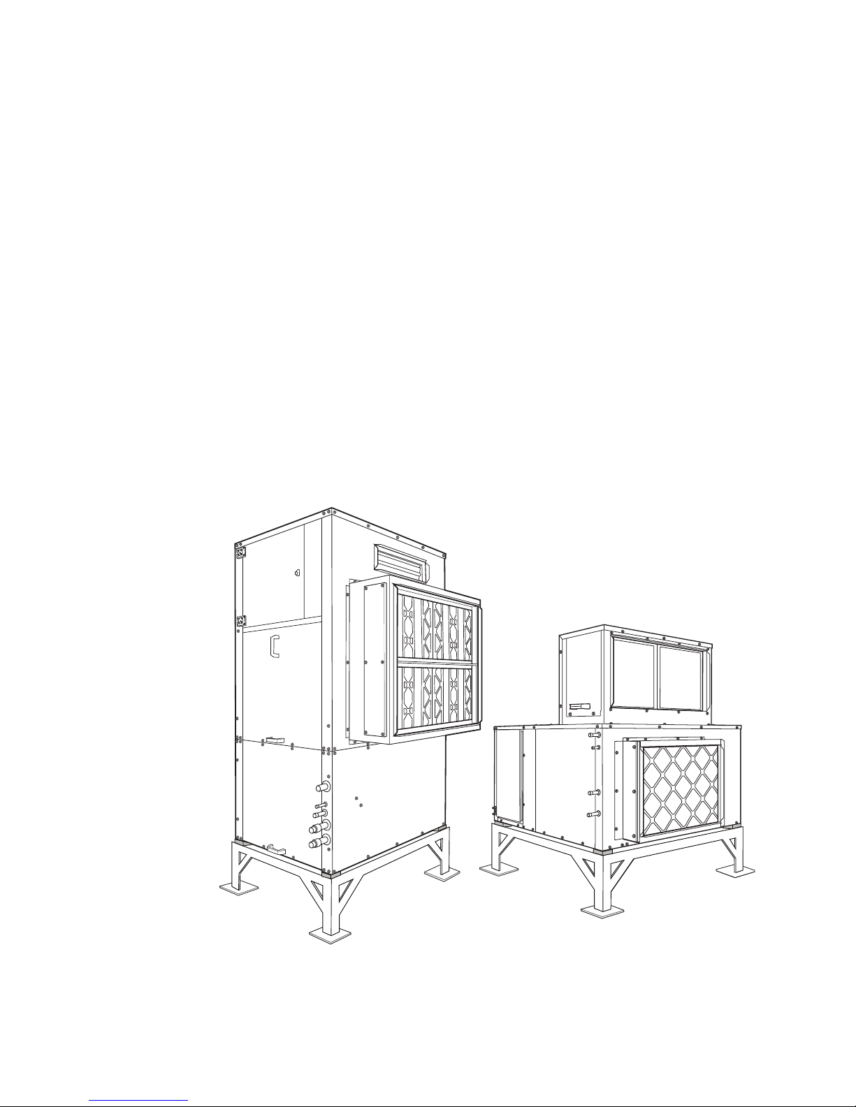
Figure 2 - Typical Floor Installation

12
Figure 3 - Typical Suspended Installation - LC Only (LV Units are oor units only)
LV Only - Do not install an indoor-rated dehumidier in an outdoor or a wet
environment.
You must not install a standard dehumidier in an unconditioned space or where ambient
temperatures can fall below 45°F.Ifyoumustinstallthedehumidieroutsideorinan
unconditionedspace,suchasanattic,youmustuseanoutdoor-rateddehumidier.Desert
Aireequipsoutdoor-rateddehumidierswithweatherproongandthickerinsulation.Youcan
determinewhetheryourdehumidierisoutdoorratedbyinspectingtheunitratingplate.See
section 5.6 for details.
Desert Aire - LC/LV Manual
13
Desert Aire - LC/LV Manual
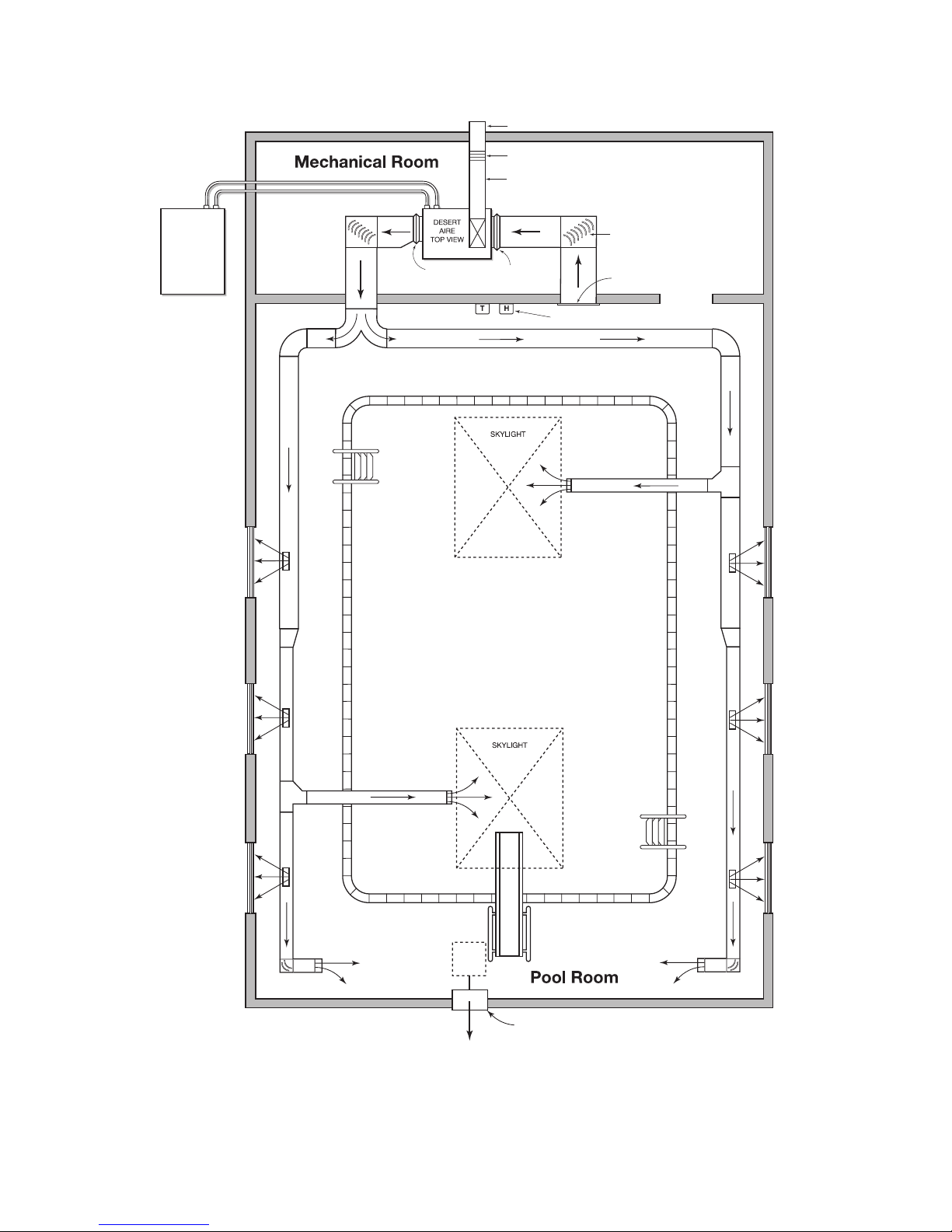
2.2 Duct Installation
Duct design and installation should conform to the latest ASHRAE and SMACNA low velocity
duct standards. See section 5.2 for details. Undersized restrictive ductwork with abrupt turns
ortransitionscandecreasetheefciencyandthemoistureremovalcapacityofyour
dehumidierandmayleadtounitfailure.Sizetheductworkforanacceptableairpressuredrop
attheairowvolumeofyourdehumidier.Useneopreneexconnectorswhenyouattach
ductworktothedehumidiertopreventtransmissionofexcessvibrationandnoise.
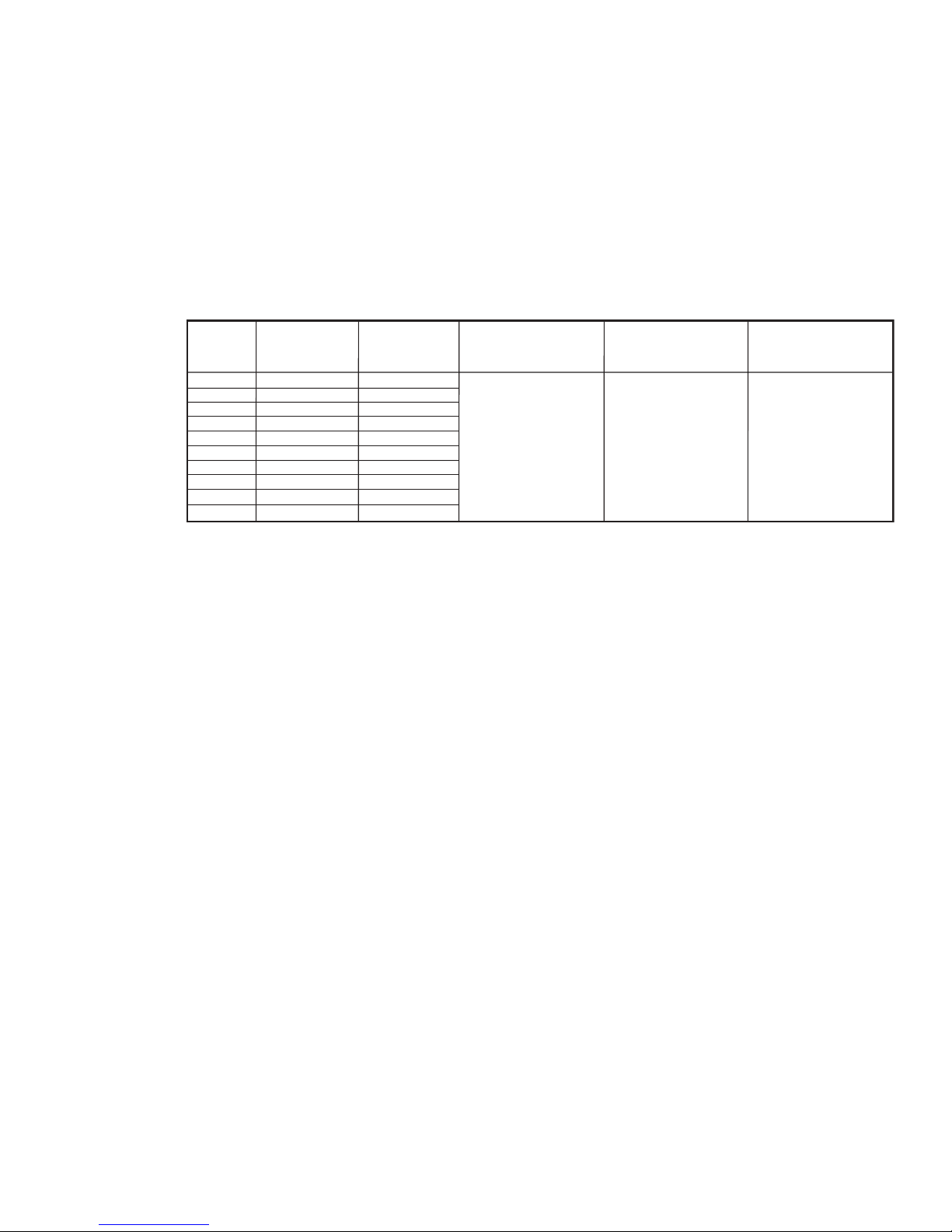
Airflow Rate (CFM)
(LV Only)
-
-
1400
2100
3000
3400
3800
-
-
-
External Static Pressure
(ESP) digit 9 for LC (A, B, C,
K, L, M); digit 10 for LV (A, D)
0.5” WC
Airflow Rate (CFM)
(LC Only)
540
950
1400
1900
2300
3000
3500
4100
5500
8000
Model Size
01 (LC Only)
02 (LC Only)
03
04
05
06
08
10 (LC Only)
12 (LC Only)
15 (LC Only)
External Static Pressure
(ESP) digit 9 for LC (D, E, F,
N, P, R); digit 10 for LV (B, F)
1.0” WC
External Static Pressure
(ESP) digit 9 for LC (G, H, J,
S, T, U); digit 10 for LV (C, G)
1.5” WC
Figure 4 - LC and LV Series Standard Unit Airow Specications
Select the grilles, registers and diffusers for low static pressure loss, required throw distance,
andthespeciedCFMrating.Youcanndthisinformationinmostgrillemanufacturer’s
catalogs. If you are installing the grilles in a corrosive environment, choose components made
from anodized aluminum.
Ifyoumustinstallductworkinanunconditionedarea,useberglassductwrapwithvapor
barrier facing. You must install the outdoor air intake away from all sources of airborne
contamination such as exhaust fans or plumbing vents. You can use galvanized sheet metal
ducts for most applications. However, you should use aluminum or stainless steel ducts for
extreme applications such as chemical-laden environments.
14
FLEXIBLE NEOPRENE
DUCT CONNECTOR
LOCATE ANODIZED ALUMINUM
RETURN AIR GRILLE AS HIGH
AS POSSIBLE IN ROOM.
INSTALL TURNING VANES
IN ALL ELBOWS.
INSULATED OUTSIDE AIR INTAKE DUCT,
(SIZE FOR CODE REQUIREMENTS)
MOTOR OPERATED DAMPER
WEATHER-PROOF INTAKE HOOD
REMOTE
CONDENSER
TEMPERATURE AND HUMIDITY CONTROLS
MECHANICAL EXHAUST WITH BACK-DRAFT DAMPER
(WALL OR ROOF MOUNTED)
NOTE: EXHAUST LOW
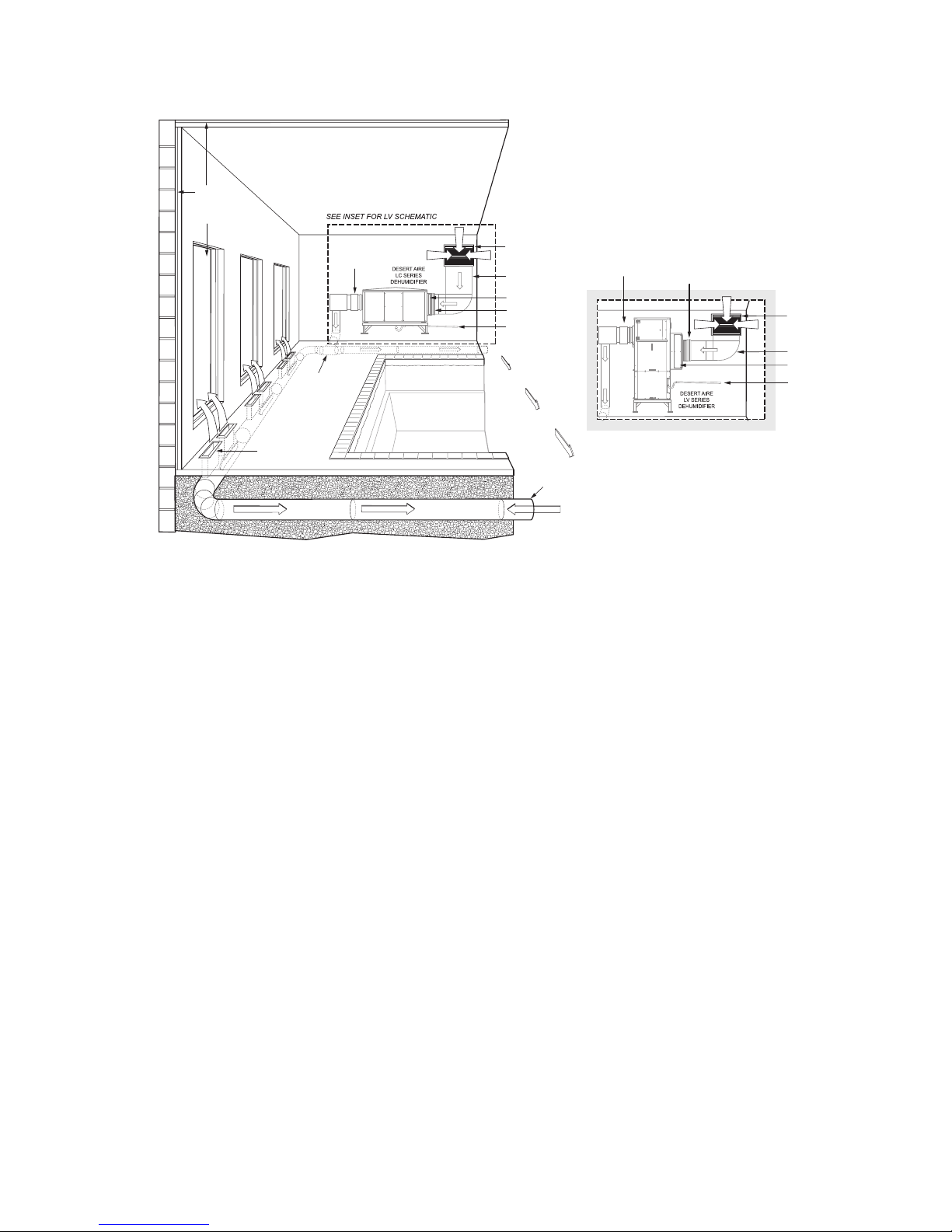
Figure 5 - Basic Pool Room Layout
Desert Aire - LC/LV Manual

15
Desert Aire - LC/LV Manual
VAPOR BARRIER
MAIN SUPPLY
AIR DUCT
WINDOW
POOL
BRANCH SUPPLY AIR DUCT
ANODIZED ALUMINUM
RETURN AIR GRILLE
LOCATE AS HIGH AS POSSIBLE
RETURN AIR DUCT
DESERT AIRE DEHUMIDIFIER
SKYLIGHT
FLEXIBLE DUCT
CONNECTIONS
POOL DECK
ANODIZED ALUMINUM
CEILING DIFFUSER
ANODIZED ALUMINUM
SIDEWALL REGISTER
VAPOR BARRIER
ANODIZED ALUMINUM
RETURN AIR GRILLE
LOCATE AS HIGH AS POSSIBLE
RETURN AIR DUCT
FLEXIBLE DUCT
CONNECTIONS
Figure 6 - Soft Duct Layout
16
VAPOR BARRIER
AUX. HEATING
WINDOW
ANODIZED ALUMINUM
FLOOR DIFFUSERS
(SIZE FOR PROPER
AIR FLOW)
SUPPLY PIPING
LOOP SYSTEM
POOL
P. C.D. COATED SPIRAL
GALVANIZED PIPE
ANODIZED ALUMINUM
RETURN AIR GRILLE
LOCATE AS HIGH AS
POSSIBLE
RETURN AIR DUCT
FILTER RACK
FLEXIBLE DUCT
CONNECTIONS
POOL DECK
CONDENSATE PIPING
AUX. HEATING
ANODIZED ALUMINUM
RETURN AIR GRILLE
LOCATE AS HIGH AS
POSSIBLE
RETURN AIR DUCT
FILTER RACK
FLEXIBLE DUCT
CONNECTIONS
CONDENSATE PIPING
Figure 7 - Under-Floor Duct Layout
2.3 Condensate Drain Piping
Thecondensatedrainconnectionmaybeonthesideorthebottomofthedehumidier,
depending on the size and style of cabinet used. Use concrete blocks or steel dunnage to
raisethedehumidierhighenoughabovetheoortoprovideclearancefortheeld-supplied
condensate drain trap.
Note:Whilethesupplyblowerruns,thedrainpanareainsidethedehumidieroperatesata
negative pressure. Your unit requires a p-trap in the condensate drain pipe to prevent
condensatefrombeingdrawnintothecabinetofthedehumidier.
Desert Aire - LC/LV Manual

17
Desert Aire - LC/LV Manual
Min. 12”
P-Trap (By Others)
Vibration
Isolator
Base /Support
(By Others)
1/4” Slope
Per Foot
Min. 12” Vibration
Isolator
Base /Support
(By Others)
P-Trap
(By Others) 1/4” Slope
Per Foot
Figure 8 - Condensate Piping
4”
4”
Figure 9 - Sectional View of Condensate Trap Requirements
Trap the condensate as shown in Figure 9. The P-trap dimensions in Figure 9 are sized for a
maximumreturnairstaticof2.0”ofwater.Ifyourreturnairstaticexceedsthisspecication,
consult Desert Aire for help in resizing the P-trap.
You may also need to install a cleanout tee or plug near the trap. Note that the drain
opening in the drain pan is off-center to simplify its cleaning and servicing. Once you have
designed and installed the trap, follow this sequence:

18
1. Connect the trap to a main drain line with 1/4” of downward pitch
per linear foot of run.
2. Supportthedrainpipeeveryvefeettopreventsagging.
3. After you install the drain piping, prime the trap by pouring water
intothedrainpanofthedehumidier.
Condensate drain lines installed in an unconditioned space must be heat taped to
prevent freezing. Check the heat tape yearly before winter operation.
2.4 Water Heating Applications
2.4.1 Water Piping Connections
DesertAireLCandLVSeriesdehumidiersequippedwithpoolwaterheating
condensersmustbeconnectedtopoolwaterltrationlinestooperateasintended.
Thedehumidierwatersupplycircuitmusttapintothemainpoolwaterline
downstreamfromthemainlter.Ifthemainpoolcirculatingpumpislargeenough,
you can use a manual throttling valve to divert a portion of the water to the
dehumidier.Normally,youmustsizeandinstallanauxiliarywaterpumpwhichcan
handletheunit’srequiredwaterowrate,whichislistedinFigure10.Ifyouareusing
a water source other than a pool or a spa (such as a chilled water loop), the required
owratehasbeenprintedonalabelafxednearthewaterlinestubsofthedehumidier.
01 (LC Only)
02 (LC Only)
03
04
05
06
08
10 (LC Only)
12 (LC Only)
15 (LC Only)
Water Flow Rate and
Pressure Drop
Pool Application
2 GPM @ 5.5 ft W.C.
4 GPM @ 6.9 ft W.C.
6 GPM @ 5.3 ft W.C.
8 GPM @ 6.1 ft W.C.
10 GPM @ 5.7 ft W.C.
12 GPM @ 9.2 ft W.C.
16 GPM @ 9.0 ft W.C.
20 GPM @ 5.7 ft W.C.
24 GPM @ 7.4 ft W.C.
30 GPM @ 5.7 ft W.C.
Model Size
Water Flow Rate and
Pressure Drop
Spa Application
3 GPM @ 10.6 ft W.C.
5 GPM @ 9.9 ft W.C.
8 GPM @ 8.5 ft W.C.
11 GPM @ 9.1 ft W.C.
13 GPM @ 8.3 ft W.C.
16 GPM @ 14.8 ft W.C.
18 GPM @ 10.8 ft W.C.
26 GPM @ 8.3 ft W.C.
31 GPM @ 9.7 ft W.C.
39 GPM @ 8.3 ft W.C.
Water Flow Rate and
Pressure Drop
Partial Pool/Spa Application
1 GPM @ 1.8 ft W.C.
1 GPM @ 1.8 ft W.C.
2 GPM @ 2.3 ft W.C.
2 GPM @ 2.3 ft W.C.
5 GPM @ 3.9 ft W.C.
5 GPM @ 3.9 ft W.C.
9 GPM @ 4.8 ft W.C.
9 GPM @ 4.8 ft W.C.
10 GPM @ 6.9 ft W.C.
14 GPM @ 7.2 ft W.C.
Figure 10 - Standard Unit Water Flow Rates for LC and LV Units
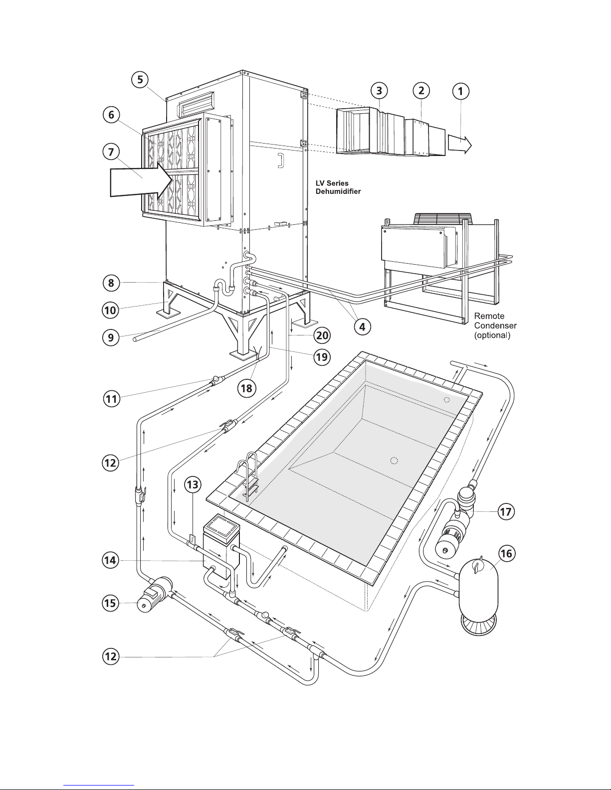
A typical water circuit arrangement is shown in Figure 11. To simplify the
commissioningandservicingofthisjob,youshouldinstallaowmeterandisolation
valvesinthepoolwaterlineswhichfeedthedehumidier.
Desert Aire - LC/LV Manual

19
Desert Aire - LC/LV Manual
1 Supply Air
2 Duct Heater (Gas, Electric, Etc.)
3 Flex Duct Connector
4 Piping to Remote Condenser
5 Desert Aire LC Dehumidifier
6 Filter Rack Assembly with Filters
7 Return Air
8 Vibration Isolators
9 P-Trap
10 Base (If Required)
LEGEND
11 Check Valve
12 Ball Valve
13 Flow Meter
14 Main Pool Heater
15 Auxiliary Pump
16 Filter Assembly
17 Main Pool Pump
18 Water Temp Sensor (Dry Well)
19 Water Inlet
20 Water Outlet
Figure 11 - Proper Pool Water Heating Installation for Desert Aire LC and LV dehumidiers
20
Figure 12 - Proper Pool Water Heating Installation for Desert Aire LV dehumidiers
Desert Aire - LC/LV Manual
This manual suits for next models
1
Table of contents
Other Desert Aire Dehumidifier manuals


