Desert Aire SelectAire Plus SP Series User manual

Installation and Operation Manual
• Select Aire Plus™ (SP)
systems are dual
refrigeration circuit
dehumidifiers with latent
energy enhancement.
• Cabinet has injected foam
double wall panels for high
insulation properties
and strength.
• Refrigeration circuits
consist of scroll
compressors for high
performance and long life.
• Model features passive
latent heat enhancement
device for high moisture
removal capacity.
• SP systems include an
exclusive exhaust air heat
recovery system and
air flow balancing.
• SP’s dual refrigeration
circuit design allows
staging to minimize
energy consumption and
optimize energy recovery.
SP (SelectAire Plus™)
Series Energy
Recovery Natatorium
Dehumidifiers

2

3
Desert Aire - SP Manual
DANGER
ONLY TRAINED, QUALIFIED PERSONNEL SHOULD INSTALL AND/OR SERVICE
DESERT AIRE EQUIPMENT. SERIOUS INJURY, DEATH AND PROPERTY DAMAGE CAN
RESULT FROM IMPROPER INSTALLATION/SERVICE OF THIS EQUIPMENT. HIGH VOLTAGE
ELECTRICAL COMPONENTS AND REFRIGERANT UNDER PRESSURE ARE PRESENT.
Desert Aire
Dehumidication Equipment
Standard Limited Warranty
Desert Aire warrants the dehumidifying unit to be free from defects in materials and workmanship subject to the terms,
conditions and limitations stated herein.
TERMS
Desert Aire warrants all components (except as noted) for a period of two (2) years from the date of shipment. This
warranty shall be limited to the supply of new or rebuilt parts for the part which has failed because of
defects in workmanship or material, and does not include the cost for labor, transportation or other costs not herein
provided for. Replaced parts are warranted only for the remaining portion of the original warranty period.
CONDITIONS
The warranty is subject to the following conditions:
1. The unit must be properly installed and maintained in accordance with the Desert Aire
“Installation and Operation Manual” provided with each unit and/or other documentation provided.
2. The Start-Up Report must be completed and returned to Desert Aire Service for evaluation. If no
decienciesareidentiedaWarrantyValidationLetterwillbeissuedthatprovidesallwarranty
datesandcoverage.Ifinstallationorstart-updecienciesarepresent,thesemustbecorrected
and communicated to Desert Aire in order to activate warranty.
3. This warranty shall not apply to any part that has been tampered with, or has been subject to
misuse, negligence or accident. A warranty can be obtained for altered equipment but only with
written consent from Desert Aire.
4. The following parts and components are excluded from the warranty: belts, lters, driers, fuses and
refrigerant.
5. Refrigerant coils or other components that corrode due to improperly balanced pool chemistry or
corrosive air quality will not be warranted.
6. All replacements or repairs will be FOB Germantown, WI.
7. This warranty shall be null and void if defects or damages result from unauthorized opening of the
refrigerant circuit, tampering with factory set controls, or operating outside the original design
conditions.

4Desert Aire - SP Manual
8. Desert Aire shall not be liable for labor costs incurred in diagnosing the problem, or the removal
or replacement of the part or parts being repaired.
9. Desert Aire must preauthorize all warranty coverage described herein.
ExtendedWarranty:
Your Desert Aire unit may have extended warrantees beyond this Standard Limited Warranty document.
Extended warrantees are only available at the time of the purchase of the original equipment. These extended war-
rantees are covered under a separate document and their terms and conditions are separate from this document.
It is mentioned in this document for informational purposes only. Any Extended Warranties will be identied on the
Warranty Validation Letter.
Any and all incidental or consequential damages are expressly excluded from this warranty. Some states do not allow
the exclusion of incidental or consequential damages for personal injury, so the above limitations may not apply to you
for certain damages. This warranty gives you specic legal rights, and you may also have other rights, which vary
from state to state. No person or representative is authorized to make any warranty or assume any liability not strictly
in accordance with the aforementioned.
Inquiries regarding warranty matters should be addressed to:
Desert Aire Corp c/o Service Manager
N120 W18485 Freistadt Road • Germantown, WI 53022
Additional copies of this manual can be purchased for a nominal fee from Desert Aire. Desert Aire also posts the most
current revision of our I/O Manuals on our website. For a digital copy of the I/O Manual for your unit revision, please
submit request to the contact information listed above.
GasHeatExchangerTen(10)-YearProratedWarrantyTerms(Forunitswithgasheatonly)
Desert Aire offers an extended prorated eight (8)-year warranty for gas heat exchanger. All other heater components
are covered under the initial 2 year warranty.
2 Years Parts Only from date of shipment. Prorated from years 3-9 as follows:
Year 3: Desert Aire warrants 70% of replacement price
Year 4: Desert Aire warrants 60% of replacement price
Year 5: Desert Aire warrants 50% of replacement price
Year 6: Desert Aire warrants 40% of replacement price
Year 7: Desert Aire warrants 30% of replacement price
Year 8: Desert Aire warrants 20% of replacement price
Year 9: Desert Aire warrants 10% of replacement price
5
Desert Aire - SP Manual
ForUnitsw/GasHeat:
ForYourSafetyReadbeforeOperating
Failure to follow safety warnings exactly could result in serious injury, death or
property damage.
Be sure to read and understand the installation, operation and service instructions
in this manual.
Improper installation, adjustment, alteration, service or maintenance can cause
serious injury, death or property damage.
Do not store or use gasoline or other ammable vapors and liquids in the vicinity of this or any
other appliance.
WHATTODOIFYOUSMELLGAS
• Do not try to light any appliance
• Do not touch any electrical switch; do not use any phone in your building
• Leave the building immediately
• Immediately call your gas supplier from a phone remote from the building.
Follow the gas supplier’s instructions.
• If you cannot reach your gas supplier, call the re department.
Installation must be performed by a qualied installer, service agency or gas supplier.
More safety information is included in the gas furnace manual; therefore, it must be kept
with the appliance for future reference.
A. The included gas fueled furnace(s) does not have a pilot. It is equipped with a direct spark ignition
device that automatically lights the burner. DO NOT try to light the burner by hand.
B. BEFORE OPERATING, leak test all gas piping up the heater gas valve. Smell all around the unit area
for gas. DO NOT attempt to place heater in operation until source of gas leak is identied and corrected.
C. Use only hand force to push and turn the gas control knob to the “ON” position. NEVER use tools. If the
knob will not operate by hand, call a qualied service technician to replace the gas valve prior to starting
the unit. Forcing or attempting to repair the gas valve may result in a re or explosion.

6Desert Aire - SP Manual
D. Do not attempt to operate unit, if there is indication that any part has been under water. Any control or
component under water must be immediately replaced by a qualied service technician prior to trying to
start the unit.
OPERATING INSTRUCTIONS
1. STOP! Read the safety information above on this label and Refer to individual furnace Sequence of
Operation to determine manifold pressures at start-up and during operation on the modulating furnace.
2. Set the thermostat to lowest setting.
3. Turn off all electric power to the appliance.
4. This appliance is equipped with an ignition device that automatically lights the burner. DO NOT try to light
the burner by hand.
5. On 2-stage units, turn gas control knob clockwise to “OFF” position or switch down for single stage.
6. Wait ve (5) minutes to clear out any gas. Then smell for gas, including near the oor. If you smell gas,
STOP! Follow “B” in the safety information above on this label. If you don’t smell gas, go to next step.
7. Turn gas control knob counterclockwise to “ON” position on 2-stage units or ip up to “ON” for single stage
units. NOTE:DONOTFORCE.
8. Turn on all electric power to unit.
9. Set thermostat to desired setting.
10. If appliance will not operate, follow the instructions “To Turn Off Gas To Appliance” and call your service
technician or gas supplier.
TOTURNOFFGASTOAPPLIANCE
1. Set thermostat to lowest setting.
2. Turn off all electric power to the appliance if service is to be performed.
3. On 2-stage units, turn gas control knob clockwise to “OFF” position or switch down for single
stage. DONOTFORCE.
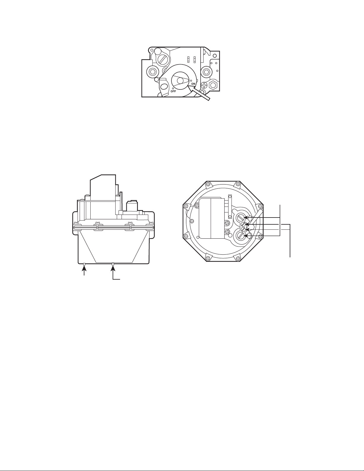
Gas Control
Switch
On / Off (1 Stage) Gas Valve
7
Gas Control
Knob
SIDE VIEW TOP VIEW
INLET
PRESSURE
TAP
OUTLET
PRESSURE
TAP
PRESSURE
REGULATOR
ADJUSTMENT
CAPS
ATMOSPHERIC
PRESSURE
REFERENCE
PORT WITH
INTERNAL
VENT LIMITER
Honeywell V8944 Gas Valve for 500,000 and 600,000 models
Desert Aire - SP Manual
2 Stage Gas Valve
8Desert Aire - SP Manual
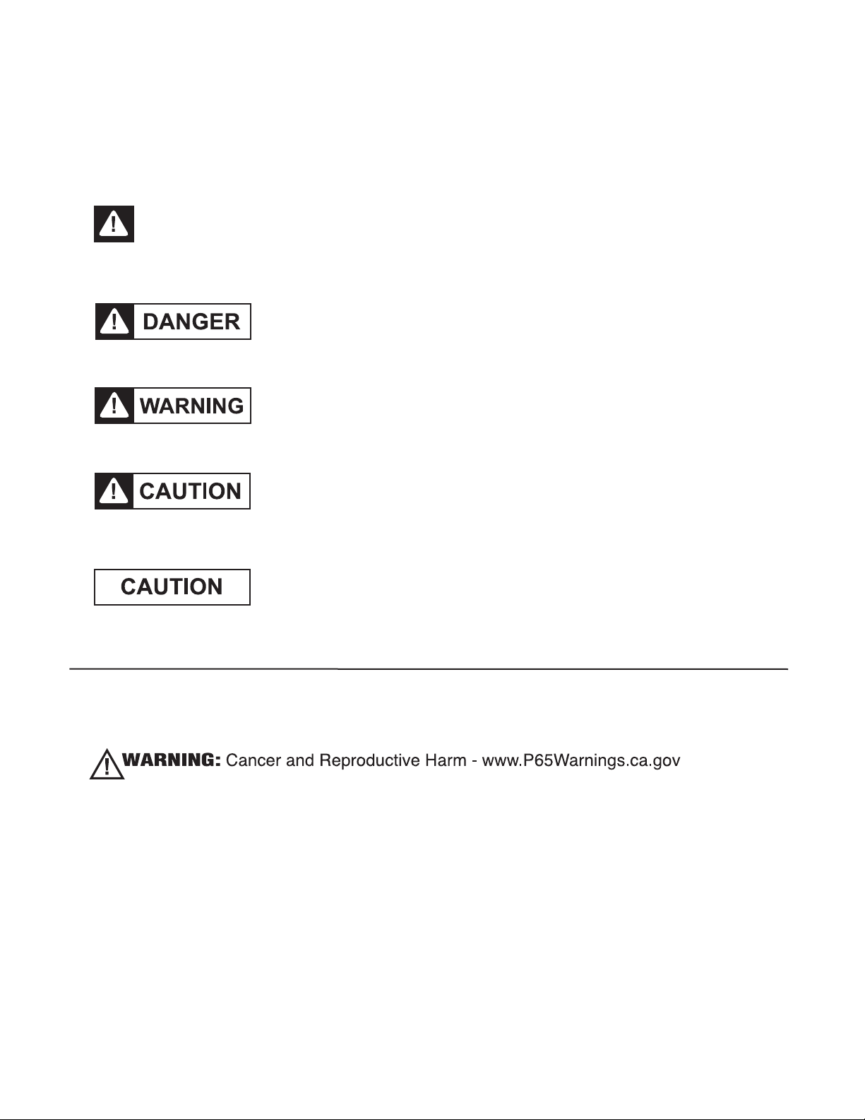
SafetyLabelsareusedthroughoutthismanual.TheycomplywiththeANSIZ535.4Standard.
Pleasebefamiliarwiththefollowinglabelsandtheirdenitions.
This is the safety alert symbol. It is used to alert you to potential
personal injury hazards. Obey all safety messages that follow this
symbol to avoid possible death or injury.
Indicates an imminently hazardous situation which, if not
avoided, will result in death or serious injury.
Indicates a potentially hazardous situation which, if not
avoided, could result in death or serious injury.
Indicates a potentially hazardous situation which, if not
avoided, could result in minor or moderate injury.
Caution used without the safety alert symbol indicates a
potentially hazardous situation which, if not avoided, could
result in property damage.
ProductWarningfortheStateofCalifornia:

9
TABLEOFCONTENTS
1 Introduction ...................................................................................................................... 13
1.1 Inspection ............................................................................................................... 13
1.2 Freight Damage Claims .......................................................................................... 13
1.3 Rigging ................................................................................................................... 13
1.3.1 Rigging the Dehumidier ............................................................................. 13
2 Installation
.......................................................................................................................
15
2.1 Position and Service Clearance ............................................................................. 15
2.2 Outdoor Air and Exhaust Air ................................................................................... 19
2.2.1 Units with Outdoor Air Only ........................................................................ 19
2.3 Condensate Drain Piping ....................................................................................... 21
2.4 Tower and Pool Water Piping .................................................................................. 23
2.4.1 Tower Water Piping ........................................................................................ 23
2.4.2 Pool Water Piping .......................................................................................... 24
2.5 Auxiliary Air Heat Coil Piping ................................................................................. 26
2.6 Remote Condenser (Optional)
..............................................................................
27
2.7 High Voltage Wiring
...............................................................................................
27
2.8 Controls and Sensors
............................................................................................
28
2.8.1 Air Temperature/Humidity Sensors .......................................................... 28
2.8.2 Water Temperature Sensor ........................................................................ 31
2.8.3 Installation of Sensors for the SelectAire Plus™ ....................................... 32
2.8.3.1 Indoor Static Sensor Installation .................................................. 32
2.8.3.2 Outdoor Static Sensor ................................................................... 33
2.8.4 Installation of VOC Monitoring Sensor ....................................................... 34
2.9 Auxiliary Heating Control Wiring
............................................................................
35
2.9.1 Auxiliary Heating - Dry Contact Closure .................................................... 35
2.9.2 Auxiliary Heating - Proportional Signal ...................................................... 35
2.10 Gas Heater (Optional) .............................................................................................. 36
2.10.1 Gas Heater Installation Safety .................................................................. 36
2.10.2 Gas Piping ................................................................................................ 37
2.10.3 Gas Heater Location ................................................................................. 41
2.10.4 Gas Furnace Venting ................................................................................ 44
2.10.4.1 B-Vent Parts .............................................................................. 44
2.10.4.2 Assembly Instructions ................................................................. 44
2.10.5 Indoor Unit Set-up Instructions .................................................................. 45
2.10.6 Finalize Installation .................................................................................... 45
2.10.7 Gas Heater Start-up ................................................................................... 46
2.10.8 Gas Heater Condensate Drain .................................................................. 46
2.10.9 Induced Draft Fan ...................................................................................... 47
Desert Aire - SP Manual

10
2.11 Auxiliary Pool Water Heating .................................................................................. 48
2.12 Smoke Alarm Interlock ............................................................................................ 48
2.13 Auxiliary Air Heater - Hot Water Coils .................................................................... 48
2.14 Packaged Condenser Hail Guard and Pre-Filter Assembly Instructions ................ 49
2.14.1 Packaged Condenser Hail Guard .............................................................. 49
2.14.2 Packaged Condenser Pre-Filters .............................................................. 50
2.14.2.1 Mounting ..................................................................................... 50
2.14.2.2 Inspection ................................................................................... 50
2.14.2.3 Cleaning ..................................................................................... 50
2.15 Section Cabinet Assembly Instructions (Optional) ................................................. 50
2.15.1 Rigging Instructions ................................................................................... 50
2.15.2 Cabinet Assembly ...................................................................................... 50
2.15.3 Refrigeration Piping Reassembly (when applicable) ................................. 52
2.15.4 Refrigeration System Evacuation / Preparation for Operation
(when applicable) ....................................................................................... 52
2.15.5 Electrical Wiring / Airow Tubing Assembly ............................................... 53
2.15.6 Reconnect Differential Pressure Tubing (if applicable) .............................. 53
2.16 Hood Assembly Instructions (if applicable) ............................................................. 54
2.16.1 Outdoor Air Hood Assembly (if applicable) ................................................ 54
2.16.2 Exhaust Hood Assembly Instructions ........................................................ 54
2.17 Combination Moisture and Liquid Indicator ............................................................. 55
2.18 Crankcase Heaters, Heat Tape, GFI Outlets and Lighting ...................................... 56
2.18.1 Crankcase Heaters and Heat Tape ............................................................ 56
2.18.2 GFI Outlets and Lights ............................................................................... 56
2.18.2.1 Dedicated 120V AC Powered Lights, GFI, and Receptacle
(Standard) ................................................................................... 56
2.18.2.2 GFI and Lights Powered by the Dehumidier (Optional) ............ 56
2.18.3 Receptacle for Gas Heat Trap Heat Tape (Outdoor Units Only) ................ 56
3 Start-Up and Maintenance Procedures ................................................................. 57
3.1 Preliminary Inspection ............................................................................................ 57
3.2 Airow Balancing .................................................................................................... 57
3.2.1 Airow Setup of SelectAire Plus™ ............................................................. 58
3.2.2 Final Air Balancing ..................................................................................... 62
3.3 Refrigeration Testing .............................................................................................. 63
3.4 General Testing ..................................................................................................... 65
3.5 Routine Maintenance Schedule ............................................................................. 65
3.5.1 Service Every Month ................................................................................. 65
3.5.2 Service Every Four Months ....................................................................... 65
3.5.2.1 Reheat Condenser Coil Cleaning .................................................. 65
3.5.2.2 ElectroFin Coated Coil Cleaning ................................................... 67
Desert Aire - SP Manual

11
3.5.3 Service Every Six Months ....................................................................... 70
3.5.4 Blower / Fan Maintenance ....................................................................... 71
3.5.5 Auxiliary Heater – Hot Water Coil Maintenance ...................................... 72
3.6 General Service .................................................................................................... 74
3.6.1 Filter Drier Replacement .......................................................................... 74
3.6.1.1 When to Change Cores ............................................................... 74
3.6.1.2 Instructions for Assembly and Charging Cores ........................... 74
4 Troubleshooting .............................................
.....................................................
77
4.1 The Blower Does Not Run .................................................................................... 77
4.2 The Compressor(s) Do Not Run ........................................................................... 77
4.3 High Pressure Alarms / Readings Above 575 PSIG ............................................. 78
4.4 Low Pressure Alarms / Evaporator Coil Icing ........................................................ 79
4.5 The Pool Water Is Too Cold
.................................................................................
79
5 Appendix
........................................................................................................................
81
5.1 Compressor Failure .............................................................................................. 81
5.1.1 Compressor Replacement ....................................................................... 81
5.2 Recommended Duct Design ................................................................................. 84
5.3 Pool Water Chemistry ........................................................................................... 85
5.4 Recommended Controller Settings ....................................................................... 85
5.4.1 Controller Set Points
...............................................................................
85
5.5 System Operating Modes ..................................................................................... 85
5.5.1 Basic Sequence ........................................................................................ 85
5.5.2 Blower Operation ...................................................................................... 87
5.5.3 Dehumidier Operation ............................................................................. 88
5.5.4 Cooling Operation ..................................................................................... 88
5.5.5 RecoverAire (ER) Energy Recovery Operation ....................................... 88
5.5.6 Damper Operation ................................................................................... 88
5.5.6.1 Outdoor Air and Outside Air Bypass Dampers ............................ 88
5.5.6.2 Evaporator Bypass and Thru Dampers ....................................... 89
5.5.6.3 Exhaust Dampers ........................................................................ 89
5.5.7 Examples of Cooling and Dehumidication Operation............................... 89
5.5.8 Heating Operation .................................................................................... 90
5.5.9 Suction Pressure Operation ..................................................................... 92
5.6 Component Replacement, Charge, Evacuation, & Leak Instructions ................... 92
5.7 System Rating Plate ............................................................................................. 96
5.8 Start-Up Supervision Supplemental Information
..................................................
97
5.9 System Start-Up Report
.......................................................................................
100
Start-Up Report
....................................................................................................
101
Compressor Replacement Form
..........................................................................
107
Desert Aire - SP Manual

12 Desert Aire - SP Manual

13
Desert Aire - SP Manual
1 Introduction
Desert Aire dehumidiers are designed to provide years of reliable service when installed properly.
Read these instructions carefully before you install the dehumidier.
1.1 Inspection
Desert Aire inspects and tests each dehumidier before it leaves the factory so that you receive a quality
piece of equipment. Unfortunately, equipment may become damaged in transit. Inspect the dehumidier
carefully before signing the receiving papers. Check for both visible and concealed damage. Use a halogen
leak detector to check the piping for refrigerant leaks.
1.2 FreightDamageClaims
If the dehumidier has been damaged, document the extent of the damage. Take pictures if possible. Next,
obtain a claim form from the carrier. Promptly ll out and return the form. Carriers may deny claims that you
have not lled out within a week of delivery. Notify Desert Aire of any damage.
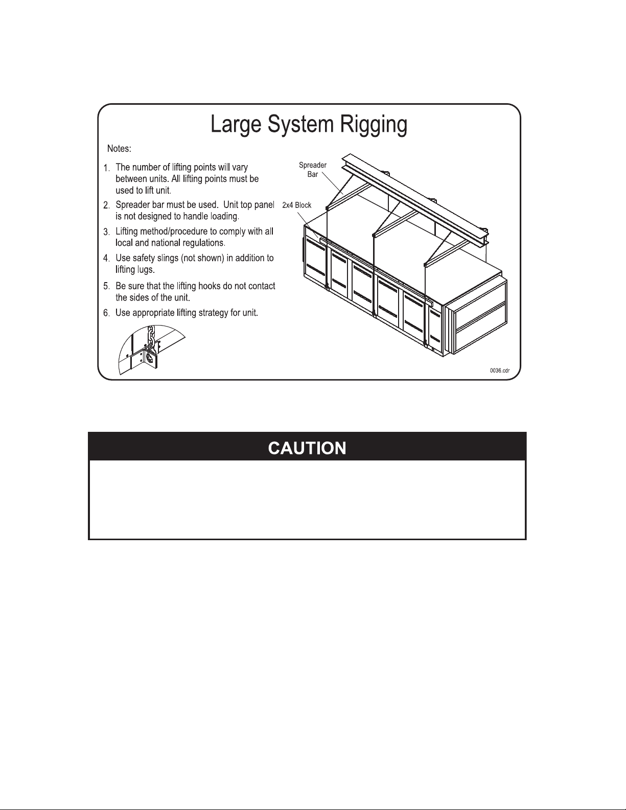
1.3 Rigging
1. Failure to observe rigging instructions may lead to equipment damage,
personal injury or death.
2. Lifting method and procedure must comply with all local and national codes
and regulations.
3. The use of safety slings in addition to lifting lugs is required.
4. Do not lift the dehumidifier in high winds or above people.
Desert Aire dehumidiers are solidly built and can be very heavy. Avoid personal injury and damaged
equipment by planning the installation carefully. Use moving equipment whenever possible.
1.3.1 RiggingtheDehumidier
Desert Aire dehumidiers are equipped with four or more lifting lugs. Use spreader bars and
safety straps when you use these lugs for rigging.
• Utilize all of the lifting lugs provided when hoisting unit.
• Test-lift the dehumidier to verify that it is properly balanced.
• Do not lift the dehumidier in high winds or above people.
• The top panels are not designed to support the weight of persons. The top panels are
weather proofed and excessive weight may cause water to penetrate through cracked
seams. Damage incurred through caved or distorted top panels will not be covered
under warranty. If you must walk on the top panels, carefully walk on the edges where
structural integrity is greatest.
14 Desert Aire - SP Manual
Figure 1 - Typical Rigging for the SP Dehumidier
1. Do not tip the dehumidifier on it’s side.
2. Avoid dropping the unit down stairways or subjecting it to severe
mechanical shock.

15
Desert Aire - SP Manual
2 Installation
Manualappliestostandardunitcongurationsonly.
2.1 Position and Service Clearance
Desert Aire dehumidiers require routine maintenance to operate efciently. Always refer to the General
Arrangement drawings for recommended clearance distances that are specic to your unit.
• Allow a minimum of 36 inches of clearance around the service side of the dehumidier for piping,
electrical connections, and service access. Install the unit on a sturdy, level mounting base or
platform that will prevent vibration and sound transmission. Never install the dehumidier on a
wooden platform without consulting the design engineer for spring isolation requirements and
sound control materials. Do not install the unit near occupied rooms such as ofces or guest
rooms.
• Level the dehumidier to ensure proper condensate drainage.
• Install blocks under the unit if necessary to provide clearance for the condensate trap. Install
blocks underneath each corner and each lifting lug.
Figure 2 - Dehumidier with Blocks Installed for Trap Clearance
• Install outdoor dehumidiers equipped with an outdoor air intake away from plumbing vents,
furnace ues, or equipment which could contaminate the air supply.
• If the dehumidier is to be mounted on a roof curb, make sure that the curb has been properly
mounted and supported. Place gasketing around the perimeter of the curb before setting the
dehumidier in place. This will help prevent air or water leaks.
• You must not install an indoor rated dehumidier in an unconditioned space or where ambient
temperatures can fall below 45°F. If you must install the dehumidier outside or in an
unconditioned space, you must use an outdoor rated dehumidier. Desert Aire equips
outdoor-rated units with weatherproong and thicker insulation. You can determine if your unit is
outdoor-rated by inspecting the unit rating plate. See Section 5.7 for details.
• Duct design and installation should conform to ASHRAE and SMACNA low velocity duct
standards. See Section 5.2 for additional duct recommendations.
16 Desert Aire - SP Manual
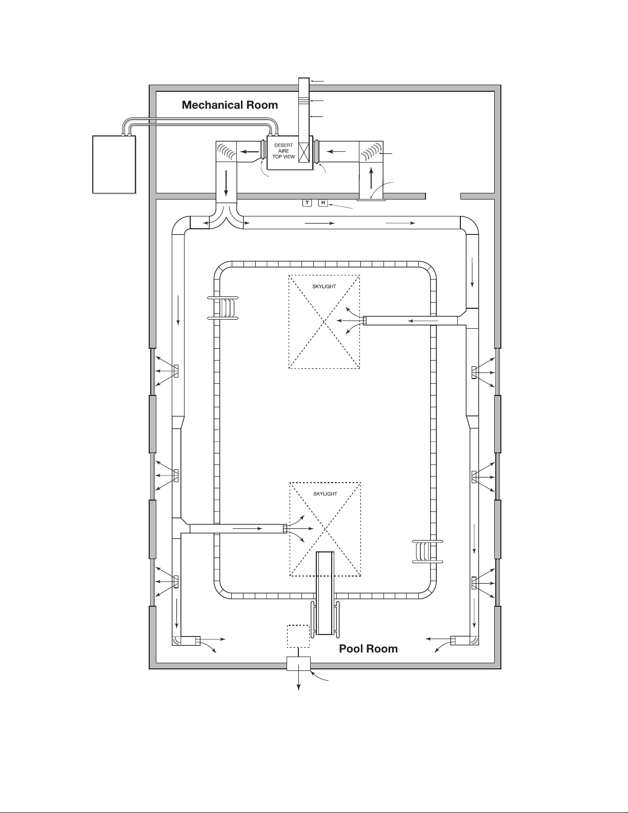
Figure 3 - Basic Pool Room Layout
FLEXIBLE NEOPRENE
DUCT CONNECTOR
LOCATE ANODIZED ALUMINUM
RETURN AIR GRILLE AS HIGH
AS POSSIBLE IN ROOM.
INSTALL TURNING VANES
IN ALL ELBOWS.
INSULATED OUTSIDE AIR INTAKE DUCT,
(SIZE FOR CODE REQUIREMENTS)
MOTOR OPERATED DAMPER
WEATHER-PROOF INTAKE HOOD
REMOTE
CONDENSER
TEMPERATURE AND HUMIDITY CONTROLS
MECHANICAL EXHAUST WITH BACK-DRAFT DAMPER
(WALL OR ROOF MOUNTED)
NOTE: CAPACITY SHOULD NOT EXCEED INTAKE VOLUME.
17
Desert Aire - SP Manual
Use turning vanes whenever the duct makes an abrupt turn, especially in the return air duct.
Poor return air distribution will reduce the moisture removal.
VAPOR BARRIER
AUX. HEATING
WINDOW
ANODIZED ALUMINUM
FLOOR DIFFUSERS
(SIZE FOR PROPER
AIR FLOW)
SUPPLY PIPING
LOOP SYSTEM
POOL
P.C.D. COATED SPIRAL
GALVANIZED PIPE
ANODIZED ALUMINUM
RETURN AIR GRILLE
LOCATE AS HIGH AS
POSSIBLE
RETURN AIR DUCT
DESERT AIRE DEHUMIDIFIER
FILTER RACK
FLEXIBLE DUCT
CONNECTIONS
POOL DECK
CONDENSATE PIPING
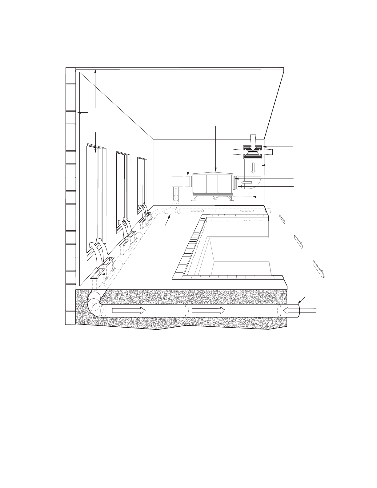
Figure 4 - Typical In-Ground Duct Layout
• You may use galvanized sheet metal ducts for all but underground installations and severely
corrosive environments.
• Do not use berglass duct boards or acoustic duct liner for air distribution in highly humid
applications, such as pool room dehumidication.
• If a duct must be installed in an unconditioned area, or if you are installing an outdoor air
intake duct, insulate it with two inches of berglass duct wrap with an intact vapor barrier.
• Direct the supply air toward skylights, exterior walls and windows, and spectator areas.
Since air movement will increase the evaporation rate of the pool, direct the supply air grilles
away from its surface.

18 Desert Aire - SP Manual
VAPOR BARRIER
MAIN SUPPLY
AIR DUCT
WINDOW
POOL
BRANCH SUPPLY AIR DUCT
ANODIZED ALUMINUM
RETURN AIR GRILLE
LOCATE AS HIGH AS POSSIBLE
RETURN AIR DUCT
DESERT AIRE DEHUMIDIFIER
SKYLIGHT
FLEXIBLE DUCT
CONNECTIONS
POOL DECK
ANODIZED ALUMINUM
CEILING DIFFUSER
ANODIZED ALUMINUM
SIDEWALL REGISTER
VAPOR BARRIER
Figure 5 - Soft Duct Layout with Skylight Grille
• Install return air grilles or louvers as high as possible in the enclosure. Normally, one
centrally-located grille will be adequate. Avoid under sizing this grille or “short-circuiting” of air
with nearby supply registers.
• Select grilles and diffusers for low static pressure loss and proper throw and CFM rating.
• Keep the noise criteria levels of the grilles between 35 and 45 dB.
• Use anodized aluminum grilles to prevent premature corrosion.

19
Desert Aire - SP Manual
2.2 Outdoor Air and Exhaust Air
Desert Aire SelectAire Plus™ dehumidiers are equipped with an opening which will draw outdoor air
into the conditioned space. This will help you comply with ASHRAE Standard 62, which requires the
introduction of outdoor air into commercial buildings.
Additionally, the SelectAire Plus™ unit is equipped with fans and dampers for exhausting air from the
building. This ensures that the building is at a negative static pressure relative to adjacent spaces and
outdoors.
Several modes may be available that provide for different outside air and exhaust ow rates. These
modes are Unoccupied mode, Occupied mode, Event mode, Purge mode and Max OA mode.
See Section 5.5.1 for more details. The ducting method you use depends on the SelectAire Plus™
type of dehumidier you purchased.
2.2.1 Units with Outdoor Air Only
A SelectAire Plus™ unit congured for indoor installation has a module which contains lters
and a factory-installed damper and actuator. The outdoor air is distributed between the
evaporator and the reheat condenser coils. The unit controller will energize dry contacts to
control any additional outdoor air dampers. This controller will also control the internal exhaust
fans. Figure 6 shows typical ducting for the SelectAire Plus™ unit congured for indoor
installation. The outdoor air duct used for indoor units must be insulated to prevent condensation
from forming on it during the winter. Since cold outdoor air can cause moisture to condensate
and freeze on surfaces when it mixes with the warm, humid return airstream, you must
preheat the outdoor air whenever possible.
When equipped for indoor installation the SelectAire Plus™ unit will also have a connection
exhaust air duct. The humid exhaust air may form an icy fog when it blasts outside during the
winter. Install the outlet grille in a location where this fog will not damage the building or create
a safety hazard. The SelectAire Plus™ has several options for location of the exhaust air
discharge. See submittal documentation and general arrangements for locations of connections
for a particular unit.

20 Desert Aire - SP Manual
Field-Installed Duct
Field-Installed
Duct
Figure 6 - Indoor Dehumidier Showing Outdoor Air and Exhaust Duct
A SelectAire Plus™ unit congured for outdoor installation has an outdoor air intake that is protected by
dual weather hoods. The unit controller will control the internal outdoor air damper and the exhaust
blower conguration. Dry contacts are available for control of eld supplied dampers.
An outdoor SelectAire Plus™ unit is also provided with an exhaust hood. This is shipped loose for eld
installation. See Section 2.16 for installation instructions.
Figure 7 - Outdoor Dehumidier
The outdoor air hoods are equipped standard with a wire mesh (bird screen) material attached to a rack
at the lower face of the hood. If needed, the rack can be removed from the hood for cleaning as an
assembly. There are several 1/4 – turn fasteners at the perimeter of the rack that can be removed. The
rack will then tilt downward and can be pulled out from the face of the cabinet.
Table of contents
Other Desert Aire Dehumidifier manuals


