Desert Aire Aura QS User manual

Installation and Operation Manual
• 100% Outdoor Air
Systems & High
Outdoor Air Systems
• Aura™ (QS), dedicated
outdoor air system,
offers a high quality
dehumidifier with
various options to
cover multiple
applications
• TotalAire™ (QS),
dedicated outdoor air
systems, offers an
optional energy
recovery wheel that
recovers both sensible
and latent heat.
• VerticalAire™ (QV),
dedicated outdoor air
system, is a high-
quality cost-effective
dehumidifier that’s
designed for tight
spaces
Indoor Air Quality
Aura™ (QS)
TotalAire™ (QS)
VerticalAire™ (QV)
TotalAire™ (QS)
Dehumidifier
VerticalAire™ (QV)
Dehumidifiers
Aura™ (QS)
Dehumidifier

2
3
Desert Aire - QS/QV Manual
DANGER
ONLY TRAINED, QUALIFIED PERSONNEL SHOULD INSTALL AND/OR SERVICE
DESERT AIRE EQUIPMENT. SERIOUS INJURY, DEATH AND PROPERTY DAMAGE CAN
RESULT FROM IMPROPER INSTALLATION/SERVICE OF THIS EQUIPMENT. HIGH VOLTAGE
ELECTRICAL COMPONENTS AND REFRIGERANT UNDER PRESSURE ARE PRESENT.
For any unit labeled Class 1, Group D, Division 2, all wiring must be in accordance to
Class 1, Group D, Division 2 requirements. Insure that all local, state, national and any
other applicable codes are adhered to when connecting any device to this equipment.
All electrical connections to units labeled Class 1, Group D, Division 2 must be done
with a conduit seal.
Desert Aire
Dehumidication Equipment Standard Limited Warranty
Desert Aire warrants the dehumidifying unit to be free from defects in materials and workmanship subject to the terms,
conditions and limitations stated herein.
TERMS
Desert Aire warrants all components (except as noted) for a period of two (2) years from the date of shipment. This
warranty shall be limited to the supply of new or rebuilt parts for the part which has failed because of
defects in workmanship or material, and does not include the cost for labor, transportation or other costs not herein
provided for. Replaced parts are warranted only for the remaining portion of the original warranty period.
CONDITIONS
The warranty is subject to the following conditions:
1. The unit must be properly installed and maintained in accordance with the Desert Aire
“Installation and Operation Manual” provided with each unit and/or other documentation provided.
2. The Start-Up Report must be completed and returned to Desert Aire Service for evaluation. If no
deciencies are identied a Warranty Validation Letter will be issued that provides all warranty dates
and coverage. If installation or start-up deciencies are present, these must be corrected and
communicated to Desert Aire in order to activate warranty.
3. This warranty shall not apply to any part that has been tampered with, or has been subject to
misuse, negligence or accident. A warranty can be obtained for altered equipment but only with
written consent from Desert Aire.
4. Thefollowingpartsandcomponentsareexcludedfromthewarranty:belts,lters,driers,fusesand
refrigerant.

4Desert Aire - QS/QV Manual
5. Refrigerant coils or other components that corrode due to improperly balanced pool chemistry or
corrosive air quality will not be warranted.
6. All replacements or repairs will be FOB Germantown, WI.
7. This warranty shall be null and void if defects or damages result from unauthorized opening of the
refrigerant circuit, tampering with factory set controls, or operating outside the original design conditions.
8. Desert Aire shall not be liable for labor costs incurred in diagnosing the problem, or the removal
or replacement of the part or parts being repaired.
9. Desert Aire must preauthorize all warranty coverage described herein.
Extended Warranty:
Your Desert Aire unit may have extended warrantees beyond this Standard Limited Warranty document.
Extended warrantees are only available at the time of the purchase of the original equipment. These extended
warrantees are covered under a separate document and their terms and conditions are separate from this
document. It is mentioned in this document for informational purposes only. Any Extended Warranties will be
identiedontheWarrantyValidationletter.
Any and all incidental or consequential damages are expressly excluded from this warranty. Some states do not allow
the exclusion of incidental or consequential damages for personal injury, so the above limitations may not apply to you
for certain damages. This warranty gives you specic legal rights, and you may also have other rights, which vary
from state to state. No person or representative is authorized to make any warranty or assume any liability not strictly
in accordance with the aforementioned.
Inquiries regarding warranty matters should be addressed to:
Desert Aire Corp c/o Service Manager
N120 W18485 Freistadt Road • Germantown, WI 53022
Additional copies of this manual can be purchased for a nominal fee from Desert Aire. Desert Aire also posts the most
current revision of our I/O Manuals on our website. For a digital copy of the I/O Manual for your unit revision, please
submit request to the contact information listed above.
Gas Heat Exchanger Ten (10)-Year Prorated Warranty Terms (For Aura™ units with gas heat only)
Desert Aire offers an extended prorated eight (8)-year warranty for gas heat exchanger. All other heater components
are covered under the initial 2 year warranty.
2 Years Parts Only from date of shipment. Prorated from years 3-9 as follows:
Year 3: Desert Aire warrants 70% of replacement price
Year 4: Desert Aire warrants 60% of replacement price
Year 5: Desert Aire warrants 50% of replacement price
Year 6: Desert Aire warrants 40% of replacement price
Year 7: Desert Aire warrants 30% of replacement price
Year 8: Desert Aire warrants 20% of replacement price
Year 9: Desert Aire warrants 10% of replacement price
5
For Units w/Gas Heat:
For Your Safety Read Before Operating
WARNING: If you do not follow these instructions exactly a fire or explosion
may result causing property damage, personal injury or loss of life.
A. This appliance does not have a pilot. It is equipped with an ignition device that automatically
lights the burner. Do not try to light the burner by hand.
B. BEFORE OPERATING smell all around the appliance area for gas. Be sure to smell next to the
floor because some gas is heavier than air and will settle on the floor.
WHAT TO DO IF YOU SMELL GAS
• Do not try to light any appliance.
• Do not touch any electric switch; do not use any phone in your building. Immediately call
your gas supplier from a neighbor’s phone. Follow the gas supplier’s instructions.
• If you cannot reach your gas supplier, call the fire department.
C. Use only your hand to push in or turn the gas control knob. Never use tools. If the knob will
not push in or turn by hand, don't try to repair it, call a qualified service technician.
Force or attempted repair may result in a fire or explosion.
D. Do not use this appliance if any part has been under water. Immediately call a qualified service
technician to inspect the appliance and to replace any part of the control system and any gas
control that has been under water.
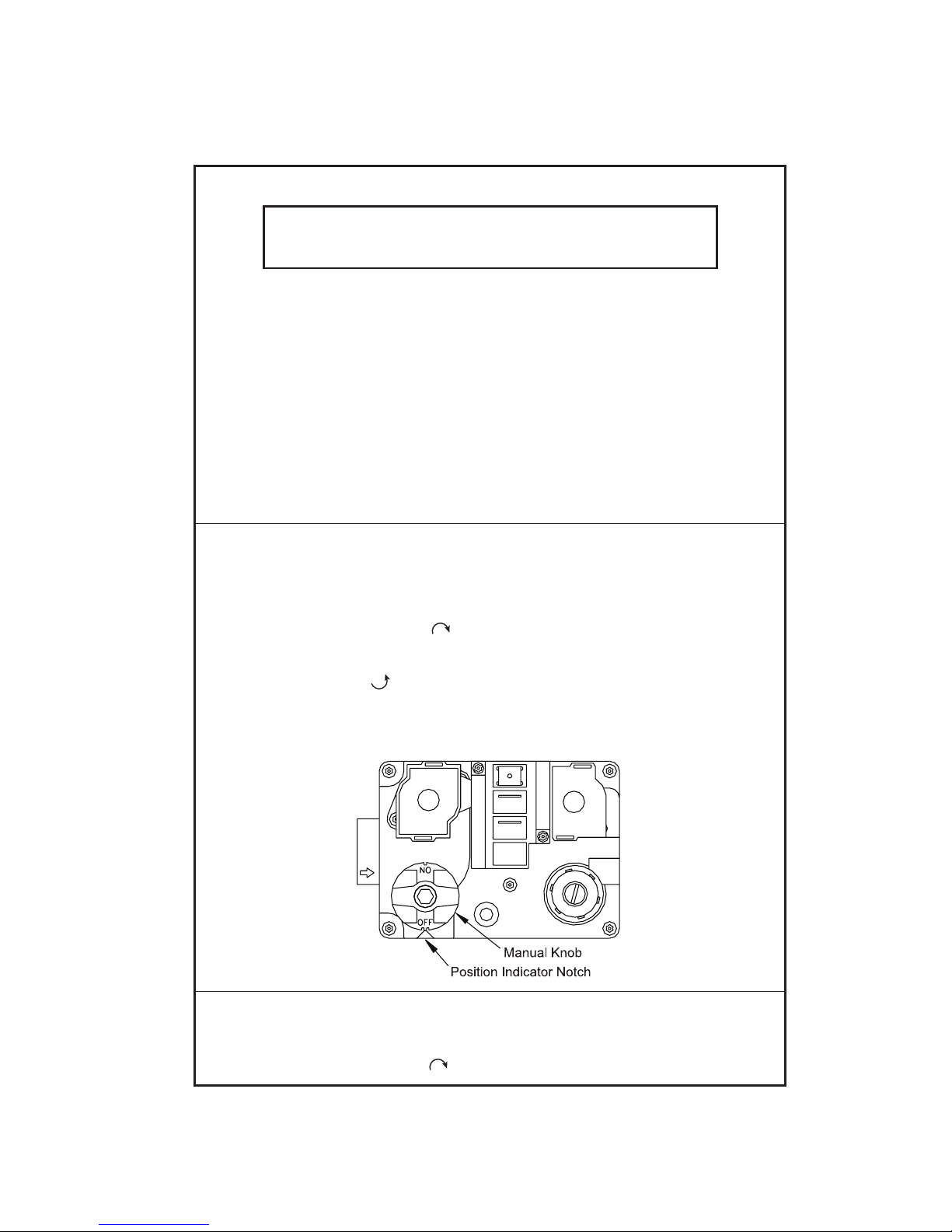
OPERATING INSTRUCTIONS
1. STOP! Read the safety information above on this label.
2. Set the thermostat to lowest setting.
3. Turn off all electric power to the appliance.
4. This appliance is equipped with an ignition device that automatically lights the burner.
Do not try to light the burner by hand.
5. Turn gas control knob clockwise to "OFF" position.
6. Wait five (5) minutes to clear out any gas. Then smell for gas, including near the floor.
If you smell gas, STOP! Follow "B" in the safety information above on this label. If you don't
smell gas, go to next step.
7. Turn gas control knob counterclockwise to "ON" position.
8. Turn on all electric power to unit.
9. Set thermostat to desired setting.
10. If appliance will not operate, follow the instructions “To Turn Off Gas To Appliance” and call
your service technician or gas supplier.
TO TURN OFF GAS TO APPLIANCE
1. Set thermostat to lowest setting.
2. Turn off all electric power to the appliance if service is to be performed.
3. Turn gas control knob clockwise to "OFF" position.
Desert Aire - QS/QV Manual

6
Safety Labels are used throughout this manual. They comply with the ANSI Z535.4 Standard.
Please be familiar with the following labels and their denitions.
This is the safety alert symbol. It is used to alert you to potential
personal injury hazards. Obey all safety messages that follow this
symbol to avoid possible death or injury.
Indicates an imminently hazardous situation which, if not
avoided, will result in death or serious injury.
Indicates a potentially hazardous situation which, if not
avoided, could result in death or serious injury.
Indicates a potentially hazardous situation which, if not
avoided, could result in minor or moderate injury.
Caution used without the safety alert symbol indicates a
potentially hazardous situation which, if not avoided, could
result in property damage.
Product Warning for the State of California
Desert Aire - QS/QV Manual

7
TABLE OF CONTENTS
1. Introduction ................................................................................................................................. 9
1.1. Inspection ...................................................................................................................... 9
1.2. Freight Damage Claims ................................................................................................. 9
1.3. Rigging .......................................................................................................................... 9
1.3.1.RiggingtheDehumidier................................................................................... 9
2. Installation
..................................................................................................................................
13
2.1. LocationofDehumidier................................................................................................ 13
2.2. Duct Installation ............................................................................................................ 14
2.3. Condensate Drain Piping .............................................................................................. 14
2.4. Auxiliary Heat Coil Piping .............................................................................................. 16
2.5. Water Piping Installation (for Q-Pump and Water-Cooled Systems Only) .................... 16
2.6. Remote Condenser Installation (Air-Cooled Systems Only) .......................................... 19
2.7. High Voltage Wiring
......................................................................................................
20
2.7.1. High Voltage Connections ................................................................................. 20
2.7.2. Wire and Fuse Sizing ........................................................................................ 21
2.8. Controls and Sensors
...................................................................................................
21
2.8.1. Duct-Mount Sensor ........................................................................................... 22
2.8.2. Remote Room Sensor(s) ................................................................................... 22
2.8.3. CO2Sensors ...................................................................................................... 22
2.9. Auxiliary Heating Control Wiring
...................................................................................
22
2.9.1. Auxiliary Heating - Dry Contact Closure .......................................................... 22
2.9.2. Auxiliary Heating - Proportional Signal ............................................................ 22
2.10. Gas Heater (Optional) ................................................................................................... 23
2.10.1. Gas Heater Installation ................................................................................... 23
2.10.2. Gas Piping ...................................................................................................... 24
2.10.3. Gas Heater Location ........................................................................................ 30
2.11. Electric Heater (Optional) .............................................................................................. 33
2.12. Auxiliary Heat Coil Piping (Optional) ............................................................................. 33
2.13. Smoke Alarm Interlock .................................................................................................. 34
2.14. Cover Plates (if applicable) ........................................................................................... 34
2.15. Roof Curb w/ Wood Nailer (if applicable) ...................................................................... 35
2.16. Wheel Module Installation (Optional for Aura™ Products) ............................................ 36
3. Start-Up Procedures ................................................................................................................... 37
3.1. Preliminary Inspection ................................................................................................... 37
3.2. Gas Heater Start-Up (Optional) ..................................................................................... 38
3.2.1. Burner Adjustment .......................................................................................... 40
3.3. AirowBalancing........................................................................................................... 40
3.3.1. Blower Adjustment Procedure ........................................................................ 41
3.3.1.1 Units with an EC Blower .................................................................. 41
3.3.1.2 Units without a VFD ......................................................................... 41
3.3.1.3 Unit with a VFD ................................................................................ 42
3.3.2. AirowBalancingforDedicatedOutsideAirSystems(DOAS)....................... 42
3.3.2.1 Aura™ and TotalAire™ Units .......................................................... 43
3.3.2.2 AirowBalancingforQVDehumidiers.......................................... 44
3.3.2.2.1 Damper Box Equipped VerticalAire™ Systems .................. 47
3.3.3. AirowBalancingforDedicatedOutdoorAirSystems(DOAS)with
Unoccupied Recirculation ................................................................................ 47
3.3.4. AirowBalancingforHighOutdoorAirSystems(HOAS)............................... 48
3.3.4.1 For Units with External Enthalpy Wheel (Aura™) ........................... 49
3.3.4.2 For Units with CO2Control (Aura™) ............................................... 49
Desert Aire - QS/QV Manual

8Desert Aire - QS/QV Manual
3.3.4.3 Recirculation Mode (TotalAire™) .................................................... 50
3.3.4.4 Mixed Air Mode (TotalAire™) .......................................................... 50
3.3.4.5 For Units with Systems Equipped with Demand Controlled
Ventilation Option (TotalAire™) ....................................................... 50
3.3.4.5.1UnoccupiedModewithRecirculation(whenspecied)
(TotalAire™) .................................................................. 51
3.3.4.5.2 Occupied Mode Minimum Outdoor Air (TotalAire™) ...... 51
3.3.4.5.3 Occupied Mode Maximum Outdoor Air (TotalAire™) ..... 52
3.4. Refrigeration Testing ...................................................................................................... 53
3.4.1. Dehumidication/CoolingMode.................................................................... 54
3.4.2. Heat Pump Mode ............................................................................................ 55
3.5. General Testing
............................................................................................................
57
3.6. Routine Maintenance Schedule
..................................................................................
57
3.6.1. Service Every Month ........................................................................................ 57
3.6.2. Service Every Six Months ..................................................................
..............
58
3.6.3. Service Every Year .............................................................
..............................
58
3.6.3.1 Energy Recovery Wheel (Optional)
........................
........................... 58
3.6.3.2 Gas Heater (Optional) ..................................
.......................................
59
4. Troubleshooting
........................................................................................................
..................
61
4.1. The Blower Does Not Run ............................................................................................. 61
4.2. The Compressor(s) Do Not Run .................................................................................... 62
4.3. High Pressure Alarms / Readings Above High Pressure Trip Set Point ...
......................
62
4.4. Low Pressure Alarms (Below 97 PSIG) Evaporator Coil Icing ................
.......................
63
5. Appendix
......................................................................
................................................................
65
5.1. Compressor Failure ................
........................................................................................
65
5.1.1. Compressor Replacement ............................................................................... 65
5.2. Recommended Duct Design
..........................................................................................
69
5.3. Recommended Controller Settings
................................................................................
70
5.4. IAQ Sequence of Operation
...........................................................................................
70
5.4.1. Basic Sequence
..............................................................................................
70
5.4.2. Blower Operation ............................................................................................. 71
5.4.3. DehumidicationOperation............................................................................... 72
5.4.3.1. Packaged Units .................................................................................. 72
5.4.3.2. Q-Pump Inverter + Units .................................................................... 72
5.4.4. Cooling Operation ................................................................
............................
73
5.4.4.1. Packaged Units .................................................................................. 73
5.4.4.2. Q-Pump Inverter + Units .................................................................... 73
5.4.5. Heating Operation ........................................................................
...................
. 74
5.4.5.1 Water Source Heat Pump .................
.............................................
.. 74
5.4.5.2 Auxiliary Heat ..........................................................
.......................
... 75
5.4.6. SAT Control Options ........................................................................................ 75
5.4.7. Compressor Rotation ...................................................
.........................
........... 75
5.4.8. CO2Operation ..........................................................
..............................
.......... 76
5.4.9. Suction Pressure Operation ................................................
.............................
76
5.4.10. Enthalpy Wheel Operation ..............................................................
.................
77
5.5. Component Replacement, Charge, Evacuation, & Leak Instructions ..........
..................
77
5.6. System Rating Plate ...................................................................................................... 82
5.7. Start-Up Supervision Supplemental Information
...........................................................
83
5.8. System Start-Up Report
..................................................................
..............................
83
Start-Up Request Form ................................................................................................ 84
Start-Up Report
.............................................................................
................................
86
Compressor Replacement Form
...................................................
................................
91
9
1. Introduction
DesertAiredehumidiersaredesignedtoprovideyearsofreliableservicewheninstalled
properly.Readtheseinstructionscarefullybeforeyouinstallthedehumidier.
1.1. Inspection
DesertAireinspectsandtestseachdehumidierbeforeitleavesthefactorysothat
you receive a quality piece of equipment. Unfortunately, equipment may become
damagedintransit.Inspectthedehumidiercarefullybeforesigningthereceiving
papers. Check for both visible and concealed damage. Remove crating and inspect
theexteriorcabinetfordamage.Dentedpanels,brokencratingoranyuidleakingfrom
the unit should be documented upon delivery.
1.2. Freight Damage Claims
Ifthedehumidierhasbeendamaged,documenttheextentofthedamage.Takepicturesif
possible.Next,obtainaclaimformfromthecarrier.Promptlylloutandreturntheform.
Carriersmaydenyclaimsthatyouhavenotlledoutwithinaweekofdelivery.NotifyDesertAire
of any damage. Damaged units must have signed documents at the time of delivery to be eligible
for a freight claim.
1.3. Rigging
1. Failure to observe rigging instructions may lead to equipment damage, personal
injury, or death.
2. Lifting method and procedure must comply with all local and national codes and
regulations.
3. The use of safety slings in addition to lifting lugs is required.
4. Do not lift the dehumidifier in high winds or above people.
DesertAiredehumidiersaresolidlybuiltandcanbeveryheavy.Avoidpersonalinjuryand
damaging the equipment by planning the installation carefully. Use moving equipment whenever
possible.
1.3.1. Rigging the Dehumidier
Depending upon the unit type, various rigging methods are used to best lift the
equipment. Please reference the applicable sections below:
Desert Aire - QS/QV Manual

10
• All Products (QV and QS)
Personnel should avoid stepping on the top of the unit. Desert Aire
dehumidiersarenotdesignedtosupporttheweightofapersononall
portions of the roof. Damage incurred through caved or distorted top panels
will not be covered under warranty. If you must walk on the top panels,
carefully walk on the edges where structural integrity is greatest.
• VerticalAire™ Products (QV)
- 4-15 Ton
Move the unit to the desired installation location with the unit on the
wood skid. To remove unit from skid, position fork lift parallel to the
boards on the top of the skid. Carefully slide forks between the unit
and cross braces to pick the unit off the skid. The unit will have to be
carefully removed from the fork lift and placed into the desired
location using hand truck equipment dollies or pipe rollers. Use
caution to not damage the unit with the fork lift or tip the unit over
ensuring it is kept as level as possible.
- 20-30 Ton
The base is equipped with a built-in 12 gauge skid. Use a fork lift to
move the unit into place. Use caution to not damage the unit with the
fork lift or tip the unit over ensuring it is kept as level as possible. In all
cases, use appropriate safety practices while lifting the unit. Forklift
tie-down clamps, straps, and other restraints where applicable should
be used to prevent tipping of the load.
• Aura™ and TotalAire™ Products (QS)
Aura™andTotalAire™dehumidiersareequippedwithfourormorelifting
points. Use spreader bars and safety straps when you rig the equipment.
- Utilize all of the lifting lugs provided when hoisting the unit.
- Test-liftthedehumidiertoverifythatitisproperlybalanced.
- Refer to diagram below for additional lifting instructions.
Desert Aire - QS/QV Manual

11
Figure 1 - Typical Rigging for an IAQ Dehumidier
1. Do not tip the dehumidifier on its side.
2. Avoid dropping the unit down stairways or subjecting it to severe mechanical shock.
Desert Aire - QS/QV Manual

12 Desert Aire - QS/QV Manual

13
2 Installation
Manual applies to standard unit congurations only.
2.1 Location of Dehumidier
DesertAireTotalAire™dehumidiersareconguredtoallowsingle-sideaccess.Thismeans
you can make your service connections and perform routine maintenance when you must install
onesideofthedehumidierclosetoawallorotherrestriction.The“serviceside”isdetermined
whentheorderisplacedatthefactoryandcannotbechangedintheeld.Itisrecommended
that clearance be provided on all sides to allow for ease of serviceability in the event large
components require replacement. Aura™ and VerticalAire™ units may require service access
from multiple sides. Refer to the general arrangement drawing for further details.
Allowaminimumof36inchesofclearancearoundtheservicesideofthedehumidierforpiping,
electrical connections, and service access. The non-access side of the unit should contain 12
inches of clearance for large component removal. A minimum one unit width clearance shall be
maintained in all directions of outside air intake hood on outdoor units to allow for un-obstructed
airowintotheunit.Forpackagedunits,ensureaminimumofoneunitwidthofclearanceis
maintainedtoallowforproperairowthroughthecondensingsection.Ifthreeormorewalls
surroundtheunitconsultthefactoryforproperunitlocationtoallowforadequateairowthrough
the condenser section.
Install the unit on a sturdy, level mounting base or platform that will prevent vibration and sound
transmission.Neverinstallthedehumidieronawoodenormetalplatformwithoutconsulting
the design engineer for spring isolation requirements and sound control materials. Do not install
theunitnearoccupiedroomssuchasofcesorguestrooms.Donotattempttoconserve
installation space by fabricating restrictive ductwork with abrupt bends. You may reduce the
operatingefciencyandthemoistureremovalcapacityofthedehumidier.Seesection5.2for
detailed duct installation instructions.
Units located in unconditioned spaces may form condensation on the exterior of the cabinet.
Precautions should be taken for indoor units located within unconditioned spaces to prevent
damage resulting from condensation.
Do not install an indoor-rated dehumidier in an outdoor or a wet environment.
Ifyoumustinstalladehumidieroutsideyoumustuseanoutdoor-rateddehumidier.Desert
Airesealsandweatherproofsoutdoordehumidierstohelppreventwaterinltration.Youcan
determinewhetheryourdehumidierisoutdoor-ratedbyinspectingtheunitratingplate.
See section 5.6 for details.
Desert Aire - QS/QV Manual
14
2.2 Duct Installation
Duct design and installation should conform to the latest ASHRAE and SMACNA low velocity
duct standards. See section 5.2 for details. Undersized, restrictive ductwork with abrupt turns
ortransitions,candecreasetheefciencyandthemoistureremovalcapacityofyour
dehumidier.Sizetheductworkforanacceptableairpressuredropattheairowvolumeof
yourdehumidier.Useneopreneexconnectorswhenyouattachductworktothedehumidier
to prevent transmission of excess vibration and noise.
Select the grilles, registers and diffusers for low static pressure loss, required throw distance,
andthespeciedCFMrating.Youcanndthisinformationinmostgrillemanufacturer’s
catalogs. If you are installing the grilles in a corrosive environment, choose components made
from anodized aluminum.
Ifyoumustinstallductworkinanunconditionedarea,useberglassductwrapwithvapor
barrier facing. You must install the outdoor air intake away from all sources of airborne
contamination such as exhaust fans or plumbing vents. You can use galvanized sheet metal
ducts for most applications. However, you should use aluminum or stainless steel ducts for
extreme applications such as chemical-laden environments.
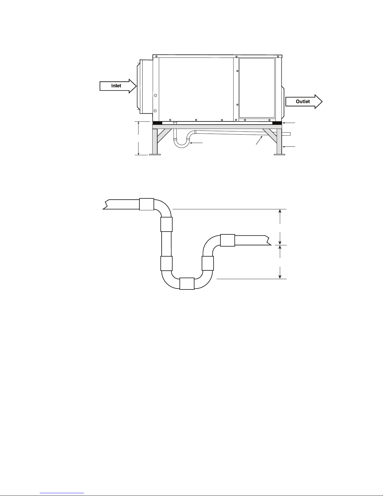
2.3 Condensate Drain Piping
Condensate drain lines installed in an unconditioned space must be heat taped to
prevent freezing. Check the heat tape yearly before winter operation.
Thecondensatedrainconnectionmaybeonthesideorthebottomofthedehumidier,
depending on the size and style of the cabinet used. Use concrete blocks or steel dunnage to
raisethedehumidierhighenoughabovetheoortoprovideclearancefortheeld-supplied
condensate drain trap.
Note:Dehumidierswithgasheatingoptionmayhavecondensateforminsidethefurnaceheat
exchanger since it is located downstream from the cooling coil. On indoor units, you must also
connecttheheater’sdrainline(ifpresent)toyoureld-installedcondensatedrainageplumbing.
Note:Whilethesupplyblowerruns,thedrainpanareainsidethedehumidieroperatesata
negative pressure. Your unit requires a p-trap in the condensate drain pipe to prevent
condensatefrombeingdrawnintothecabinetofthedehumidier.
Desert Aire - QS/QV Manual
15
Min. 12”
P-Trap (By Others)
Vibration
Isolator
Base /Support
(By Others)
1/4” Slope
Per Foot
Figure 2 - Condensate Piping (Bottom-Mounted Drain Shown)
4”
4”
Figure 3 - Sectional View of Condensate Trap Requirements
Trap the condensate as shown in Figure 3. The P-trap dimensions in Figure 3 are sized for a
maximumreturnairstaticof2.0”ofwater.Ifyourreturnairstaticexceedsthisspecication,
consult Desert Aire for help in resizing the P-trap.
You may also need to install a cleanout tee or plug near the trap. Note that the drain opening
in the drain pan is off-center to simplify its cleaning and servicing. Once you have designed
and installed the trap, follow this sequence:
1. Connect the trap to a main drain line with 1/4” of downward pitch per linear foot of run.
2. Supportthedrainpipeeveryvefeettopreventsagging.
3. After you install the drain piping, prime the trap by pouring water into the drain pan of
thedehumidier.
Desert Aire - QS/QV Manual

16
2.4 Auxiliary Heat Coil Piping
TheDesertAiredehumidiermaybeequippedwithanoptionalhotwaterorsteamairheating
coil. This coil, when properly sized, will provide space heating during the winter months.
Use proper practice when designing and installing the coil piping to prevent poor coil
performance, shortened service life, or damage to the coil.
• The supply connections must not be supported by the coil headers.
• Thecontrolvalveshouldbesizedaccordingtothepressureandowrate
requirements, not by the coil connection size.
• On steam systems, use strainers, dirt pockets, and isolation valves to prevent clogging
the control valve and to simplify service.
• Install swing joints in the connection piping to prevent damage to the coil header from
thermal expansion.
• Use a backup wrench on the pipe stubs when attaching connections to prevent
damage to the header.
2.5 Water Piping Installation (for Q-Pump and Water Cooled Systems Only)
Asanoption,thedehumidiermaybeequippedwithatowerwateroraheatpumploop
condenser.Useindustrystandardpipingpracticeswhenconnectingtosuchadehumidier.
Connectionsarecopperstubs.Refertosubmittaldocumentationforspecicsizepermodel.
Water Quality and General System Design
A60meshornerstrainermustbeinstalledinthewaterinletline.Flusheldinstalledpiping
thoroughlybeforeyouputthedehumidierintoservice.Apipingsystemnotproperlyushedor
lteredwillcausethebrazed-plateheatexchangertoloseefciencyorfailprematurelydueto
clogging and/or fouling.
To prevent premature failure of the heat exchanger, maintain the water at a pH of 7.4, but
never below 6.0. Do not use water with high concentration of sulfur, chlorine, or sodium
chloride.
A dedicated circulating pump must be used unless the main pump can develop enough head
to overcome the combined resistance of the water condenser and the piping connected to it.
SeespecicFlowRatesectionfortherequiredwaterowrateandheadforyourapplication.
Desert Aire - QS/QV Manual

17
Install an air eliminator at any high point in the water piping. Air trapped in the water circuit
ofthedehumidiercanleadtoelevatedoperatingpressures,unexpectedservicecalls,and
decreased equipment life.
If the water system is connected to a variable frequency drive or to water loops with multiple
units,owregulatingvalvesshouldbeinstalledtoensureowrateismaintained.
Do not exceed these guidelines as excessive flow rates will erode the condenser and piping.
Aura™ Products Flow Rate
Theowrateandantifreezeconcentration(ifused)willdependontheapplication.Pleaserefer
toFigure4and5fortherequiredowrateandtemperaturelimitsforthegivenapplicationand
unit type. If the application deviates from these conditions, please contact Desert Aire Service
at 262-946-7400 for further review.
Unit Size
(Nom. Tons)
8
10
12
15
20
25
30
Fluid Flow Rate
(GPM)
24
30
36
45
60
75
90
Fluid Pressure Drop
(psig)
4.0
5.6
4.1
3.6
3.4
6.4
4.0
Figure 4- Aura™ Q-Pump Water Flow Rates
Desert Aire - QS/QV Manual

18
Glycol Percent
0
5
10
15
20
25
30
35
40
45
50
Min. Fluid Temp. (°F)
40
37
34
31
27
25
25
25
25
25
25
Figure 5 - Aura™ Q-Pump Minimum Water Temperature
TotalAire™ and VerticalAire™ Products Flow Rate
Theowrateandantifreezeconcentration(ifused)willdependontheapplication.PleaserefertoFigure6
and7fortherequiredowrateandtemperaturelimitsforthegivenapplicationandunittypeaswellasthe
glycol concentration requirements. If the application exceeds these conditions, please contact Desert Aire
Service at 262-946-7400 for further review.
Desert Aire - QS/QV Manual

19
Unit Size
(Nom. Tons)
2
3
4
5
8
10
15
20
25
30
36
40
46
50
56
60
Fluid Flow Rate
(GPM)
9
15
15
19
20
28
45
57
70
87
99
123
135
143
156
172
Water Cooled Units
0.9
1.3
1.7
2.6
2.3
2.8
2.7
2.7
2.7
2.8
3.1
2.8
2.8
3.1
3.1
3.1
Q-Pump™ Units
2.3
2.9
4.2
6.3
5.5
6.5
6.3
6.2
6.2
6.4
6.5
6.5
6.4
6.5
6.4
6.5
Fluid Pressure Drop (psig)
Notes: Boiler/Tower loop temperature range must be pure water
between 55°F & 95°F
Ground source loop temperature range must be 30% glycol
between 35°F & 105°F
Figure 6 - Water Flow Rates
Glycol Percent
0
5
10
15
20 and up
Min. Entering Water Temperature (°F)
48
47
45
40
35
Figure 7 - Glycol Concentration Requirements
2.6 Remote Condenser Installation (Air-Cooled Systems Only)
Important: Refer to the separate Air Cooled Condensers Installation and Operation manual for
additional details on line design, traps, clamping, and other condenser installation requirements.
Desert Aire - QS/QV Manual
20
TotalAireandVerticalAiredehumidiersinstalledwithremotecondensersmayrequireadditional
oilandrefrigerantchargeatthetimeofeldinstallation.Refertothesubmittaldocumentationor
labeladjacenttotheremotecondenserconnectionstoconrmthechargeandconnectiontubesizes.
2.7 High Voltage Wiring
1. Disconnect power before servicing. The unit contains high voltage wiring and
moving parts which may cause serious injury or death.
2. Failure to properly wire the dehumidifier may create the possibility of shock and
can lead to premature system failure.
For any unit labeled Class 1, Group D, Division 2, all wiring must be in accordance to
Class 1, Group D, Division 2 requirements. Insure that all local, state, national and any
other applicable codes are adhered to when connecting any device to this equipment.
All electrical connections to units labeled Class 1, Group D, Division 2 must be done
with a conduit seal.
Electrical wiring must comply with all national, state, and local codes. Refer to the wiring
diagram located inside the electrical section for all wiring connections. To connect main power,
attach the supply wires to the three-pole power block mounted on the electrical panel. Test the
phasing by “bumping” the blower contactor. Verify that the blower rotates in the proper
direction. If it rotates the wrong direction, switch any two of the three wires at the power block.
2.7.1 High Voltage Connections
On single phase units the power supply must have 3 connections (2 power and 1
ground). On three phase units the power supply must have 4 connections (3 power
and 1 ground). Connect the power supply wires to the main power block located in the
upper section of the electrical compartment.
Desert Aire - QS/QV Manual
This manual suits for next models
2
Table of contents
Other Desert Aire Dehumidifier manuals


