designer's image 422784 User manual
Need help? Visit Sauder.com to view video assembly tips or chat with a live rep.
Prefer the phone? Call 1-800-445-1527.
Share your journey!
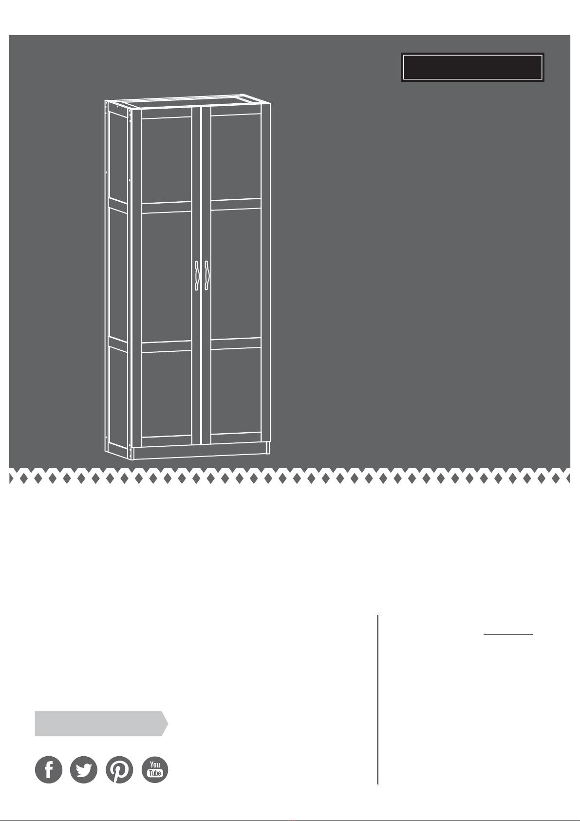
Storage Cabinet
Model 422784
NOTE: THIS INSTRUCTION
BOOKLET CONTAINS IMPORTANT
SAFETY INFORMATION.
PLEASE READ AND KEEP FOR
FUTURE REFERENCE.
English pg 1-18
Français pg 19-21
Español pg 22-24
Lot #: 511090
Date Purchased: __________________
12/08/17
Be sure to give us a ring before
making any returns. 1-800-445-1527
Store behind
closed doors.
DESIGNER’S IMAGE®

Table of Contents Assembly Tools Required
Part Identification
Hardware Identification
Assembly Steps
Français
Español
Safety
Warranty
Hammer
Not actual size
No. 2 Phillips Screwdriver
Tip Shown Actual Size
2-3
4
5-18
19-21
22-24
25-26
27
A RIGHT END (1)
B LEFT END (1)
C UPRIGHT (1)
D TOP (1)
E BOTTOM (1)
F SHELF (1)
G2 BACK (1)
H RIGHT DOOR (1)
I LEFT DOOR (1)
J ADJUSTABLE SHELF (4)
K VALANCE (2)
L SKIRT (1)
åWhile not all parts are labeled, some of the parts will have a label or an inked letter on the edge
to help distinguish similar parts from each other. Use this part identification to help identify similar parts.
Now you know
our ABCs.
Part Identification
Page 2 www.sauder.com 422784
Skip the power trip.
This time.
Tape Measure

Part Identification
Page 3
www.sauder.com422784
A
B
C
D
E
F
G2
H
I
J
K
L
J
J
J
K
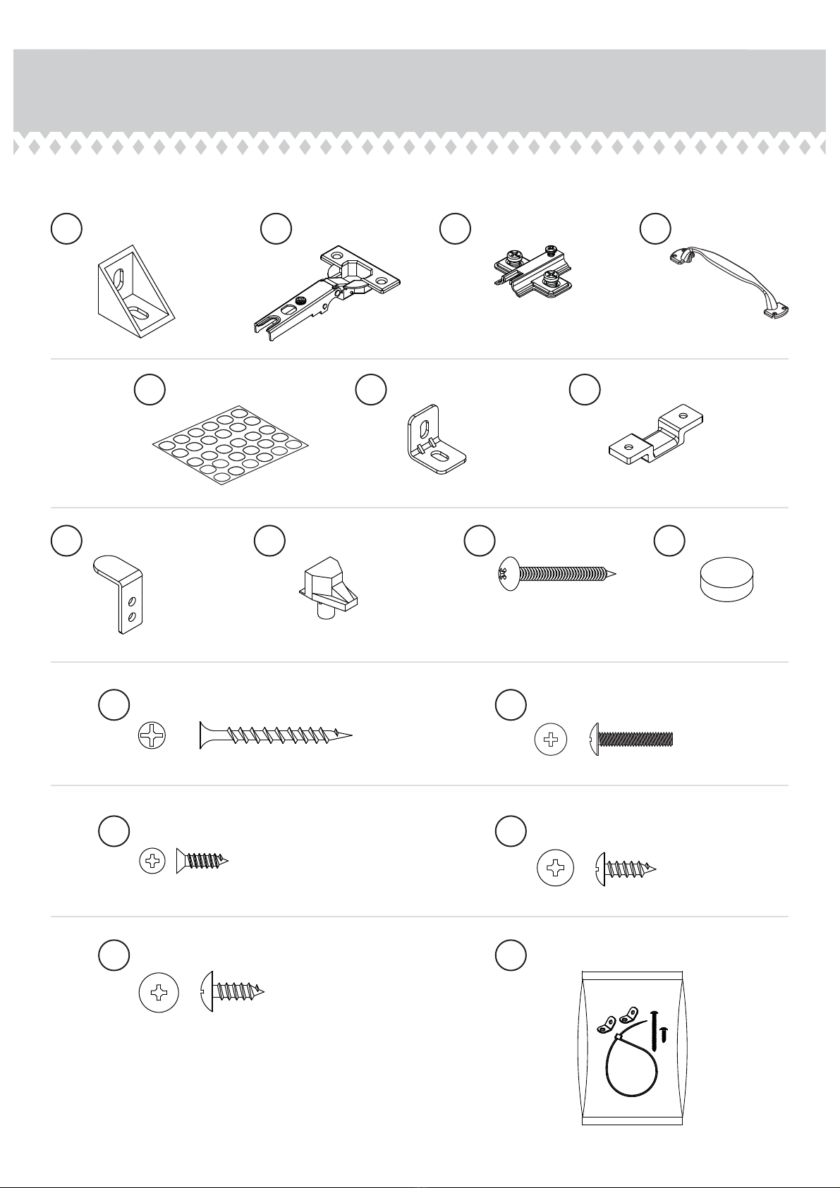
Hardware Identification
åScrews are shown actual size. You may receive extra hardware with your unit.
Page 4 www.sauder.com 422784
1/2" PAN HEAD SCREW - 8
18
1/2" FLAT HEAD SCREW - 12
17
ANGLE BRACKET - 5
1HINGE - 6
2HINGE BRACKET - 6
3
NAIL - 36
12
PULL - 2
4
APPLIQUE - 30
7METAL BRACKET - 2
8BOTTOM BRACKET - 1
9
DOOR BRACKET - 1
10 SHELF SUPPORT - 16
11
1-1/2" FLAT HEAD SCREW - 40
13 3/4" MACHINE SCREW - 4
15
FURNITURE TIPPING RESTRAINT KIT - 1
99
FELT DISC - 4
20
LARGE 1/2" PAN HEAD SCREW - 10
19
Step 1 Look for this icon. It means a
video assembly tip is available at
www.sauder.com/services/tips
å Assemble your unit on a carpeted floor or on the empty
carton to avoid scratching your unit or the floor.
å Fasten five ANGLE BRACKETS (1) to the SKIRT (L). Use
five LARGE 1/2" PAN HEAD SCREWS (19).
å NOTE: Be sure the edges of the ANGLE BRACKETS are
even with the edges of the SKIRT.
å Fasten the BOTTOM BRACKET (9) to the BOTTOM (E).
Use two 1/2" PAN HEAD SCREWS (18).
1
1/2" PAN HEAD SCREW
(2 used in this step)
18
L
1
1
E
9
The molding on the other surface
of the BOTTOM should be here.
Page 5
www.sauder.com422784
LARGE 1/2" PAN HEAD SCREW
(5 used for the ANGLE BRACKETS)
19
å Fasten the SKIRT (L) to the BOTTOM (E). Use three
LARGE 1/2" PAN HEAD SCREWS (19) through the ANGLE
BRACKETS on the VALANCE and into the BOTTOM.
Step 2
L
E
The molding on the
BOTTOM should be here.
Page 6 www.sauder.com 422784
LARGE 1/2" PAN HEAD SCREW
(3 used in this step)
19

FRONT
FRONT
FRONT
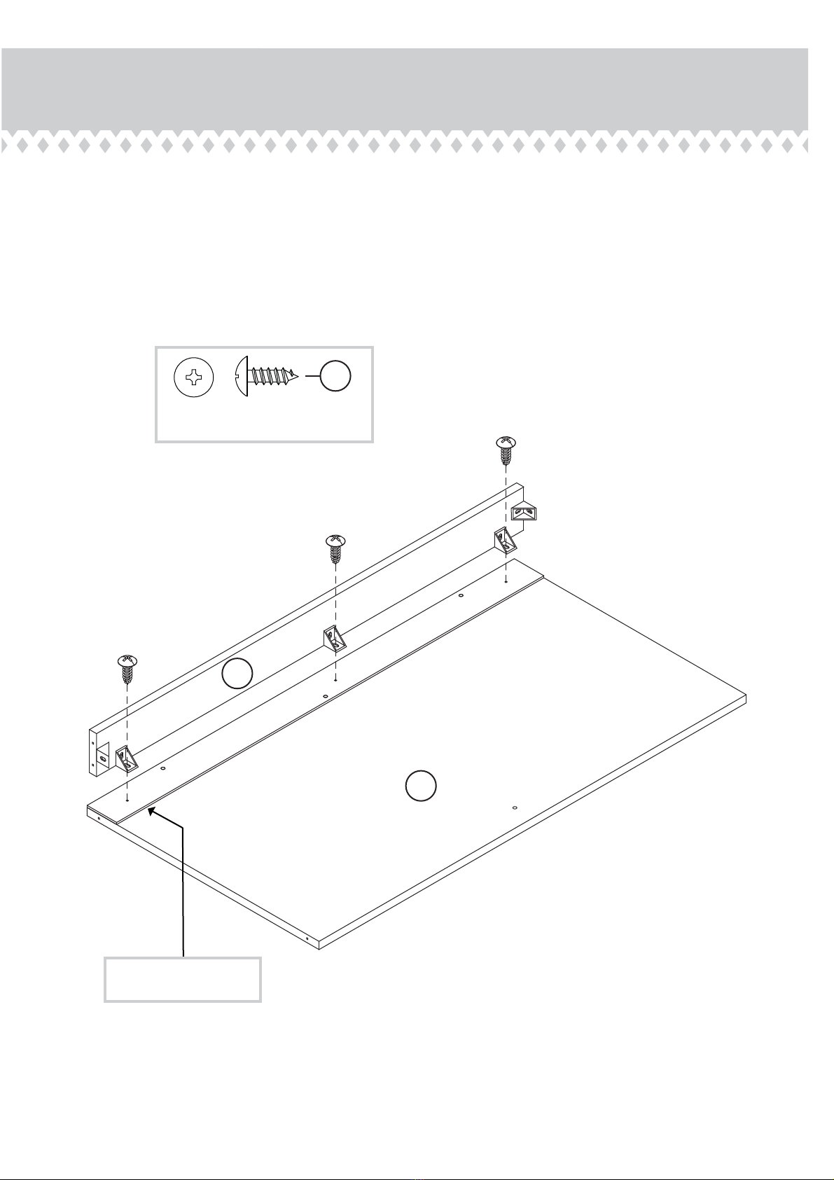
å Fasten the VALANCES (K) to the TOP (D). Use eight 1-1/2"
FLAT HEAD SCREWS (13).
Step 3
D
K
Some assembly
(and snacks) required.
Page 7
www.sauder.com422784
1-1/2" FLAT HEAD SCREW
(8 used in this step)
13
Finished surface
K
D
Unfinished surface
1st
2nd
This arrow should
be pointing up.
This arrow should
be pointing down.
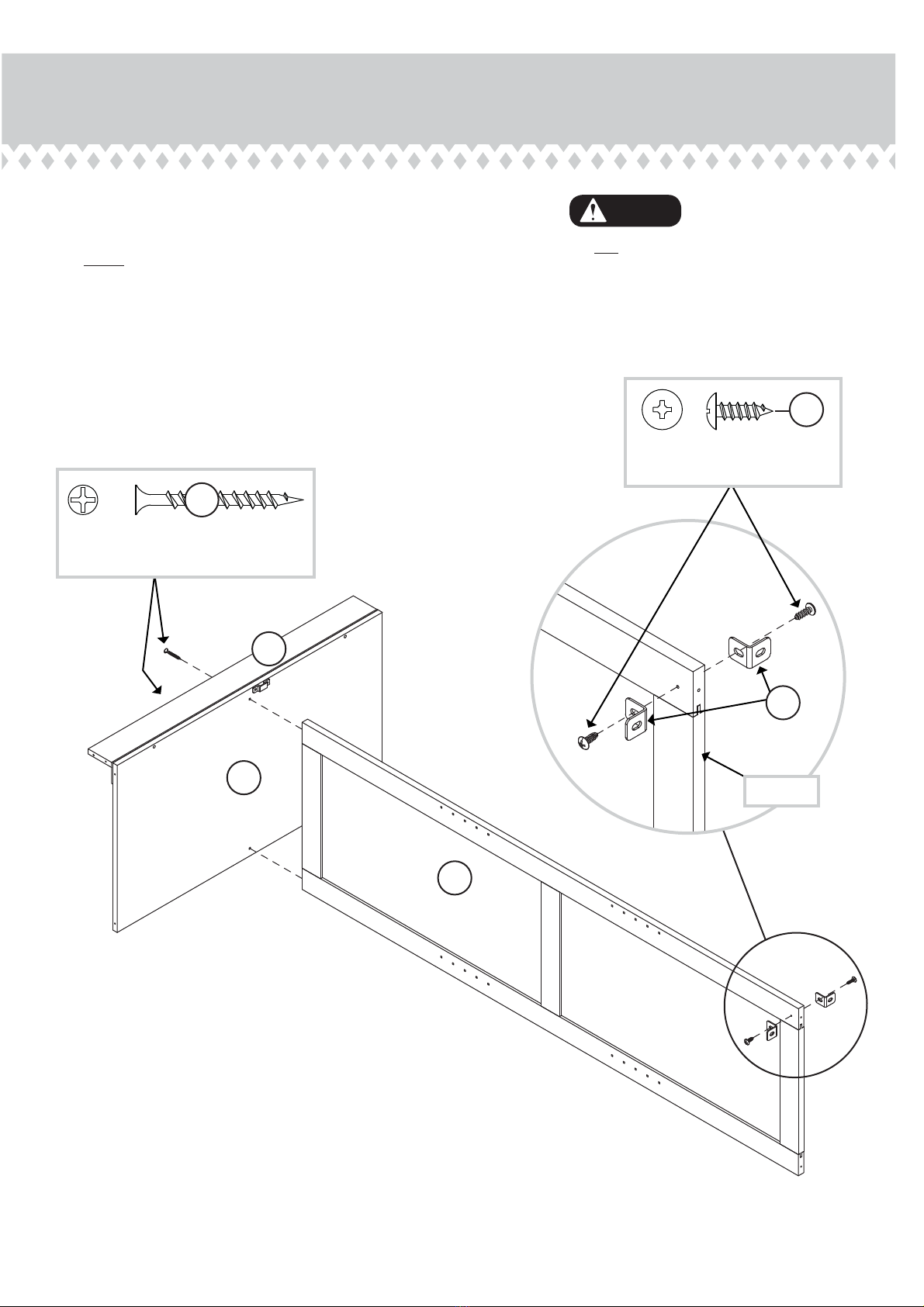
Step 4
å Fasten two METAL BRACKETS (8) to the UPRIGHT (C).
Use two 1/2" PAN HEAD SCREWS (18).
å NOTE: Be sure the edges of the METAL BRACKETS are
even with the top edge of the UPRIGHT.
å Fasten the BOTTOM (E) to the UPRIGHT (C). Use two
1-1/2" FLAT HEAD SCREWS (13).
E
L
C
1-1/2" FLAT HEAD SCREW
(2 used in this step)
13
8
1/2" PAN HEAD SCREW
(2 used in this step)
18
Do not stand the unit upright without the
BACK fastened. The unit may collapse.
Caution
Page 8 www.sauder.com 422784
Top edge

å Finish fastening the BOTTOM (E) to the SKIRT (L). Use
two 1-1/2" FLAT HEAD SCREWS (13).
å Fasten the SHELF (F) to the UPRIGHT (C). Use two 1-1/2"
FLAT HEAD SCREWS (13)
å Finish fastening the SHELF (F) to the UPRIGHT (C). Use
two 1/2" PAN HEAD SCREW S (18) through the METAL
BRACKETS on the UPRIGHT and into the SHELF.
å Then, peel four APPLIQUES (7) from the applique card
and stick them over the heads of the SCREWS (13).
Step 5
E
C
F
Peel the APPLIQUES
from the applique card.
7
L
1-1/2" FLAT HEAD SCREW
(4 used in this step)
13
7
The molding on the
SHELF should be here.
Page 9
www.sauder.com422784
1/2" PAN HEAD SCREW
(2 used in this step)
18
7
å Fasten the HINGE BRACKETS (3) to the ENDS (A and B).
Use the SCREWS in the HINGE BRACKETS.
å NOTE: The arrow on the HINGES should face towards the
edge of the ENDS.
Step 6
B
A
3
3
Page 10 www.sauder.com 422784
3

Step 7
E
F
K
L
D
Edge with
HINGE BRACKETS
B
Hey! It's starting to look
like something!
1-1/2" FLAT HEAD SCREW
(13 used in this step)
13
Page 11
www.sauder.com422784
K
Finished surface
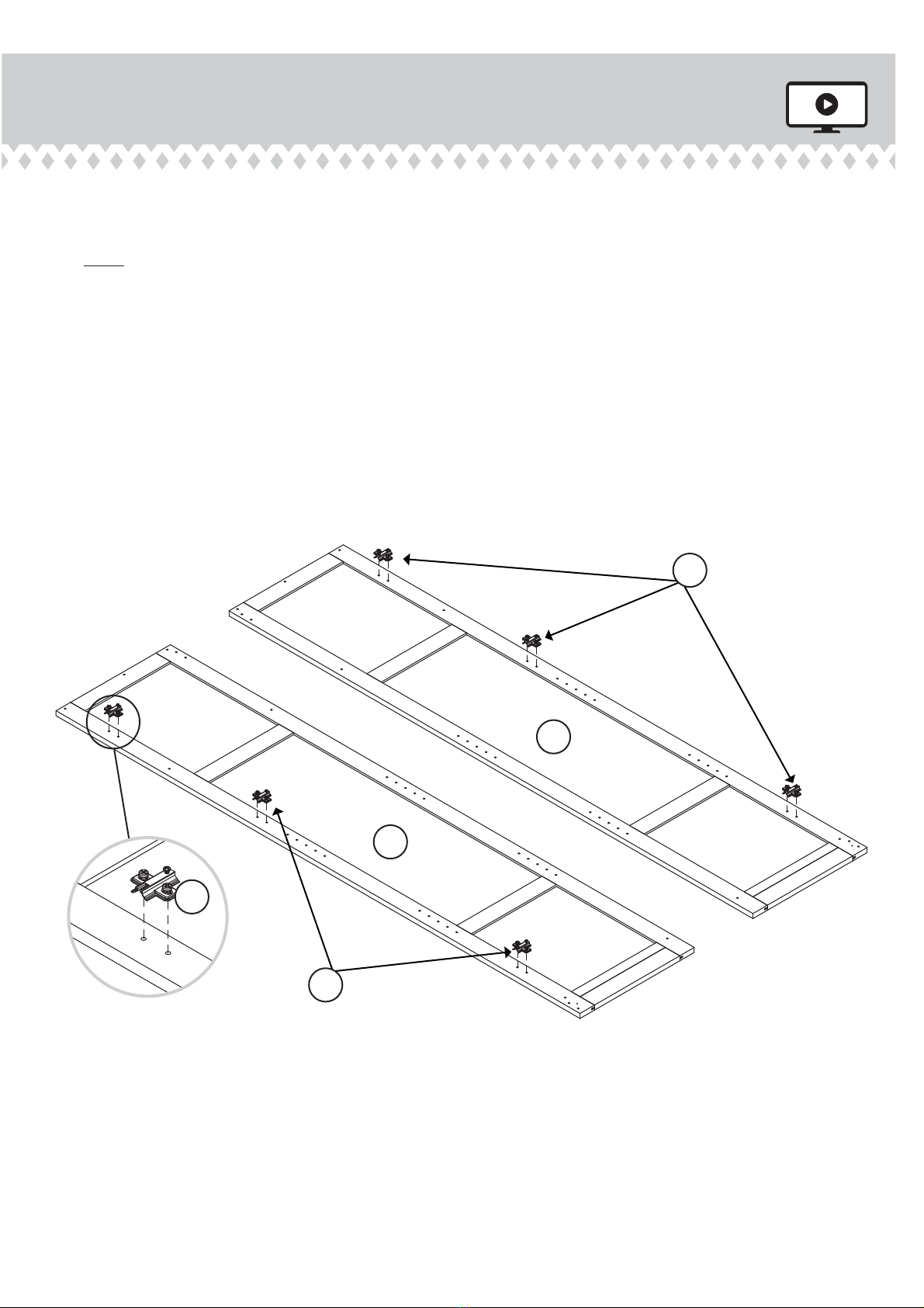
å Fasten the LEFT END (B) to the TOP (D), BOTTOM (E),
SHELF (F), VALANCES (K), and SKIRT (L). Use thirteen
1-1/2" FLAT HEAD SCREWS (13).
å Finish fastening the LEFT END (B) to the SKIRT (L). Use a
LARGE 1/2" PAN HEAD SCREW (19) through the ANGLE
BRACKET on the SKIRT and into the LEFT END.
LARGE 1/2" PAN HEAD SCREW
(1 used for the ANGLE BRACKET)
19

Step 8
E
L
F
D
A
Edge with
HINGE BRACKETS
1-1/2" FLAT HEAD SCREW
(13 used in this step)
13
Page 12 www.sauder.com 422784
K
K
å Fasten the RIGHT END (A) to the TOP (D), BOTTOM (E),
SHELF (F), VALANCES (K), and SKIRT (L). Use thirteen
1-1/2" FLAT HEAD SCREWS (13).
å Finish fastening the RIGHT END (A) to the SKIRT (L).
Use a LARGE 1/2" PAN HEAD SCREW (19) through the
ANGLE BRACKET on the SKIRT and into the RIGHT END.
LARGE 1/2" PAN HEAD SCREW
(1 used for the ANGLE BRACKET)
19

Step 9
å Carefully turn your unit over onto its front edges. Unfold
the BACK (G2) and lay it over your unit.
å Make equal margins along all four edges of the BACK (G2).
Push on opposite corners of your unit if needed to make
it "square".
å Using your hammer, fasten the BACK (G2) to your unit
using the NAILS (12).
å NOTE: Be sure to tap NAILS into the holes that line up
over the UPRIGHT (C).
å Peel the backing o of each FELT DISC (20) and stick
them on the edge of the ENDS (A and B).
å NOTE: Be sure the FELT DISCS are placed approximately
1/8" in from the front edge of the ENDS.
Do not stand the unit upright without the
BACK fastened. The unit may collapse.
Caution
NAIL
(36 used in this step)
12
Page 13
www.sauder.com422784
G2
Unfinished
surface
These holes must line up
over the UPRIGHT (C).
A
B
20
This FELT DISC should set in 1/8"
from the front edge of the ENDS.
This FELT DISC should set in 1/8"
from the front edge of the ENDS.
The large hole
should be here.

å Fasten the HINGES (2) to the DOORS (H and I). Use
twelve 1/2" FLAT HEAD SCREWS (17).
å Fasten the DOOR BRACKET (10) to the LEFT DOOR (I).
Use two 1/2" PAN HEAD SCREWS (18).
Step 10
H
I
2
2
2
1/2" FLAT HEAD SCREW
(12 used for the HINGES)
17
10
1/2" PAN HEAD SCREW
(2 used for the DOOR BRACKET)
18
Page 14 www.sauder.com 422784
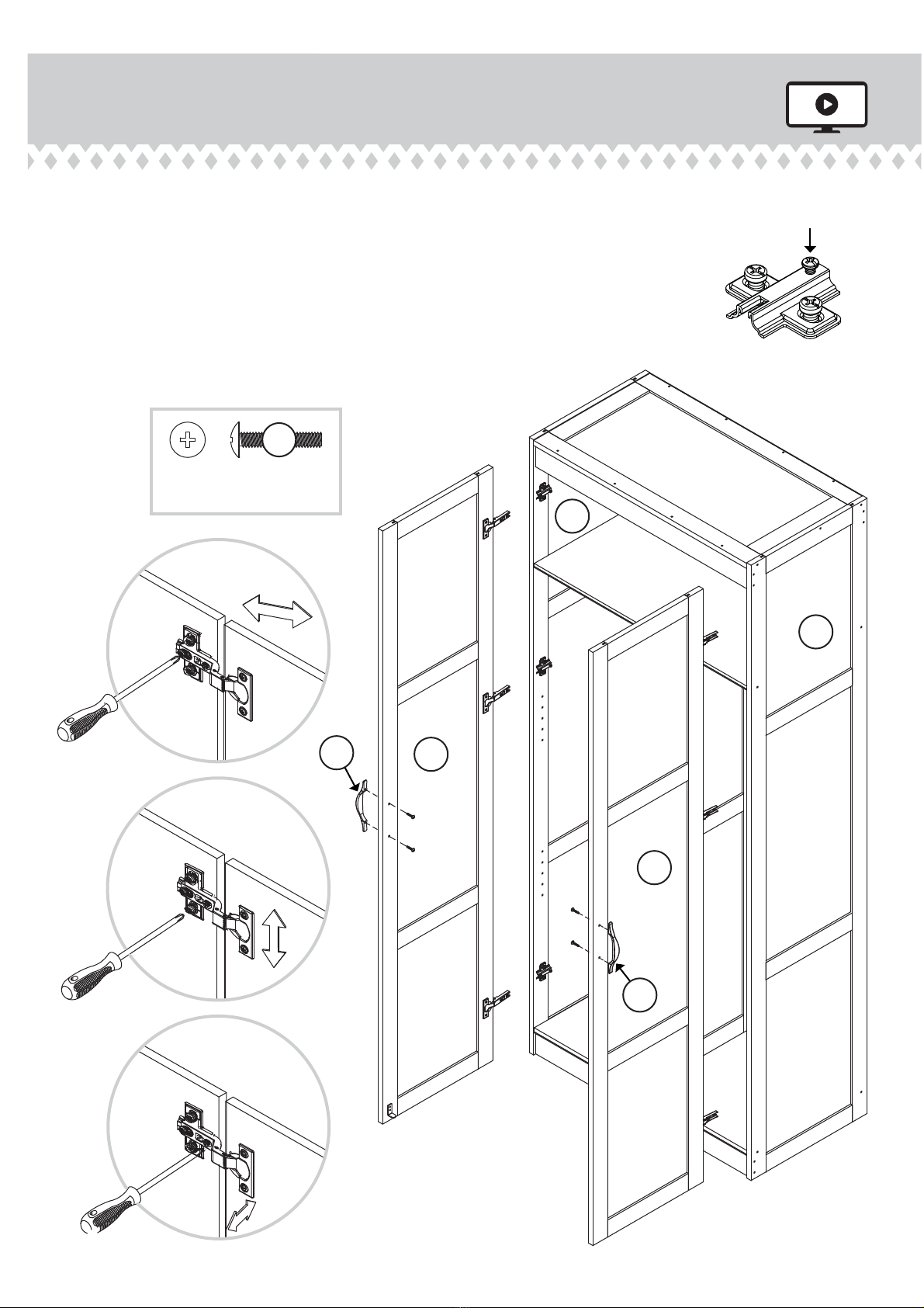
å Carefully stand your unit upright.
å Fasten the DOORS (H and I) to the ENDS (A and B). Slide the HINGES
on the DOORS onto the HINGE BRACKETS on the ENDS. Secure the
DOORS with the mounting screw on the HINGE BRACKET.
å See the enlarged diagrams for adjustments.
å Fasten the PULLS (4) to the DOORS (H and I). Use four 3/4"
MACHINE SCREWS (15).
Step 11
H
I
A
B
Mounting
screw
HINGE BRACKET
3/4" MACHINE SCREW
(4 used for the PULLS)
15
4
4
Page 15
www.sauder.com422784
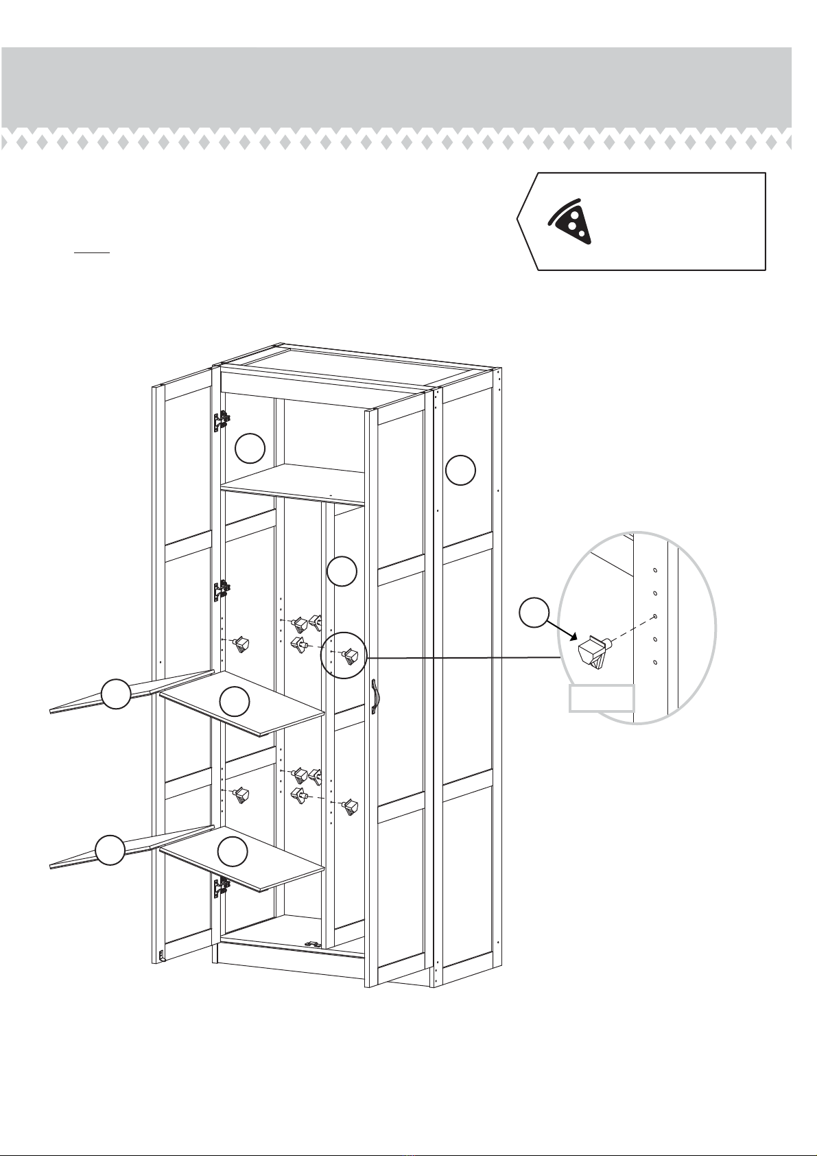
Step 12
å Insert the SHELF SUPPORTS (11) into the hole locations of
your choice in the ENDS (A and B) and UPRIGHT (C). Set the
ADJUSTABLE SHELVES (J) onto the SHELF SUPPORTS.
å NOTE: The lips of the ADJUSTABLE SHELVES can face
either up or down in your unit.
A
B
C
J
J
J
J
If you're doing this to
help a friend, don't
leave without a bite.
(16 used)
11
Page 16 www.sauder.com 422784
Step 13
Page 17
www.sauder.com422784
å We recommend using the FURNITURE TIPPING RESTRAINT KIT (99) for added stability. Fasten a bracket to the back
edge of the TOP (D) using the 5/8" screw as shown.
å Place your unit in its final location against a wall.
å Follow the instructions included in the KIT to fasten your unit to the wall.
99
Use the 5/8" screw through the
small hole in a bracket and into
the back edge of the TOP (D).
Small hole
D
Step 14
Page 18 www.sauder.com 422784
å Peel twenty-six APPLIQUES (7) from the applique card and stick them over the heads of the
SCREWS in the ENDS (A and B).
å NOTE: Please read the back pages of the instruction booklet for important safety information.
å This completes assembly. Clean with your favorite furniture polish or a damp cloth. Wipe dry.
No load
Weight Limits:
Top Shelf - 50 lbs.
Adjustable Shelf - 25 lbs. each
Bottom - 50 lbs. total
Peel the APPLIQUES
from the applique card.
A
B
(26 used)
And to celebrate, why not share your success story?
7

A l’usage exclusif du
Canada Noter la date
d’achat de cet élément
et conserver le livret
pour future référence.
Pour contacter Sauder
en ce qui concerne cet
élément, faire référence
au numéro de lot et
numéro de modèle en
appelant notre numéro
sans frais.
Lot nº : ____________
Date de
l’achat: ____________
LISTE DE PIÈCES
REFERENCE DESCRIPTION QUANTITÉ
LISTE DE PIÈCES
REFERENCE DESCRIPTION QUANTITÉ
NOUS SOMMES LA POUR VOUS AIDER!
Nous faisons de notre mieux pour nous assurer que votre meuble
arrive dans d’excellentes conditions. Nos représentants du service
Clientèle sont aimables et prêts à vous aider au cas où une pièce
aurait été endommagée ou manquerait (ou si vous aviez besoin
d’aide pour l’assemblage). NE RAMENEZ PAS LE MEUBLE AU
MAGASIN. Au Canada, composez ce numéro d’appel gratuit:
1-800-445-1527
Du lundi au vendredi, de 9 heures du matin à
5:30 heures du soir (horaire Côte Est)
(sauf jours fériés)
Si une pièce a besoin d’être remplacée, la pièce de remplacement
sera envoyée dans les 48 heures. (Sauf week-ends et jours fériés)
Utilisez les instructions d’assemblage en français avec les
schémas étape par étape du manuel d’instruction en anglais.
Chaque étape en français correspond à la même étape
en anglais. La pièce devant être attachée à l’élément est
représentée en gris sur les schémas de chaque étape pour plus
de précision. Comparer la “Liste de pièces” ci-dessous avec
la “PART IDENTIFICATION” du manuel en anglais pour vous
familiariser avec les pièces avant l’assemblage.
REMARQUE : CE MANUEL D’INSTRUCTIONS CONTIENT
D’IMPORTANTES INFORMATIONS RELATIVES À LA SÉCURITÉ.
À LIRE ET CONSERVER POUR TOUTE RÉFÉRENCE FUTURE.
1 CONSOLE À ÉQUERRE.........................................5
2 CHARNIÈRE.....................................................................6
3 CONSOLE DE CHARNIÈRE.................................6
4 POIGNÉE............................................................................2
7 AUTO-COLLANT ....................................................30
8 CONSOLE EN MÉTAL.............................................2
9 CONSOLE DE DESSOUS.................................... 1
10 CONSOLE DE PORTE............................................ 1
11 SUPPORT DE TABLETTE...................................16
12 CLOU ................................................................................36
20 TAMPON EN FEUTRE..............................................4
13 VIS TÊTE PLATE 38 mm...................................40
15 VIS À MÉTAUX 19 mm............................................4
17 VIS TÊTE PLATE 13 mm......................................12
18 VIS TÊTE GOUTTE DE SUIF 13 mm............8
19 GRAND VIS TÊTE GOUTTE
DE SUIF 13 mm.........................................................10
99 KIT DE RETENUE ANTI-BASCULEMENT
POUR MOBILIER...........................................................1
A EXTRÉMITÉ DROITE..................................................1
B EXTRÉMITÉ GAUCHE...............................................1
C MONTANT ........................................................................1
D DESSUS...............................................................................1
E DESSOUS...........................................................................1
F TABLETTE..........................................................................1
G2 ARRIÈRE ..............................................................................1
H PORTE DROITE .............................................................1
I PORTE GAUCHE..........................................................1
J TABLETTE RÉGLABLE............................................4
K LAMBREQUIN................................................................2
L PLINTHE..............................................................................1
Meuble de rangementModèle 422784
Page 19
www.sauder.com422784
DESIGNER’S IMAGE®

ÉTAPE 6
Fixer les CONSOLES DE CHARNIÈRE (3) aux EXTRÉMITÉS (A
et B). Utiliser les VIS dans les CONSOLES DE CHARNIÈRE.
REMARQUE : La flèche sur les CHARNIÈRES doit être dirigée
vers le chant des EXTRÉMITÉS.
ÉTAPE 5
Finir de fixer le DESSOUS (E) à la PLINTHE (L). Utiliser deux VIS
TÊTE PLATE 38 mm (13).
Fixer la TABLETTE (F) au MONTANT (C). Utiliser deux VIS TÊTE
PLATE 38 mm (13).
Finir de fixer la TABLETTE (F) au MONTANT (C). Utiliser deux VIS
TÊTE GOUTTE DE SUIF 13 mm (18) à travers les CONSOLES EN
MÉTAL sur le MONTANT et dans la TABLETTE.
Ensuite, décoller quatre AUTO-COLLANTS (7) de la fiche d'auto-
collants et les coller sur les têtes des VIS (13).
ÉTAPE 4
Attention: Ne pas relever l'élément dans sa position verticale
avant d'avoir fixé l’ARRIÈRE. L'élément risque de s'eondrer.
Fixer deux CONSOLES EN MÉTAL (8) au MONTANT (C). Utiliser
deux VIS TÊTE GOUTTE DE SUIF 13 mm (18).
REMARQUE : S'assurer que les chants des CONSOLES EN
MÉTAL sont à fleur des chants du MONTANT.
Fixer le DESSOUS (E) au MONTANT (C). Utiliser deux VIS
TÊTE PLATE 38 mm (13).
ÉTAPE 3
Fixer les LAMBREQUINS (K) au DESSUS (D). Utiliser huit VIS
TÊTE PLATE 38 mm (13).
ÉTAPE 2
Fixer la PLINTHE (L) au DESSOUS (E). Utiliser trois GRAND VIS
TÊTE GOUTTE DE SUIF 13 mm (19) à travers les CONSOLES À
ÉQUERRE sur le LAMBREQUIN et dans le DESSOUS.
ÉTAPE 1
Assembler l'élément sur un sol à moquette ou sur le carton vide
pour éviter d'endommager l'élément ou le sol.
Fixer cinq CONSOLES À ÉQUERRE (1) à la PLINTHE (L). Utiliser
cinq GRAND VIS TÊTE GOUTTE DE SUIF 13 mm (19).
REMARQUE : S'assurer que les chants des CONSOLES À
ÉQUERRE sont à fleur des chants de la PLINTHE.
Fixer la CONSOLE DE DESSOUS (9) au DESSOUS (E). Utiliser
deux VIS TÊTE GOUTTE DE SUIF 13 mm (18).
Page 20 www.sauder.com 422784
ÉTAPE 8
Fixer l'EXTRÉMITÉ DROITE (A) au DESSUS (D), au DESSOUS (E),
à la TABLETTE (F), aux LAMBREQUINS (K) et au PLINTHE (L).
Utiliser treize VIS TÊTE PLATE 38 mm (13).
Finir de fixer l'EXTRÉMITÉ DROITE (A) à la PLINTHE (L). Utiliser
une GRAND VIS TÊTE GOUTTE DE SUIF 13 mm (19) à travers la
CONSOLE À ÉQUERRE sur la PLINTHE et dans l'EXTRÉMITÉ DROITE.
ÉTAPE 7
Fixer l'EXTRÉMITÉ GAUCHE (B) au DESSUS (D), au DESSOUS (E),
à la TABLETTE (F), aux LAMBREQUINS (K) et au PLINTHE (L).
Utiliser treize VIS TÊTE PLATE 38 mm (13).
Finir de fixer l'EXTRÉMITÉ GAUCHE (B) à la PLINTHE (L). Utiliser une
GRAND VIS TÊTE GOUTTE DE SUIF 13 mm (19) à travers la CONSOLE
À ÉQUERRE sur la PLINTHE et dans l'EXTRÉMITÉ GAUCHE.
Other designer's image Indoor Furnishing manuals

designer's image
designer's image 422705 User manual

designer's image
designer's image WIL-1636-5B User manual

designer's image
designer's image 211-4513 User manual

designer's image
designer's image 211-4525 User manual

designer's image
designer's image 211-4578 User manual

designer's image
designer's image 211-4581 User manual

designer's image
designer's image 211-4598 User manual

designer's image
designer's image 211-4519 User manual

designer's image
designer's image 211-4569 User manual


