DESKHAUS APEX PROMAX/6 User manual

APEX PROMAX/6
APEX
PROMAX/6
PRODUCT ASSEMBLY INSTRUCTIONS

APEX PROMAX/6
NOTES
Read all instructions and review all illustrations before installing. Failure to observe these
warnings could result in a fire or electrical shock. Use two or more people when moving
products or personal injury may result. Ensure there are no obstacles in unit's path and that
it is clear of walls during movement. Cords must be appropriate length to accommodate
change in height. Keep children away from height adjustable base. Keep electrical components
away from liquids. Do not sit or stand on base or work surface. Do not open any components.
Designed for a 10% duty cycle, two minutes on and eighteen minutes off. In the event of a
power outage, or if the power cord is unplugged, a reset is required.
WARNING
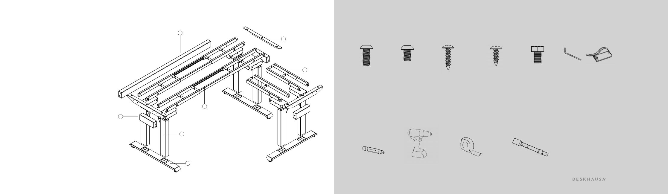
PARTS QTY
1. Column 6
2. Top Supports 3
3. Foot 3
4. Collapsing Channel 2
5. Fixed Channel 2
6. Short Cross Bar 3
7. Long Cross Bar 1
Jumper 1
Control Box 2
Hand Switch 1
Power Cord 2
M6 14mm Screw 36
M6 10mm Screw 40
7/8" Wood Screw 23
16mm Wood Screw 2
Feet Pads 6
Cable Ties 20
Cable Extensions 4
APEX PROMAX/6
1
2
3
4
APEX PROMAX/6
TOOLS NEEDED:
PARTS INCLUDED:
X40
X36 X23 X2
4mm HEX KEY
X20
M6 14mm M6 10mm 7/8 WOOD SCREW 16mm WOOD SCREW CABLE TIES
X6
M8 12mm
13mm SOCKET HEAD + EXTENSION
6
7
5
TAPE MEASURE
CORDLESS DRIVERPHILLIPS BIT

APEX PROMAX/6
*Please note orientation of all screw holes
making sure channels are not upside down.
ASSEMBLE COLUMNS TO
COLLAPSING CHANNELS
Assemble using the M6 10mm length screws.
These are the shorter screws that are included.
(4 per column)
Notes
*You need to separate the channels and attach each of the 4 columns individually
1
IMPORTANT: Do not tighten machine screws fully until the end of each step to allow for proper centering. PARTS QTY
Column 6
Collapsing Channel 2
Fixed Channel 2
M6 10mm Screw 24
X24
X3

APEX PROMAX/6
X12
IMPORTANT: Do not tighten machine screws fully until the end of each step to allow for proper centering. PARTS QTY
Short Cross Bar 3
M8 12mm Screw 6
ASSEMBLE SHORT CROSS BARS
BETWEEN COLUMNS
Assemble using the M8 12mm length screws.
(2 per side)
*Note- You will need a socket extension to reach the bolts inside the cross bar
2
Table of contents
Other DESKHAUS Indoor Furnishing manuals


Popular Indoor Furnishing manuals by other brands

Regency
Regency LWMS3015 Assembly instructions

Furniture of America
Furniture of America CM7751C Assembly instructions

Safavieh Furniture
Safavieh Furniture Estella CNS5731 manual

PLACES OF STYLE
PLACES OF STYLE Ovalfuss Assembly instruction

Trasman
Trasman 1138 Bo1 Assembly manual

Costway
Costway JV10856 manual


