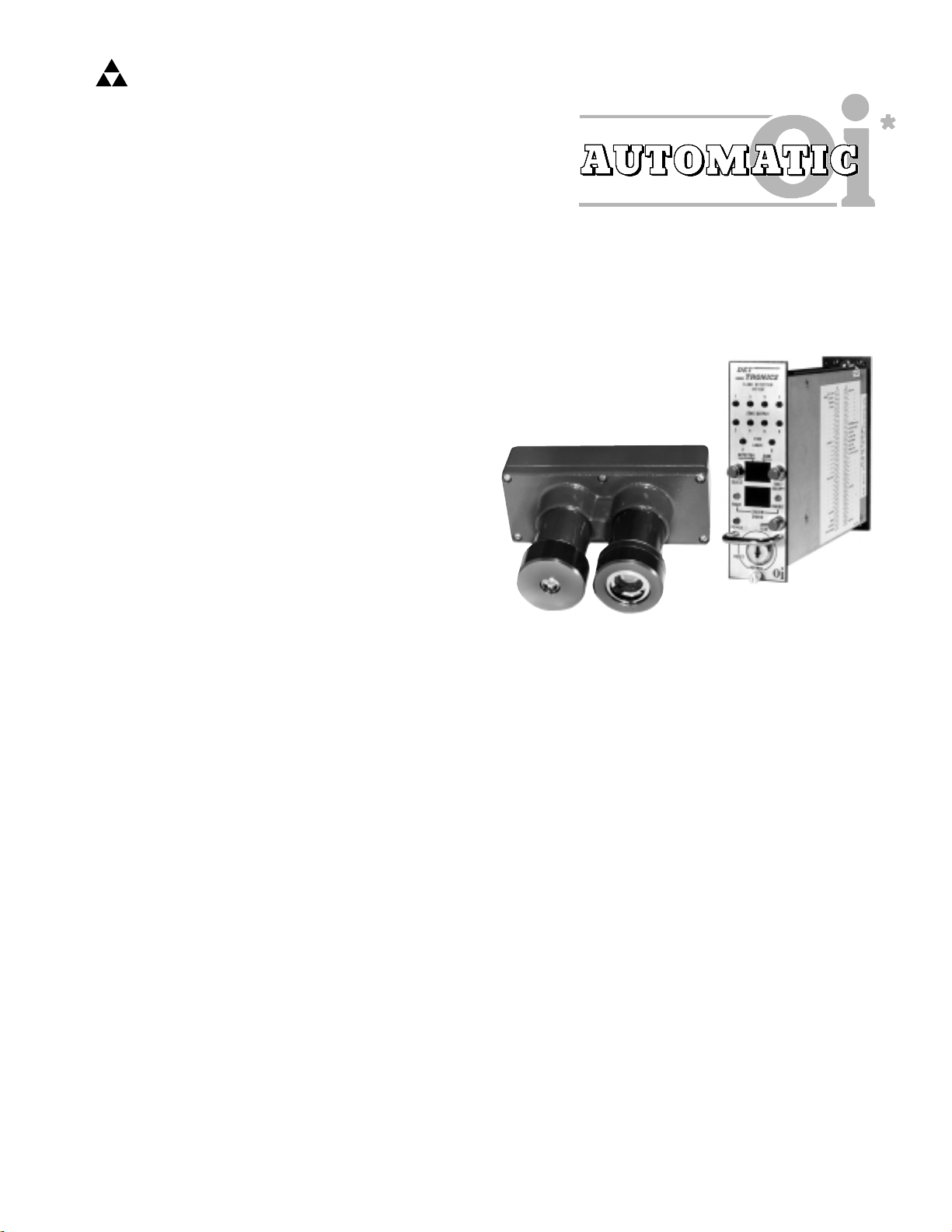
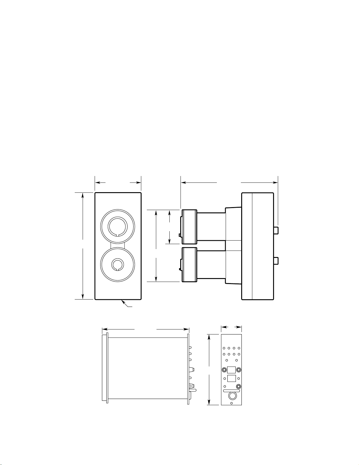
1. A ZONE OUTPUT LED is provided for each
detector to indicate that a fire has been detected.
The LEDs blink while the zone output is active and
latch on when the fire is no longer detected and the
output turns off.
2. The FIRE LOGIC LEDs signal actuation of the cor-
responding Logic outputs.
3. The DETECTOR - ZONE digital display indicates
the detector zone number that first responded to
a fire, detector(s) indicating a fault, detector zone
selected manually in the keylock switch Test
mode, or the counts per second reading from the
detector zone in the Count Test mode.
4. The SYSTEM STATUS display uses a numerical
code to identify system status (see Table 1).
5. Illumination of the FAULT LED indicates a system
malfunction (or that the controller is in the Reset
or Test mode).
6. The INHIBIT LED is energized in the Test or Reset
mode to show that the outputs of the controller
are inhibited.
7. The POWER LED is illuminated when power is
applied to the system.
8. The SELECT button is pressed to choose a detec-
tor for test.
9. In the Test mode the TEST/ACCEPT button initi-
ates a manual oitest for the selected detector.
In the Normal mode, the TEST/ACCEPT button is
used to disable the alarm output when a fire
occurs without affecting the Zone or Fire Logic
outputs.
10. The LAMP TEST button illuminates all LEDs and
all segments of the displays. In the Reset mode,
it initiates a complete microprocessor reset.
11. The keylock switch selects NORMAL, RESET or
TEST mode.
Normal Mode
In the Normal operating mode, the R7494 Controller
monitors the outputs of all detectors connected to it
and compares the detector output signals to field
adjusted settings (refer to the “STAR Logic
Programming” procedure in the “Programming the
Controller” section) to determine whether a fire condi-
tion exists. Diagnostic circuitry continuously checks
the system for wiring continuity as well as faults that
could prevent proper response to a fire through the
Automatic oifeature. The Zone, Fire Logic and Fire
Alarm outputs are de-energized. The Fault output is
energized, as long as no system malfunctions are
detected. None of the LEDs except the POWER LED
are illuminated and the digital displays are blank.
Reset Mode
Any existing system status indications and the con-
troller outputs are returned to normal operating condi-
tion (after the radiation source is removed or the fault
is corrected) in one of the following ways:
1. Place the keylock switch in the RESET position,
then return it to NORMAL.
2. Close the optional remote reset switch connected
to controller terminal 44 and circuit ground (termi-
nal 2).
Test Mode
In the Normal mode, the Automatic oifeature continu-
ously checks the detectors for proper operation.
Additional manual oitesting capabilities are provided
by using the controller Test mode. Among the possi-
ble tests are:
1. A Manual oitest, which individually tests the
selected detector and its electronic circuitry.
2. A Count Test mode, which displays the output fre-
quency of an individual detector using the
DETECTOR and ZONE displays.
3. A Bus Test mode, which tests the data bus wiring
and indicates results on the front panel of the
controller when intercontroller voting is used.
These test features enable the user to more easily
pinpoint a system malfunction. Refer to the
“Troubleshooting” section.
PROGRAMMING SWITCHES
Rocker switches that are located on the side of the
controller are used for selecting various options avail-
able with the R7494. These programming options are
listed below and must be set prior to system opera-
tion. Refer to the “Programming the Controller” sec-
tion for detailed instructions.
1. Number of detectors connected to the controller
(up to eight)
2. Gate Length, Consecutive Gate Selection, Count
Selection (system sensitivity and time delay).
3. Fire Logic (voting arrangement)
4. Latching/non-latching outputs.
5. Intercontroller voting.
4