and/or instructions for calibration. When a display is not
used or the LED is not visible from the outside, the
enclosure must be opened to observe the LED or to
insert a meter to read the output of the device (intrusive
calibration). With this type of installation, either a permit
must be obtained to open the enclosure or the proce-
dure must be accomplished by two people using walkie
talkies for communication.
Depending on the control devices selected, PointWatch
can be installed for either intrusive or non-intrusive cali-
bration. See Table 3 for a listing of the installation
options.
A user-supplied junction box can also be used, provid-
ed it has the appropriate sized entries. This junction
box must be suitable for use in the application and loca-
tion in which it is being installed. Calibration is initiated
by touching the calibration lead to the negative lead
(common) of the power supply. Although this can be
accomplished manually, installation of a switch is rec-
ommended. It is recommended that this switch be a
momentary contact type to prevent it from inadvertently
being left in the calibrate position.
GENERAL WIRING REQUIREMENTS
NOTE
The wiring procedures in this manual are intended
to ensure proper functioning of the device under
normal conditions. However, because of the many
variations in wiring codes and regulations, total
compliance to these ordinances cannot be guaran-
teed. Be certain that all wiring complies with appli-
cable regulations relating to the installation of elec-
trical equipment in a hazardous area. If in doubt,
consult the authority having jurisdiction before
wiring the system.
The use of shielded cable in conduit or shielded
armored cable is recommended for optimum RFI/EMI
protection. In applications where the wiring cable is
installed in conduit, the conduit must not be used for
wiring to other electrical equipment. To assure proper
operation of the detector, the resistance of the connect-
ing wire must be within the specified limits. The maxi-
mum distance between the detector and power source
is determined by the power supply capability and wire
size. See Figure 2 to determine the proper wire size
and maximum wiring distance allowed.
It is important that moisture not be allowed to come in
contact with the electrical connections of the system.
The use of proper piping techniques, breathers, glands,
and seals are required to prevent water ingress and/or
maintain the explosion-proof rating.
DETECTOR WIRING PROCEDURE
IMPORTANT
Do not apply power until the wiring procedure is
complete and has been verified.
1. Determine the best mounting location for the detec-
tor (refer to the “Detector Location” section above).
If it is determined that sensor separation is required,
see the following section for details.
2. The junction box should be electrically connected
to earth ground.
3. Figures 14 through 18 show typical wiring for vari-
ous system configurations using the PointWatch
detector. Refer to the appropriate figure as a guide
to system connection. Figure 14 shows typical
wiring for standalone operation. Figure 15 shows
typical wiring for PointWatch with Det-Tronics sup-
plied junction box. Figure 16 shows the junction box
terminals and calibration switch. Figure 17 shows
typical wiring for PointWatch/Infiniti transmitter oper-
ation. Figure 18 shows typical wiring for
PointWatch/Eagle communication module configura-
tion. The PointWatch wiring color code is:
Red lead = +24 volts dc
Black lead = – (common)
White lead = 4 to 20 ma signal output
Yellow lead* = Calibration input
Green lead = Chassis ground
*If the calibration wire (yellow lead) is not
being used, do not connect this wire to
ground. Trim excess length and insulate
wire so no shorting can occur.
4. Check the detector wiring to ensure proper connec-
tions, then pour the conduit seals and allow them to
dry (if conduit is being used).
DETECTOR SEPARATION (OPTIONAL)
In applications where the detector must be installed in a
different location from the control device, a junction box
must be installed at the detector location to make the
8
Table 3—
Installation Options for Intrusive and Non-Intrusive Calibration
Control Device Non-Intrusive Intrusive or
& 1 person 2 person
Infiniti Transmitter X
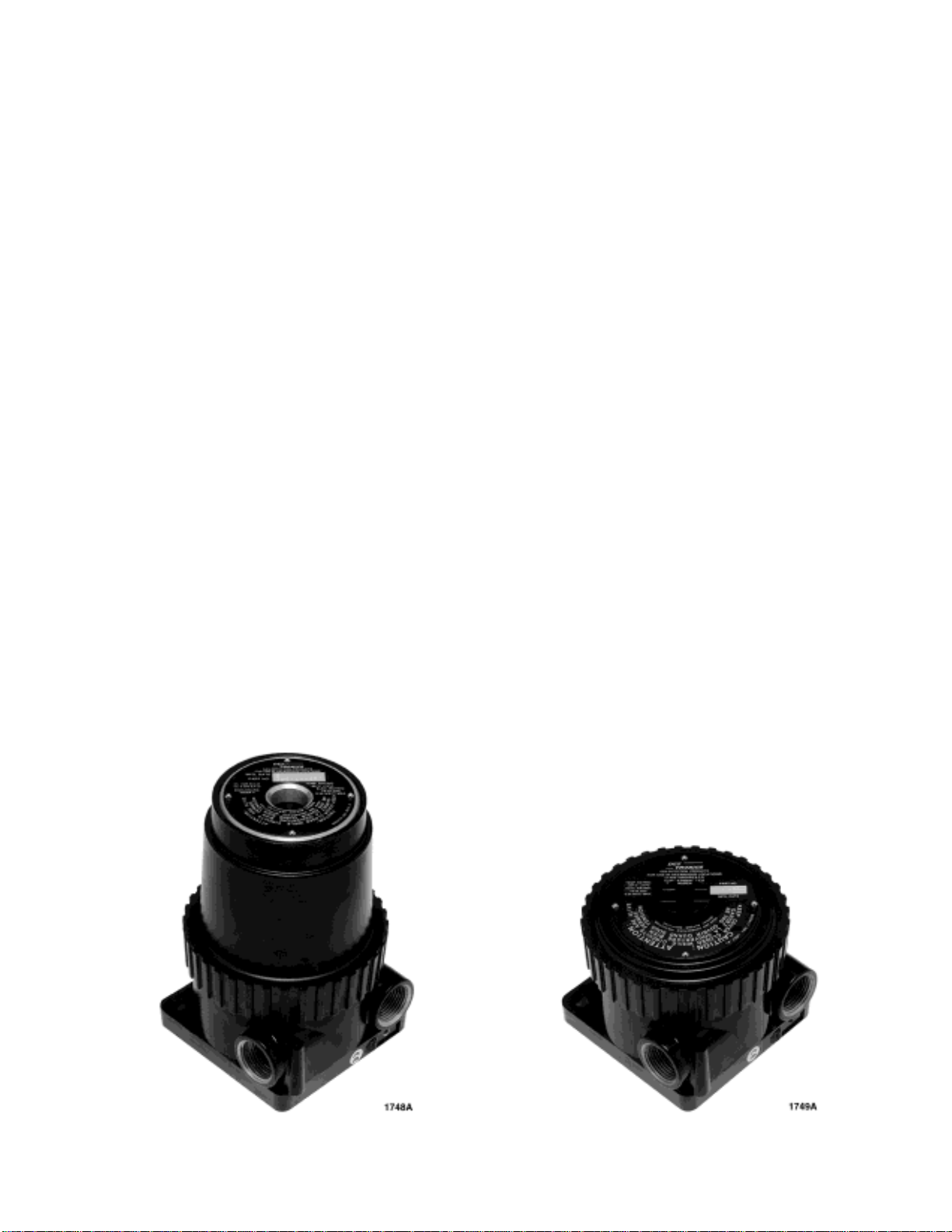
PointWatch Junction Box X
w/ tall cover/window
PointWatch Junction Box X
w/ short cover/no window
Eagle 2000 DCU X
Eagle 2000 Communication Module X