Det-Tronics 95-8632 User manual

Instructions 95-8632
Volumetric Infrared Hydrocarbon Gas Process Monitor
for Heavy Hydrocarbons
PIRVOLHV
3.1 Rev: 1/12 95-8632

Table Of Contents
APPLICATION .............................................1
FEATURES ...............................................1
SPECIFICATIONS ..........................................1
DESCRIPTION ............................................4
Detection Method .......................................4
Current Loop Output .....................................4
Signal Display Device ....................................4
Operating Modes .......................................4
INSTALLATION ............................................5
Device Mounting Orientation ..............................5
Termination Boxes (PIRTB)................................5
General Wiring Requirements .............................5
Wiring Procedure .......................................6
Detector Separation (Optional) .............................7
STARTUP PROCEDURE ....................................8
TROUBLESHOOTING ......................................8
MAINTENANCE ...........................................8
Disassembly and Cleaning Procedure .......................9
Calibration............................................10
REPLACEMENT PARTS ....................................11
DEVICE REPAIR AND RETURN .............................11
ORDERING INFORMATION .................................12
APPENDIX A – CSA APPROVAL .............................13
APPENDIX B – ATEX / CE APPROVAL ........................14
APPENDIX C – IECEx APPROVAL............................15

INSTRUCTIONS
Volumetric Infrared Hydrocarbon
Gas Process Monitor
for Heavy Hydrocarbons
PIRVOLHV
APPLICATION
PIRVOLHV is a point-type infrared hydrocarbon
gas process monitor. It provides a continuous 4-20
milliampere (mA) output signal that is proportional to
propane vapor concentrations from 0 to 100% by volume.
PIRVOLHV is designed for use in extractive vapor
sampling systems where the vapor concentration is likely
to be above the lower flammability limit (LFL). Typical
applications for the PIRVOLHV include hydrocarbon well
logging and petroleum exploration where a volumetric
measurement of the target gas is required.
PIRVOLHV is furnished with a sealed aluminum or stainless
steel vapor sampling enclosure. Brass compression-
type tubing fittings on the enclosure (for use with 0.25
inch o.d. tubing) allow easy connection to the inlet and
exhaust lines of the vapor sample extraction system.
PIRVOLHV is CSA certified for use in Class I, Division 1,
Groups B, C and D; and Class I, Division 2, Groups A, B,
C and D areas.
FEATURES
• Routine calibration not required.
• Continuous self-test automatically indicates a fault or
fouled optics condition.
• Performs well in the presence of high concentrations
or constant background levels of hydrocarbons and
in oxygen depleted atmospheres.
• There are no known poisons, e.g. silicones or
hydrides, that compromise the integrity of the
measurement.
SPECIFICATIONS
INPUT VOLTAGE—
24 Vdc nominal. Operating range is 18 to 32 Vdc including
ripple.
POWER CONSUMPTION (WATTS)—
Input Voltage: 18 Vdc 24 Vdc 32 Vdc
Nominal 3.5 4.6 6.2
Maximum 4.0 5.5 7.0
DETECTION RANGE—
0 to 100% by volume propane.
DETECTABLE GASES—
PIRVOLHV responds to most hydrocarbon gases,
however, the signal processing program is only accurate
for propane.
ACCURACY—
(Det-Tronics verified)
±1% v/v from 0 to 10% v/v
±5% v/v from 10 to 50% v/v
±8% v/v from 50 to 90% v/v
±13% v/v from 90 to 100% v/v.
3.1 ©Detector Electronics Corporation 2012 Rev: 1/12 95-8632

2
3.1 95-8632
CURRENT OUTPUT—
4 to 20 mA current source (non-isolated). For output
levels below 4.0 mA, refer to Table 1.
To convert PIRVOLHV current output to % by volume gas
concentration, use the following formula:
(milliamp signal – 4.0) x 6.25 = % by volume propane
Example:
(4.0 – 4.0) x 6.25 = 0%
(12.0 – 4.0) x 6.25 = 50% by volume
(20.0 – 4.0) x 6.25 = 100% by volume.
Maximum loop resistance: 580 ohms at +24 Vdc. See
Figure 1 for further information.
WIRING—
The PIRVOLHV has five 22 AWG wires, 20 inches (50 cm)
long.
Red = + 24 volts dc
Black = – (common)
White = 4 to 20 mA signal output
Yellow = Calibration input
Green = Chassis ground
Field Wiring: 18 AWG minimum is recommended for field
wiring. Larger diameter wire may be required to maintain
a minimum of 18 Vdc (including ripple) at the sensor for all
operating conditions (see Figure 2). For maximum EMI/
RFI protection, shielded cable is recommended.
TEMPERATURE RANGE—
Operating: –40°F to +167°F (–40°C to +75°C).
Storage: –40°F to +185°F (–40°C to +85°C).
HUMIDITY (non-condensing)—
0 to 99% relative humidity (Det-Tronics verified)
5 to 95% relative humidity (CSA verified).
ENCLOSURE MATERIALS—
Copper-free aluminum (clear anodized) or 316 stainless
steel.
SAMPLE DRAW CUP—
Material: Aluminum or stainless steel.
Fittings: Nickel-plated Brass.
Tubing Size: 1/4 inch O.D.
DIMENSIONS—
See Figure 3 for dimensions of the PIRVOLHV and
Figure 4 for dimensions of the PointWatch Termination
Box Model PIRTB.
SHIPPING WEIGHT (Approximate)—
Aluminum: 1.9 pounds (0.9 kilogram).
Stainless Steel: 5.0 pounds (2.3 kilograms).
Table 1—Current Loop Output Levels
and Corresponding Status Indications
Figure 1—4 to 20 mA Current Loop Resistance
C1964
18 20 22 24
POWER SUPPLY VOLTAGE (VDC)
26 28 30 32
MAXIMUM LOOP RESISTANCE (OHMS)
400
500
600
700
800
900
LOOP RESISTANCE (OHMS)
Figure 2—PIRVOL Wiring Requirements
A2433
18 20 22 24
POWER SUPPLY VOLTAGE (VDC)
26 28 30 32
MAXIMUM DISTANCE FROM POWER SUPPLY TO PIRVOLHV IN FEET
16 AWG14 AWG12 AWG 18 AWG
500
1000
1500
2000
2500
0
Current Level Status
23.0 mA Over 90% by volume
20.0 mA 90% by volume
4.0 mA Zero gas level (0% by volume)
3.9-2.4 mA Negative zero drift
2.2 mA Zero calibration in progress
2.0 mA Span calibration in progress
1.8 mA Calibration complete - remove gas
1.6 mA Calibration fault
1.0 mA Fouled optics
0.8 mA 24 Vdc line low (less than 17.5 Vdc)
0.6 mA
Calibrate input active at power-up
(probable wiring fault)
0.4 mA Active channel fault
0.2 mA Reference channel fault
0.0 mA CPU system fault, warmup

3
3.1 95-8632
6.1 (154)
4.6
(116)
2.75
(70)
3.2 (78) 5.8 (147)
B2029
Figure 3—PIRVOL Dimensions in Inches (mm)
Figure 4—PIRTB Dimensions in Inches (cm)
3.46
(8.8)
4.7
(11.9)
2.7
(6.9)
5.2
(13.2)
5.86
(14.9)
6.57
(16.7)
1.28
(3.3)
A230
7
3.77
(9.6)
1.28
(3.3)
3.46
(8.8)
4.7
(11.9)
2.7
(6.9)
5.2
(13.2)
5.86
(14.9)
C2281

3.1 95-8632
CERTIFICATION—
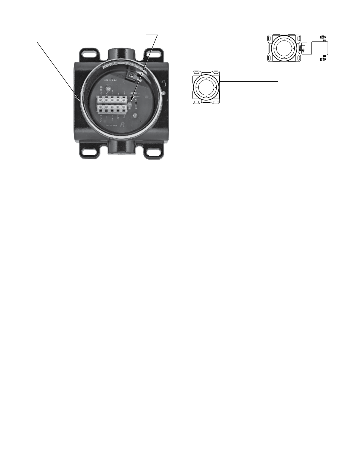
For complete approval details for the PIRVOLHV Process
Gas Monitor and the PointWatch Termination Box Model
PIRTB, refer to the appropriate Appendix:
Appendix A - CSA
Appendix B - ATEX/CE
Appendix C - IECEx
WARNING
Always ensure that the detector/termination
box hazardous (classified) location ratings are
applicable for the intended use.
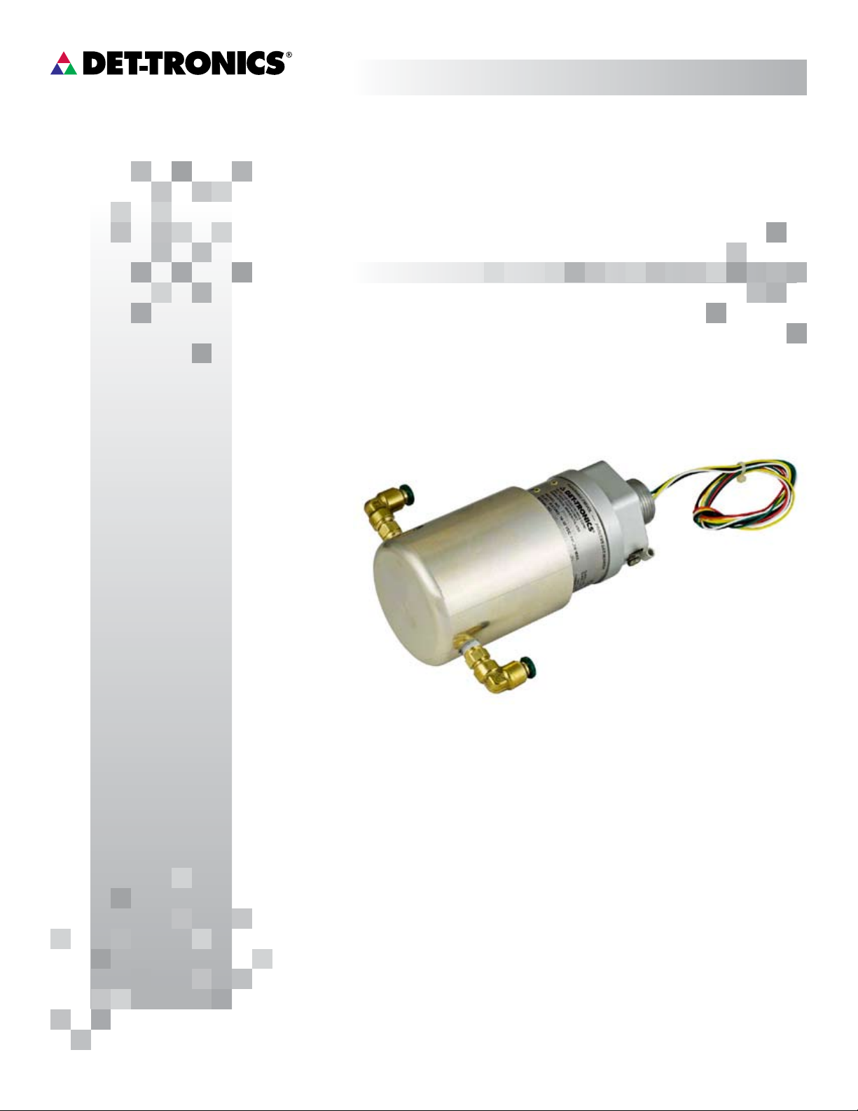
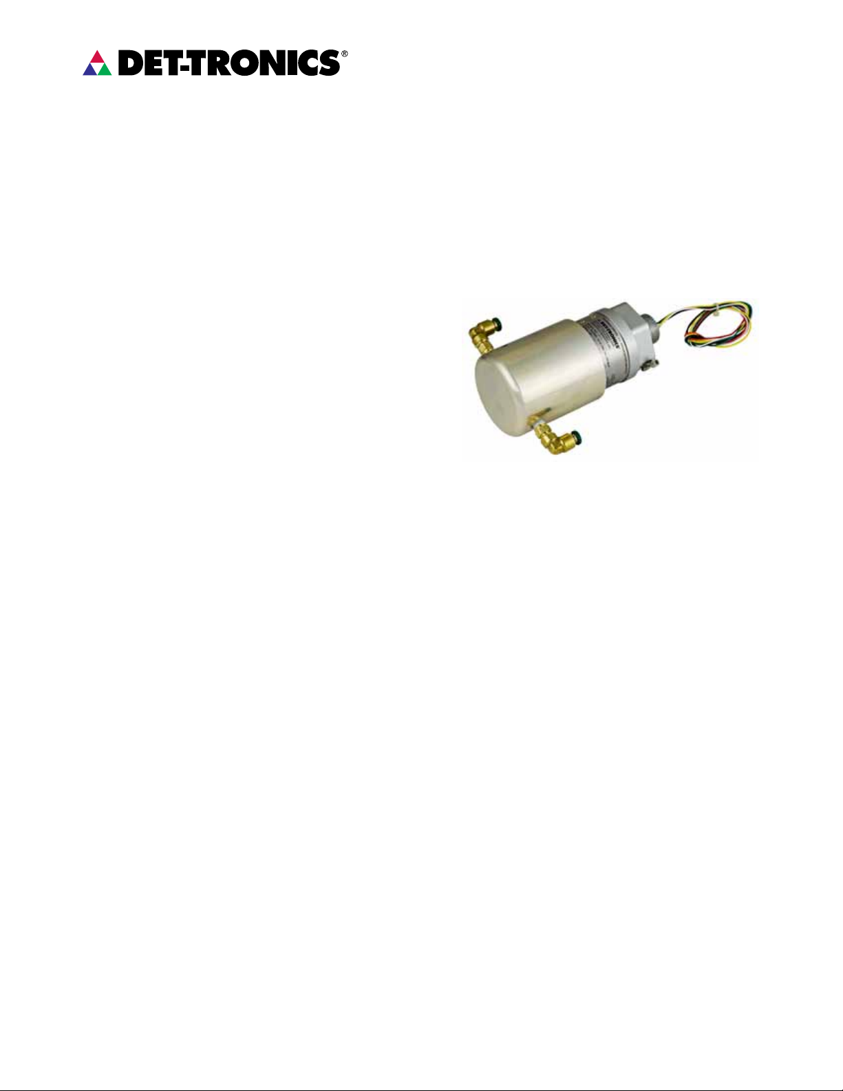
DESCRIPTION
DETECTION METHOD
PIRVOLHV operates on the infrared absorption
principle. A beam of modulated light is projected
from an internal infrared source to a reflector, which
sends it back to a pair of infrared sensors. One of the
sensors is designated reference and the other active,
with different optical filters in front of the two sensors to
make them selective to different infrared wavelengths.
The reference wavelength is unaffected by combustible
gases, while the active wavelength is absorbed by
combustible gases. The ratio of the active to the
reference wavelength is computed within the PIRVOLHV
to determine the concentration of gas present. This
value is then converted into a 4 to 20 mA current output
for connection to external display and control systems.
CURRENT LOOP OUTPUT
During normal operation, the PIRVOLHV has a 4 to 20 mA
current output that is proportional to gas concentrations
from 0 to 100% by volume propane. A current output less
than 4 mA indicates a fault condition (see Table 1).
SIGNAL DISPLAY DEVICE
If a local or remote digital display for indication of detected
gas concentration is required, it is recommended to utilize
a scalable display device with a clearly marked unit of
measurement in % by volume. Under no circumstances
should a % LFL unit of measure display module be used
to display the PIRVOLHV signal output.
OPERATING MODES
Warmup
When power is applied to the PIRVOLHV, it enters a
Warmup mode (for approximately one minute) in which
it performs diagnostic checks and allows the sensors
to stabilize before beginning normal operation. The
current output during this period is 0 mA. At the end of
the warmup period with no faults present, the PIRVOLHV
automatically enters the Normal operating mode. If a
fault is present after the warmup, the current output will
indicate a fault.
Normal
In the normal operating mode, the 4 to 20 mA signal
level corresponds to the detected gas concentration.
The PIRVOLHV continuously checks for system faults or
initiation of calibration, and automatically changes to the
appropriate mode.
Fault
Faults detected during warmup, normal operation, or
calibration are indicated by the current loop output as
shown in Table 1.
Calibration
The PIRVOLHV is calibrated at the factory for detection
of propane. No field calibration is required under normal
circumstances.
In the event the PIRVOLHV optics are fouled and complete
optics disassembly for cleaning is required, device re-
zeroing may be required after re-assembly. Refer to the
“Calibration” section for details.
NOTE
A momentary connection of the calibration lead
wire to DC negative (common) of the power
supply initiates the zero and span calibration
sequence. When wiring the PIRVOLHV, use care
to isolate it from accidental contact with the PIRTB
and/or other conductors.
FM
APPROVED
®
FM
APPROVED
®

5
3.1 95-8632
INSTALLATION
DEVICE MOUNTING ORIENTATION
It is highly recommended that the PIRVOLHV be
installed in the horizontal position. See Figure 5.
TERMINATION BOXES (PIRTB)
The PIRVOLHV is designed to be threaded into a
termination box, which is then mounted to a solid,
vibration-free wall or post.
Det-Tronics offers the Model PIRTB termination box in two
styles for use specifically with the PIRVOLHV:
• Tall Cover Model includes a window. See Figure 6.
• Short Cover Model uses solid cover. See Figure 7. This
model can also be used for detector separation.
The PIRTB terminals are UL/CSA rated for 14 to 22 AWG
wire, and DIN/VDE rated for 2.5 mm2wire.
GENERAL WIRING REQUIREMENTS
NOTE
The wiring procedures in this manual are intended
to ensure proper functioning of the device under
normal conditions. However, because of the
many variations in wiring codes and regulations,
total compliance to these ordinances cannot be
guaranteed. Be certain that all wiring complies
with applicable regulations relating to the
installation of electrical equipment in a hazardous
area. If in doubt, consult the authority having
jurisdiction before wiring the system.
The use of shielded cable in conduit or shielded armored
cable is recommended for optimum RFI/EMI protection.
In applications where the wiring cable is installed in
conduit, the conduit must not be used for wiring to
other electrical equipment. To assure proper operation,
the resistance of the connecting wire must be within
the specified limits. The maximum distance between
the PIRVOLHV and power source is determined by the
power supply capability and wire size. See Figure 2
to determine the proper wire size and maximum wiring
distance allowed.
It is important that moisture not be allowed to come in
contact with the electrical connections of the system.
The use of proper piping techniques, breathers, glands,
and seals are required to prevent water ingress and/or
maintain the explosion-proof rating.
CORRECT INCORRECT
Figure 5—Recommended Orientation of PIRVOL

6
3.1 95-8632
WIRING PROCEDURE
IMPORTANT
Do not apply power until the wiring procedure is
complete and has been veried.
1. Locate the sensor where it will be accessible for
maintenance. Excessive heat or vibration can result
in premature failure of any electronic device and
should be avoided if possible.
2. The PIRTB should be electrically connected to earth
ground.
3. Figure 8 shows typical wiring for stand alone
operation. Figure 9 shows typical wiring for
PIRVOLHV with Det-Tronics’ PIRTB. Figure 10
shows the wiring terminals located inside the PIRTB.
The PIRVOLHV wiring color code is:
Red lead = +24 volts dc
Black lead = – (common)
White lead = 4 to 20 mA signal output
Yellow lead* = Calibration input
Green lead = Chassis ground
* If the calibration wire (yellow lead) is not being
used, do not connect this wire to ground. Trim
excess length and insulate wire so no shorting
can occur.
Figure 6—Tall Cover PIRTB with Window
Figure 7—Short Cover PIRTB
Figure 9—Typical PIRVOL Wiring, with PIRTB
PIRTB TERMINATION BOX
D1756
PIRVOL
PROCESS MONITOR
GREEN
YELLOW
WHITE
BLACK
RED
SPARE
CAL
4 – 20
RET
+24
CHASSIS
CAL
4 – 20
RET
+24
24 Vdc
4-20 mA IN
–
+
Figure 8—Typical PIRVOL Wiring, Stand Alone Conguration
–
RED
BLACK
WHITE
YELLOW
GREEN
4 TO 20 mA
PIRVOL
+
B2031
NOTES: CALIBRATION PUSHBUTTON, CURRENT METER
AND POWER SUPPLY ARE NOT SUPPLIED.
CALIBRATE SWITCH SHOWN INSTALLED, HOWEVER,
FIELD CALIBRATION IS NOT REQUIRED UNDER
NORMAL CIRCUMSTANCES.
24 VDC
POWER SUPPLY
–
+
CALIBRATE

7
3.1 95-8632
DETECTOR SEPARATION (OPTIONAL)
In applications where the PIRVOLHV must be installed
in a different location from a control device (such as a
transmitter), a PIRTB termination box must be installed at
the PIRVOLHV location to make the electrical connection.
Refer to Figure 11 for a typical separation diagram.
Wiring Requirements for Detector Separation
Shielded four wire cable is recommended for connecting
the PIRTB to the transmitter. Cable with a foil shield is
recommended. The shield of the cable should be open
at the PIRTB and connected to earth ground at the
transmitter termination box. Ensure that the shield wire is
clipped short and insulated with electrical tape to prevent
accidental grounding at the open end.
The maximum distance between the PIRTB and the
transmitter is limited by the resistance of the connecting
wiring, which is a function of the gauge of the wire being
used.
NOTE
It is important to maintain a minimum of +18 volts
dc (including ripple) at the PIRVOLHV. When
determining the appropriate wire size for the
installation, refer to Figure 2. Be sure to take into
account the distance from the power supply to
the PIRVOLHV or to the transmitter and then to the
PIRVOLHV to ensure that the power requirements
are met.
Mounting and Connecting Procedure
for Detector Separation
The PIRTB should be mounted to a solid, vibration-free
wall or post. The termination box should be electrically
connected to earth ground.
1. Lubricate the sensor threads with low vapor
pressure silicone grease, then install the sensor in
the conduit entry of the PIRTB. It should be tight to
ensure an explosion-proof installation, however, do
not overtighten.
2. Connect the PIRVOLHV wires to the terminal strip in
the PIRTB.
3. Connect the leadwires from the transmitter to the
appropriate terminals inside the PIRTB. Do not
ground the shield at the PIRTB. Ground the shield at
the transmitter end only.
4. Check the connections inside the PIRTB and place
the cover on the termination box.
5. Mount and wire the transmitter as described in the
instruction manual provided by the manufacturer.
CALIBRATE SWITCH
C2056
HOLD CALIBRATION MAGNET
AT OUTSIDE BASE OF TERMINATION
BOX AT THIS LOCATION
TO ACTIVATE CALIBRATION SWITCH
REMOTE LED
Figure 10—PIRTB Terminals and Calibration Switch
PIRTB
TERMINATION
BOX
SUITABLE WIRING.
MUST MEET ALL LOCAL CODES.
CONTROL DEVICE,
SUCH AS TRANSMITTER
PIRVOL
PROCESS MONITOR
D2030
Figure 11—Detector Separation

8
3.1 95-8632
STARTUP PROCEDURE
NOTE
Caution should be exercised when applying this
and any electronic device to explosive vapor
extraction and measurement applications.
Typical hazards in these applications include
small tting vapor leaks, resulting in dangerous
gas concentrations near or within the system
enclosure. Any spark or arc may result in a re
or explosion in these conditions. Always inspect
all ttings for leakage before commissioning, and
always remove power from all electronic devices
before performing maintenance on the vapor
extraction system tubing, ttings, and hardware.
1. Inhibit the output loads that are actuated by the
system to prevent activation of these devices.
2. Check that the PIRVOLHV has been wired
properly.
3. Apply power to the system and allow the
PIRVOLHV to operate for a minimum of 2 hours,
then check zero and verify gas response.
4. Place the system in normal operation by
reactivating the output loads.
TROUBLESHOOTING
Refer to Table 2 to isolate and correct malfunctions with
the PIRVOLHV.
MAINTENANCE
It is recommended to have spare IR Modules on hand
(see “Spare Parts” section). Use Table 2 to isolate and
correct malfunctions.
IMPORTANT MAINTENANCE NOTES
• Hydrocarbon-based grease emits hydrocarbon
vapors, which will be measured by PIRVOLHV,
resulting in elevated gas concentration
readings. Use only silicone-based grease (not
hydrocarbon-based grease) when lubricating
threads on the PIRVOLHV and associated
termination box. A suitable grease is listed under
“Spare Parts” in the Ordering Information section
of this manual.
• It is recommended to keep spare IR modules
(See “Spare Parts” section) for eld replacement
in the event of a malfunction.
Table 2—Troubleshooting Table
Current Level Status Corrective Action
2.4 to 3.9 mA Negative Zero Indication This fault can be caused by the presence of
background gas during calibration. Ensure that
background gas is not present and recalibrate the
unit. If fault does not clear, perform disassembly
and cleaning procedure, then recalibrate. If fault
still does not clear, replace electronics assembly.
1.6 mA Calibration fault Repeat zero calibration. If the condition persists,
replace electronics assembly.
1.0 mA Fouled optics Perform disassembly and cleaning procedure,
then recalibrate.
0.8 mA +24 Vdc line low (less than +17.5 Vdc) Ensure that input voltage is correct and that power
connections are good. If fault does not clear,
replace the electronics assembly.
0.6 mA Calibrate input active at power-up Ensure that calibration line is not shorted and that
the calibration switch is open. If fault does not
clear, replace the unit.
0.4 mA Active channel fault Replace electronics assembly.
0.2 mA Reference channel fault Replace electronics assembly.
0.0 mA CPU system fault, warmup Ensure that power is applied and that the warmup
period is complete (1 minute). If fault does not
clear, replace the unit.

9
3.1 95-8632
DISASSEMBLY AND CLEANING PROCEDURE
The PIRVOLHV should be inspected periodically to ensure
that its performance is not impaired by fouled optics or by
clogging of the sample draw cup or hydrophobic filter.
Inspection and/or periodic maintenance involves three
different areas.
IMPORTANT
Remove power before disconnecting and
removing the PIRVOLHV for maintenance.
Sample Draw Cup. Perform a visual inspection of the
sample draw cup and associated plumbing, and clean
as required. External filtration of sample stream is
recommended.
Hydrophobic Filter. The flow of gas through the
filter can be inhibited by an accumulation of mud or
other contaminants. To inspect the hydrophobic filter,
disassemble the PIRVOLHV as described below. If the
filter appears to be fouled, replace it.
Optics. Cleaning of the optical surfaces is required only
if an optical fault is indicated (1.0 mA current output signal
from the PIRVOLHV). This procedure is most easily
accomplished on a bench.
Required materials: Clean, flat work surface, foam tipped
swabs (no cotton), isopropyl alcohol, screwdriver.
CAUTION
The PIRVOLHV contains semiconductor devices
that are susceptible to damage by electrostatic
discharge. An electrostatic charge can build
up on the skin and discharge when an object is
touched. Therefore, use caution when handling
the device, taking care not to touch electronic
components or terminals. If the electronics
assembly is removed, it should be placed in an
anti-static bag or box while stored or transported.
A static safeguarded work area is highly
recommended (if available) for disassembly and
cleaning of the PIRVOLHV.
1. Remove the sample draw cup from the front of the
PIRVOLHV by pulling it straight off the electronics
assembly (no tools needed). See Figure 12.
2. Perform a visual inspection of the sample draw
cup and associated plumbing, and clean as
required. Also inspect the two O-rings inside the
sample draw cup and clean, lubricate or replace
as required.
3. Loosen the two captive screws on top of the
mirror assembly (Figure 12) and remove the
mirror assembly and hydrophobic filter from the
electronics assembly.
4. Thoroughly douse the interior of the mirror
assembly as well as the foam tipped swab
with isopropyl alcohol. Use the swab to gently
cleanse the surfaces of the reflecting mirrors
inside the mirror assembly. After cleaning with
the swab, flush out the mirror assembly using
a liberal amount of isopropyl alcohol. Tip the
mirror assembly with mirror openings downward
to remove accumulated isopropyl alcohol and
particle contaminants. Repeat the alcohol flush
to remove any remaining contaminants. Allow the
mirror assembly to air dry in a dust-free location.
IMPORTANT
Do not insert any sharp object into the mirror
assembly. Scratching of the mirrors will void the
PIRVOLHV warranty. Do not use cotton tipped
swabs or buds as they are likely to leave fiber
residue.
5. Clean the two windows on the electronics
assembly using the procedure described above.
When the mirror assembly and electronics
assembly are thoroughly dry, proceed with
re-assembly.
6. Slide a new hydrophobic filter over the end of the
mirror assembly, then carefully seat the mirror
assembly and hydrophobic filter against the base
of the electronics assembly. Be careful not to
crumple or fold the hydrophobic filter.
7. Tighten the two captive screws on the top of the
mirror assembly. Tighten the screws evenly. Do
not over-tighten (6 inch-pounds recommended).
8. Slide the sample draw cup back onto the
PIRVOLHV.
9. Check for leaks around the PIRVOLHV sample
draw cup.

10
3.1 95-8632
CALIBRATION
In the event the PIRVOLHV optics are fouled and complete
dis-assembly is required for cleaning, a zero calibration
of the device may be required. This procedure ensures
the signal output level is at 4 mA, and does not require
application of span gas.
NOTE
Zero drift will be indicated by a constant offset in
one direction either above or below 4 mA. The
presence of background gas would be indicated
by a small but constantly changing output.
IMPORTANT CALIBRATION NOTES
Ensure that the detector has been operating for at
least two hours before calibrating.
Do not open the explosion-proof enclosure
when power is applied to the system unless the
appropriate permits have been procured.
Calibration Procedure
To perform a zero calibration of the PIRVOLHV, follow the
sequence described in Table 3.
NOTE
The calibration sequence is initiated by
momentarily connecting the calibration lead to
the negative lead (common) of the power supply
using either the Cal Magnet or an external switch.
If the Det-Tronics PIRTB with magnetic Cal Switch
is being used, this is accomplished by holding
the Cal Magnet near the side of the termination
box for one second. The location of the Cal
Switch is shown in Figure 10. An alternate way
of accomplishing this is to install a pushbutton
switch between the yellow lead and the power
supply common.
Factory calibration is recommended for complete device
calibration. Contact Det-Tronics for additional information.
MIRROR ASSEMBLY
MIRRORS (2)
WINDOWS
ELECTRONICS ASSEMBLY
HYDROPHOBIC FILTER
SAMPLE DRAW CUP
UL APPROVED O-RINGS
C2032
Figure 12—PIRVOLHV Disassembly for Cleaning

11
3.1 95-8632
REPLACEMENT PARTS
The PIRVOLHV is not designed to be repaired in the field.
If a problem should develop, refer to the Troubleshooting
section. If it is determined that the problem is caused by
an electronic defect, the device must be returned to the
factory for repair.
DEVICE REPAIR AND RETURN
Prior to returning devices, contact the nearest local
Detector Electronics office so that a Return Material
Identification (RMI) number can be assigned. A
written statement describing the malfunction must
accompany the returned device or component to
assist and expedite nding the root cause of the
failure.
Pack the unit properly. Always use sufficient packing
material. Where applicable, use an antistatic bag as
protection from electrostatic discharge.
NOTE
Det-Tronics reserves the right to apply a service
charge for repairing returned product damaged as
a result of improper packaging.
Return all equipment transportation prepaid to the factory
in Minneapolis.
NOTE
It is highly recommended that a complete spare
be kept on hand for eld replacement to ensure
continuous protection.
Table 3—Calibration Sequence
Description Current
LED
Operator Action
Normal operation/no gas present 4.0 mA Off
If the possibility of background gases exists,
purge the sensor with clean air to ensure accurate
calibration.
Initiate calibration
2.2 mA On steady Initiate the calibration sequence by holding the
calibration magnet against the side of the termination
box or activating the external calibrate pushbutton for
one second.
Zero calibration complete
2.0 mA Flashing Re-apply magnet (or activate switch) for one second.
Span calibration is not required. Device will revert to
live operation using new zero level and original span
level from factory calibration.
Calibration fault indication
1.6 mA Off See Troubleshooting Table.
NOTE: Failure to re-apply magnet to set zero level will result in Fault status if span gas is not applied. Span gas is typically
applied at the factory only.

12
3.1 95-8632
ORDERING INFORMATION
PIRVOLHV PROCESS GAS MONITOR
Refer to the PIRVOLHV Model Matrix.
REPLACEMENT IR MODULE
Without cup, for field replacement only.
Specify:
– Aluminum or stainless steel
– 3/4 inch or M25
PIRTB TERMINATION BOXES
Short Cover Termination Box (solid cover, with 5 ports)
Part Number Description
006414-016 3/4 inch entries, aluminum
006414-017 3/4 inch entries, stainless steel
006414-018 M25 entries, aluminum
006414-019 M25 entries, stainless steel
Tall Cover Termination Box (with window and 5 ports)
Part Number Description
006414-020 3/4 inch entries, aluminum
006414-021 3/4 inch entries, stainless steel
006414-022 M25 entries, aluminum
006414-023 M25 entries, stainless steel
STOP PLUGS AND REDUCERS
Part Number Description
101197-001 Stop plug, 3/4 inch, aluminum
101197-004 Stop plug, 3/4 inch, stainless steel
103517-001 Stop plug, M25, aluminum, IP66
101197-003 Stop plug, M25, stainless steel, IP66
102804-001 Reducer, M25 to M20, aluminum
102804-003 Reducer, M25 to M20, stainless steel
SPARE PARTS
Part Number Description
007128-001 Aluminum Sample Draw Cup
with O-Rings and Fittings
007128-003 Stainless Steel Sample Draw Cup
with O-Rings and Fittings
007128-002 O-Ring Kit (UL)
006297-003 Hydrophobic Filter
006680-001 Silicone Grease
ASSISTANCE
For assistance in ordering a system to meet the needs of
a specific application, contact:
Detector Electronics Corporation
6901 West 110th Street
Minneapolis, Minnesota 55438 USA
Operator: (952) 941-5665 or (800) 765-FIRE
Customer Service: (952) 946-6491
Fax: (952) 829-8750
Web site: www.det-tronics.com
E-mail: det-tronics@det-tronics.com
PIRVOLHV MODEL MATRIX
MODEL DESCRIPTION
PIRVOL Point Infrared Volumetric Process Gas Monitor
TYPE APPLICATION
HV Heavy Hydrocarbons
TYPE MATERIAL
AAluminum
SStainless Steel
TYPE THREAD TYPE
33/4” NPT
2M20
TYPE SAMPLING CUP
AWith Sampling Cup
BWithout Sampling Cup (replacement part only)
TYPE APPROVALS
CCSA
EATEX/CE/IECEx

13
3.1 95-8632
APPENDIX A
CSA APPROVAL
PIRVOLHV Process Gas Monitor
CLASS 2258 02 -PROCESS CONTROL EQUIPMENT - For Hazardous Locations
Class I, Div. 1, Groups B, C & D (T5); Class I, Div. 2, Groups A, B, C & D (T3C).
PointWatch Termination Box Model PIRTB
CLASS 4828 01 -SIGNAL APPLIANCES - Combustible Gas Detection Instruments - For Hazardous Locations
Class
I
, Div. 1, Groups B, C & D (T6). Class
I
, Div. 2, Groups A, B, C & D (T6).

14
3.1 95-8632
APPENDIX B
ATEX / CE APPROVAL
ATEX CERTIFICATION
PIRVOLHV Process Gas Monitor
0539
FM
APPROVED
®
II 2 G
Ex d IIB+H2T4-T6 Gb
DEMKO 09 ATEX 148373X
T6 (Tamb = –55°C to +50°C)
T5 (Tamb = –55°C to +60°C)
T4 (Tamb = –55°C to +75°C)
IP66.
EN Standards:
EN 50270: 2006
EN 60079-0: 2009
EN 60079-1: 2007
EN 60529: 1991+A1: 2000.
Read and understand instruction manual before operating.
Special Conditions for Safe Use (‘X’):
The Process Gas Monitor, Model PIRVOL, has a threaded wire feed through incorporating flying leads. This feed
through is to be screwed into the cable entry opening of a suitable certified (Ex ‘d’ or Ex ‘e’) enclosure in which the
flying leads are to be terminated.
In order to maintain the Ingress Protection rating IP66, the back end of the Process Gas Monitor, Model PIRVOL, with
the flying leads is to be screwed into a suitable certified flameproof enclosure with an Ingress Protection rating of at
least IP66.
CE MARK
The PIRVOLHV Process Gas Monitor was tested and found to be compliant with EN50270 when wired in conduit or with
shielded cable. All screen drains shall be terminated to the chassis.
PointWatch Termination Box Model PIRTB
0539
FM
APPROVED
®
II 2 G
Ex d IIC T5-T6 Gb
EN 60079-29-1
DEMKO 02 ATEX 131326
T6 (Tamb = –55°C to +60°C)
T5 (Tamb = –55°C to +75°C)
IP66.
EN Standards: EN 60079-0: 2009
EN 60079-1: 2007
EN 60529: 1991+A1: 2000
EN 60079-29-1: 2007.
All cable entry devices and blanking elements shall be certified in type of explosion protection flameproof enclosure
‘d’, suitable for the conditions of use and correctly installed. Unused apertures shall be closed with suitable certified
blanking elements.
For ambient temperatures below –10°C and above +60°C, use field wiring suitable for both minimum and maximum
ambient temperatures.

15
3.1 95-8632
APPENDIX C
IECEx APPROVAL
PIRVOLHV Process Gas Monitor
IECEx ULD 11.0007X
Ex d IIB+H2T4-T6 Gb
T6 (Tamb = –55°C to +50°C)
T5 (Tamb = –55°C to +60°C)
T4 (Tamb = –55°C to +75°C)
IP66.
IEC Standards:
IEC 60079-0: 2007
IEC 60079-1: 2007
IEC 60529, 2.1.ed.+Corr. 1:2003+2:2007.
CONDITIONS OF CERTIFICATION:
The Process Gas Monitor, Model PIRVOL, has a threaded wire feed through incorporating flying leads. This feed
through is to be screwed into the cable entry opening of a suitable certified (Ex ‘d’ or Ex ‘e’) enclosure in which the
flying leads are to be terminated.
In order to maintain the Ingress Protection rating IP66, the back end of the Process Gas Monitor, Model PIRVOL, with
the flying leads is to be screwed into a suitable certified flameproof enclosure with an Ingress Protection rating of at
least IP66.
PointWatch Termination Box Model PIRTB
IECEx ULD 10.0002
Ex d IIC T5-T6 Gb
T6 (Tamb = –55°C to +60°C)
T5 (Tamb = –55°C to +75°C)
IP66.
IEC Standards: IEC 60079-0: 2007
IEC 60079-1: 2007
IEC 60529, 2.1.ed.+Corr. 1:2003+2:2007.
All cable entry devices and blanking elements shall be certified in type of explosion protection flameproof enclosure
‘d’, suitable for the conditions of use and correctly installed. Unused apertures shall be closed with suitable certified
blanking elements.
For ambient temperatures below –10°C and above +60°C, use field wiring suitable for both minimum and maximum
ambient temperatures.

95-8632
Det-Tronics and the DET-TRONICS logo are registered trademarks or trademarks of Detector Electronics Corporation in the United States,
other countries, or both. Other company, product, or service names may be trademarks or service marks of others.
© Copyright Detector Electronics Corporation 2012. All rights reserved.
Detector Electronics Corporation
6901 West 110th Street
Minneapolis, MN 55438 USA
T: 952.941.5665 or 800.765.3473
F: 952.829.8750
W: http://www.det-tronics.com
X3301 Multispectrum
IR Flame Detector
PointWatch Eclipse®
IR Combustible Gas Detector
Eagle Quantum Premier®
Safety System
FlexVu®Universal Display
w/ GT3000 Toxic Gas Detector
Table of contents
Other Det-Tronics Measuring Instrument manuals
Popular Measuring Instrument manuals by other brands

Silvercrest
Silvercrest SND 3600 C2 operating instructions

phase II+
phase II+ PHT-2000 instruction manual

PerkinElmer
PerkinElmer FL 6500 installation instructions

ACU-RITE
ACU-RITE 325 instruction manual

Isotech
Isotech PEGASUS PLUS 1200 Series Handbook

Check-line
Check-line PaintCheck operating instructions