Detech OneGateWL User manual

DeTech1OneGateWL REV.D 10/04/19
OneGateWL
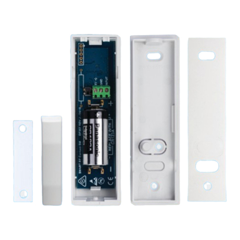
Perimetral active sensor, multifunctioning, via radio
Bidirectional FM 868
Magnetic contact for openings,
seismic for detection of broken
windows or for antirip.
Available in white and mahogany
CHARACTERISTICS
✓Magnetic sensor with Hall effect
✓Seismic detector
✓Anti-rip circuit
✓Roller pulse-counter input
✓Antitampering circuit
✓You can position the magnets on both sides
✓Alarms displaying
✓Power supply: 3,6v- 1,2 Ah lithium battery 1/2AA
ER14250
✓3 years of autonomy (at standard use).
✓Radio Freq. 868MHz-FM.
✓NC ausiliary input
1 Installation guide
! WARNING: Before every trial, connect the
sensor to the receiver
The sensor can be installed on window frames as a magnetic or
seismic contact, and on windows as a seismic as an alarm for
broken windows. Remove the circuit and secure the bottom
with screws or glue.
1.1 Magnetic contact installation
If the magnetic contact isn’t
requested, skip this paragraph.
Position the magnet on the right
and/or on the left, like shown in
the picture, on the door you
want to check on.
Align the magnet poistioning at a maximum distance of 1 cm.
To balance the eventual difference between the sensor and the
magnet, open the magnet-holder and position the magnet in
one of the three positions shown.
1.2 Seismic installation
When this function isn’t needed, skip this paragraph.
DIP 2 in Pos ON Activated seismic alarm
The sensor is able to identify strong vibrations hitting the surface
you need to protect. Useful for windows, fixtures and grates
protection.
2.BATTERY POSITIONING
Secure the battery in its housing.
3SENSOR ASSOCIATION
This can take place in the system, generating a Tamper
alarm(r leasing the Tamper button) or inserting the battery
in the acquisition phase.
4. RADIO COVERAGE TEST
When the battery is disconnected, push the Tamper and
insert the battery. When the GREEN LED will blink release
the Tamper. If the GREEN LED blinks, it reports a good radio
signal, when the RED and GREEN LEDs blink, it means you have a
radio signal that is not adequate. In case of no blinking, you have
no signal.To end the test, push the Tamper or wait for 4 minutes.
5. INITIALIZATION
Once the sensor is linked and the radio coverage is verified, start
the initialization. Remove the battery and set up the operative
mode, close the eventual door with the magnet and insert the
battery. The sensor will start an autonomous acquisition for 2
minutes. The LEDs will blink alternately If there is a magnet, the
blinking will increase after 20 secs. Do not change the operative
conditions, (the door must be closed and the sensor mustn’t be
subjected to vibrations Wait until the GREEN and RED LEDs will
switch on, then push the Tamper and wait for the switching off
of the LEDs. This will assure the exit from the acquisition mode.
N.B. Everytime, with opened Tamper, the sensor will be
powered up, the sensor enters a magnet acquisition mode.
The sensor is set
up with the antirip
technology
disabled, with the
seismic sensitivity
calibrated, with
roller sensitivity
set on 15 impulses
and displaying ON.
When a variation
of these
configurations is
requested, check
the paragraph on
programming (n.6)
Otherwise, secure
the upper lid and
verify the correct functioning through LED reports.

DeTech2OneGateWL REV.D 10/04/19
6 Programming and calibrations
DIP 1 Pos ON LED Off disabled
displaying
DIP 2 Pos ON seismic mode is on
DIP 3 Pos ON
Roller impulses calibration
DIP 4Pos ON Antirip mode is on
Default: DIP in Pos OFF
6.1 LED OFF
DIP 1 PosON
If you want to disable the LED displaying,
set the DIP 1 on ON and close the
cover,the leds will go off in 2 minutes, to
verify the right functioning of the sensor.
6.2 Seismic calibration
The sensor has its calibrated sensitività by
default.If you want to change it, follow these steps
position the DIP on OFF. Push the Tamper key and position
the DIP 2 on ON, release the Tamper and wait fot the GREEN
LED to turn on. This confirms the system is now in
calibration mode. Hit the frame or the window 10 times
(you choose the intensity you need). Every hit the system
acquires will be confirmed by the blinking of the GREEN LED.
The sensor sets the new sensitivity limits, based on the average
hit, for the alarm condition. The calibration will end when the LEDs will
blink alternately, otherwise the previous limits will stay put. To restore
the initioal sensitivity, enter the calibration mode and push the Tamper
key.
6.3CV Rapid contact (Roller)
Connect the roller between the clamp (-) and (CV-IN); the alarm is
reported on the CV-OUT output. It’s possible to change the
number of impulses through the following procedure: while
pushing theb Tamper, set the DIP3 on ON; the leds will blink to
show the system is in programming mode. Release the Tamper and
generate the number of impulses you want: at every impulse, the
GREEN LED will blink to confirm the right acquisition of the
impulses. Position, now, the DIP3 on OFF
6.4Antirip
DIP 4 Pos On
Any attempt of removal from its position, will generate a Sabotage
alarm.
ADDITIONAL INPUTS (NC)
On this clamp, it’s possible to connect an outern contact that will work
in AND with the main contact.
LOW BATTERY report
The low battery report is shown on the sensor through the blinking of
the RED LED.
At the same time, the sensor will send the low battery status to the
DeUnire, on the BATT LOW output.
Change the battery within 15 days.
7BATTERY REPLACEMENT
To replace the battery position the alarm system in MAINTENANCE mode,
open the sensor, remove the battery, push the tamper button repeatedly and
insert the new battery and close back the lid and the eventual door with the
magnet. The sensor will predispose to heating and after the SELF TEST,
afterwards it will be enabled to operative functioning. This will take 2 minutes.
Once the lid is closed, you can exit from MAINTENANCE mode on the board.
8 WARNING:
•explosion danger if the battery isn’t replaced correctly.
Replace it only with an equal or equivalent type.
•In case the battery shows leakage of liquid, change it
immediately. Afterwards, clean your hands if you touched the
fluid.
Warning: Because of its small dimensions, the product can be ingested
easily. Keep away from children.
11 INFORMATION RELATING TO THE DISPOSAL (RAEE GUIDELINE)
•Warning: don’t throw this product in the normal trash bin!
•The electrical and electronical equipment must be managed
separately in accordante with the legislation requiasting the
management, the disposal and recycling of such products
DISPOSAL OF THE BATTERY:
Warning: the battery contains polluting substances, therefore it must
be put in special predisposed to the collecting and disposal of polluting
waste.
The correct disposal of this product will contribute to the right
treatment, recovery and disposal, preventing an eventual negative
impact on the environment and
on human health. Penalties may
be imposed in case of non
compliance of the 151/05
Legislative Decree.
Alarm display
Alarm
Green
led
Red
led
Magnetic
ON
OFF
Seismic
OFF
ON
Rapid contact
Lamp
Lamp
Aux contact
Lamp
ON
Tearproof
Lamp
OFF
Tamper
ON
ON
DATA
Power supply
½ AA 3,6 V
MAX absorption
10 mA
Absorption at rest
30 uA
Alarm length
3 sec.
Working temperature
-5°C / +55°C
Transmission frequency
868 FM
Battery
3,6 V ½ AA 2,4 A Litio
Battery life
3 anni
Humidity
95%
D e T e c h s r l
Via Enzo Benedetto 27/b 00173 Roma Italia
Tel 06/72016428info@detechsrl.itwww.detechsrl.it
Garanzia:il prodotto è
garantito per 5 anni
Other Detech Accessories manuals
