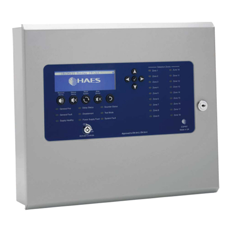
Detnov CAD-150-R User manual

ES
Repetidores analógicos
MANUAL DEL INSTALADOR

2
ES
1 - El Repetidor Analógico
1.1 - El Repetidor Analógico
En este punto se ofrece una descripción de todos los componentes del equipo y de los
indicadores y teclas del panel de control.
Indicaciones del teclado
1 Pantalla matricial 12 Indicador Sirenas Temporizadas
2 Teclas navegación 13 Indicador Fallo Sirenas
3 Indicador de Alarma zona 14 Indicador Salida Anuladas
4Indicador Avería-Desconexión-Prueba Zona 15 Indicador de Servicio
5Indicador-Tecla Activar Sirenas 16 Indicador de Alarma
6 Indicador-Tecla Silenciar Sirenas 17 Indicador de Anular
7 Indicador-Tecla Silenciar Repetidor 18 Indicador de Fallo
8 Tecla de Reset 19 Indicador de Prueba
9 Indicador Fallo Sistema 20 Indicador de Fuera Servicio
10 Indicador Fallo Alimentación 21 Teclado cursores y Enter
11 Indicador Fallo derivación a tierra 22 Teclado Alfanumérico

3
ES
1
2 3 4 5
10
6
7 8 911
12 13 14 15
16
17(bateríasde2Ah) 17(bateríasde7Ah)
1 Puerto de comunicaciones RS485
2Conector de Alarma
3Conector de Avería
4 Sirena 1
5 Sirena 2
6 Salida Auxiliar de 24V
7 Fusible de la Sirena 1 (0,5A)
8 Fusible de la Sirena 2 (0,5A)
9 Fusible de la Salida Auxiliar de 24V (0,5A)
10 Contraste
11 Batería RTC (reloj interno)
12 Conector USB
13 Conector de Batería
14 Fusible de Batería (2A)
15 Pulsador de funcionamiento con Batería
16 Conector a la red eléctrica con fusible (4A)
17 Baterías (izquierda: baterías de 2Ah / derecha: baterías de 7Ah).

4
ES
2 - Guía de Instalación
2.1 - Selección de Idioma
Los repetidores se han diseñado para que personalizar el idioma resulte una tarea
sencilla. En la hoja de idiomas adjunta a este manual se encuentras los insertables
correspondientes a varios idiomas. Seleccione el idioma que precise y coloque el
insertable en la ranura correspondiente de la parte inferior del panel de control. Las
ubicaciones están señalizadas con las letras A, B y C.
2.2 - Conexionado eléctrico y cableado
Es recomendable que el equipo se alimente y se pruebe antes de conectar ningún
dispositivo. El repetidor debe conectarse a través de un magneto térmico bipolar exterior,
utilizando cable de 1.5 mm2de sección. La tensión de red debe ser de 230VAC.
Para evitar cruces el cable de conexión a la red eléctrica debe ir separado del resto de
líneas.
Si en el lugar de instalación hubiese perturbaciones eléctricas que pudieran alterar el
funcionamiento del equipo se recomienda el uso de ferritas. Colóquelas lo más cerca
posible de los conectores de la placa principal.
Es imprescindible que utilice los oricios marcados en la caja para pasar los cables,
tanto de alimentación como de comunicaciones y sirenas al regletero. Utilice una broca
de corona para perforar la caja e inserte el prensastopa (tipo PG13). Para la entrada del
cable de conexión a la red eléctrica es recomendable utilizar la entrada posterior a la
altura de la regleta de conexión.
Utilice cable apantallado, conectando la pantalla del cable a los bornes correspondientes,
y protéjala para no provocar cruces indeseados. Asegúrese de que la instalación tiene
una conexión a tierra correcta.
2.3 - Alimentación de el repetidor
No realice la instalación del repetidor con la alimentación conectada. Desconecte
siempre el magneto-térmico bipolar exterior antes de manipular el repetidor.
El orden de conexión, para su seguridad, siempre tiene que ser primero la red eléctrica
y posteriormente las baterías. No conecte el repetidor a la red hasta haber completado
la puesta en marcha.
2.4 - Conexión a la red eléctrica
Para asegurar una optima jación del cable de alimentación inserte el cable en la guía
de plástico utilizando las pestañas de la carcasa de plástico y deje el cable de tierra más
largo que el resto. Con estas dos medidas evitaremos que el cable se suelte, en caso
de extracción brusca.
No use nunca el fusible de la regleta de red para conectar y desconectar el repetidor de
la red eléctrica utilice el magneto-térmico.

5
ES
2.5 - Conexión de las baterías
Los repetidores requieren dos baterías de 12V, bien de 2A/h o bien de 7A/h conectadas
en serie. El puente de cable suministrado debe conectarse del polo + de una batería al
polo - de la otra. Las baterías se colocan en el espacio reservado para ellas en la parte
inferior de la caja. Conecte el cable de alimentación al conector de la placa principal y
los terminales del cable al (rojo al + y negro al -) de las baterías
2.6 - Conexión de la red de comunicaciones
La instalación de la red de
comunicaciones es un bucle cerrado,
es decir, el cable de dos hilos debe
salir de la repetidor y volver a él.
Este cable debe ser apantallado
para evitar interferencias.
Conecte los terminales de la regleta RS485 indicados con OUT (B, A y ⏚) a los terminales
correspondientes de la regleta RS485 indicados con IN (B, A y ⏚) del siguiente equipo,
bien sea una central u otro repetidor. Así sucesivamente hasta volver al repetidor.

6
ES
2.7 - Conexión de las Sirenas
El repetidor dispone de 2 salidas de Sirenas, indicadas en la placa base como SND1
y SND2. Cada salida puede alimentar una línea de sirenas con un consumo total de
450mA por línea. Al nal de cada línea deberá conectar una resistencia de 4K7 Ohmios.
En caso de utilizar sirenas o campanas no polarizadas instale un diodo 1N4007 en el
terminal positivo antes del nal de línea para evitar el efecto de la corriente invertida.

7
ES
3 - Guía de puesta en marcha del Sistema
Este capítulo dene paso a paso como se debe realizar una correcta puesta en marcha
de los repetidores.
3.1 - Vericación del sistema
Antes de suministrar la alimentación de red al equipo vericar los puntos que se detallan
a continuación con detenimiento:
• Compruebe que el equipo se ha instalado correctamente.
• Con la ayuda de un multímetro veriqueque no existen cortocircuitos o circuitos
abiertos en las líneas de sirenas. Use el multímetro para comprobar la continuidad de
la línea.
• Verique que las líneas de sirenas tienen las resistencias de nal de línea (4K7
Ohmios)
• Verique las conexiones de salida de la placa base. Compruebe que están
correctamente instaladas.
• Verique que la tensión de red es de 230VAC mediante el uso de un voltímetro y
compruebe que las baterías tienen una tensión superior a 24V.
3.2 - Alimentación del sistema
Una vez revisados todos los puntos descritos anteriormente, el orden correcto para
realizar la conexión es el siguiente:
• Conecte la alimentación de red activando el magneto-térmico bipolar
• Conecte las baterías.
En caso de necesidad, se puede encender el equipo solo con las baterías conectadas
pulsando sobre el botón BAT de la placa principal.
Una vez realizada esta maniobra todos los indicadores del repetidor deberían estar
apagados excepto el verde de servicio.
En caso detectar alguna indicación diferente a las descritas anteriormente, investigue
el origen del problema en la instalación y repare la anomalía antes de continuar (ver el
apartado de problemas comunes).

8
ES
3.3 - Conguración rápida de una Instalación
La conguración básica de la repetidor se puede realizar en su totalidad desde el teclado
del propio repetidor, pero se recomienda utilizar el software de conguración dado que el
proceso será más sencillo y rápido.
Para acceder al menú de conguración debe desbloquear el equipo mediante la
introducción de la clave 2222. A continuación se detallan los pasos para la conguración
rápida:
• Selección del Idioma. Por defecto, los equipos están congurados para trabajar en
Español. Accediendo al menú GENERAL podrá seleccionar el Idioma.
• ConguraciónFechayHora. Para congurar la fecha y la hora del equipo acceda al
menú FECHA Y HORA.
• Nombrar la Instalación. Para editar la información de la instalación y de la empresa de
mantenimiento acceda al menú GENERAL, después al submenú EDITAR INSTALACION.
• Congura un nodo. Acceda al menú de RED y abra el submenú CONFIGURAR
NODO. Elija el tipo de nodo como NORMAL y asigne al repetidor un número de nodo
libre de la red en el submenú DIRECCION.
Una vez realizados todos los pasos expuestos anteriormente, el sistema estará
congurado para proteger la instalación.
3.4 - Prueba del sistema
La comprobación del sistema se hace en base a los siguientes puntos:
• Verique que al provocar una avería se activa el relé de avería.
• Verique que al provocar una alarma se activa el relé de alarma y que se activan las
salidas de sirena una vez transcurrido el tiempo programado de retardo.
Nota: La avería de alimentación puede tardar varios minutos en ser indicada.

9
ES
4 - Manuales
Los manuales están disponibles en el soporte electrónico adjunto en formato PDF. Para
poder visualizar los manuales hace falta tener instalado Adobe Acrobat Reader. Para
descargar gratuitamente Acrobat Reader, visita el sitio web de Adobe.
En caso de cualquier duda sobre el funcionamiento del equipo puede ponerse en
contacto con el servicio técnico o contactar con su distribuidor más cercano.
Códigos de acceso de fábrica
Código acceso nivel usuario 1111
Código acceso nivel instalador 2222

55315502
2019-10-18

GB
Addressable repeater
INSTALLATION GUIDE

2
GB
1 - The Repeater
1.1 - The Repeater
A description of all the equipment components, indicators and control keys is given
below:
Indications Keyboard
1LCD Display 12 Delay ON indicator
2Navigation controls 13 Sounder Fault indicator
3Alarm zone indicator 14 Output disablement indicator
4Fault-disablement-test-zone indicator 15 Service indicator
5Activate sounders control 16 Alarm indicator
6Silence sounders control 17 Disablement indicator
7Silence buzzer control 18 Fault Led
8Reset control 19 Test Led
9System fault indicator 20 Out of service indicator
10 Power supply fault indicator 21 Navigational Keypad
11 Ground fault indicator 22 Keypad

3
GB
1
2 3 4 5
10
6
7 8 911
12 13 14 15
16
17 (2Ah batteries) 17 (7Ah batteries)
1RS485 communications port
2Alarm connector
3Fault connector
4Sounder 1
5Sounder 2
624V Aux connector
7Sounder 1 Fuse (0,5A)
8Sounder 2 Fuse (0,5A)
924V Aux Fuse (0,5A)
10 Contrast
11 RTC battery
12 USB connector
13 Battery connector
14 Battery fuse (2A)
15 Battery operation switch
16 Mains connector and fuse (4A)
17 Battery (left:2Ah batteries position / right:7Ah batteries position).

4
GB
2- Installation Guide
2.1 - Language Selection
The controls of the repeater are designed so the language can be easily customized. In
the attached language sheet you will nd the entries for various languages. Select the
required language insertable and put it into the slot located at the bottom of the keyboard.
The locations are marked with the letters A, B and C.
2.2 - Electrical wiring
It is recommended to power up the equipment and test it before connecting any devices.
The repeater must be connected via an external two-pole circuit breaker using a 1.5 mm2
cable section. The voltage should be 230VAC.
To avoid short circuits the mains cable must be separated from the communication bus
lines.
If the facility has electrical interferences that could aect the proper function of the system,
we recommend to use ferrites. Install them as close as possible to the connector blocks.
It is essential to use the holes marked on the box to pass the cable lines of the mains,
communications and sounders. Use a drill bit to open the holes and insert the cable
glands (use PG13 cable glands). For the mains cable is more adequate to use the rear
entry near the main connector.
Always use a shielded cable. Connect the cable shield to the corresponding terminals
(insulating the shield to prevent short circuits) and ensure that the facility has an approved
mains ground.
2.3 - Power up the repeater
Do not install the repeater with the mains power connected. Always disconnect the bi-
polar breaker before working in the repeater.
The connection sequence, for your safety, must be connecting rst the main power and
then the batteries. Don not connect the repeater until the installation has nished.
2.4 - Mains connection
Insert the wire into the plastic guide tabs to prevent the wire coming loose and keep the
ground cable longer than the other cables. In case of an abrupt removal, the ground
cable will be the last to disconnect.
Never use the fuse as a switch to connect and disconnect the mains power, use the
external circuit breaker.

5
GB
2.5 - Battery connection
The repeater requires two 12V batteries (2Ah or 7Ah) wich must be connected in series
for its proper function. The cable bridge supplied with the unit must be connected to the
+ terminal of one battery and the - terminal of the other.
The batteries are placed in the space provided in the bottom of the box. Connect the
supplied cable from the connector in the main circuit to the unused poles the batteries.
2.6 - Communications network connection
The communications network
installation is a closed loop, that is to
say, the cable goes out and returns
to the same repeater. This cable
must be a shielded twisted pair to
avoid interferences.
Connect the terminals from the connectors RS485 indicated as OUT (B, A y ⏚) to the
corresponding ones of the RS485 connected indicated as IN (B, A y ⏚) in the next
equipement (a control panel or another repeater). So on until returning to the repeater.

6
GB
2.7 - Sounder connection
The repeater has 2 sounder outputs, listed in the motherboard as SND1 and SND2. Each
monitored output can power conventional sounders with a total consumption of 450 mA.
It is imperative that the sounders are polarized, or a diode should be installed to prevent
the sounders from activating in standby condition. A end-of-line 4K7 Ohms resistor is
required.
When using sounders or bells which are not polarized, you must install a 1N4007 diode
in the + line (before the end of line resistor) to prevent the reverse current eect.

7
GB
3-Start-upGuideSystem
This chapter denes ,step by step, how you should correctly install the repeater.
3.1 - System Check
Before connecting the mains supply check the points listed below carefully:
• Check that the equipment has been installed correctly.
• With the help of a multimeter verify that there are no short or open circuits.
• Use the multimeter to verify continuity of the line.
• Verify that the sounder circuits are connected with the correct polarity, and have 4K7
Ohms EOL resistors.
• Check the output connections on the main board. Make sure they are properly installed.
• Check that the mains voltage is 230VAC by using a voltmeter and check tha the
batteries is voltage greater than 24V.
3.2 - System supply
After reviewing all the points described above, the correct order to connect the power is:
• Connect the mains power supply.
• Connect the batteries.
If necessary you can turn the repeater on with only the batteries connected. Press the
BAT switch on the main board to start the repeater.
Once both power supplies are connected all the panel indicators should be turned o
except the green power indicator.
If you notice any indication other than those described above, the origin of the problem
in the installation should be detected and the fault repaired before proceeding (see
problems).

8
GB
3.3 - A Basic Conguration Installation
The basic conguration of the repeater can be made entirely from the keypad of the
repeater but it is recommended to use the conguration software provided as the process
will be simpler and faster. To gain access to the conguration menu you should unlock
the system by introducing the key 2222. Follow the next step for a quick start.
• Select the Language. By default, the language of the repeater is congured in Spanish.
Access the GENERAL menu where, under the IDIOMA submenu, there you can select
your language.
• Date and Time Settings. To set the date and time enter the DATE-TIME submenu.
• Name the installation. To set the installation and maintenance company info access
the GENERAL menu and then the INSTALLATION NAME submenu.
• Congureanode. Enter the NETWORK menu and then open the CONFIGURE NODE
submenu. Set the type node as NORMAL and assign a free node id in the ADDRESS
submenu.
Once all the steps outlined above have been carried out, the system is congured to
protect the installation.
3.4 - System Test
A quick test of the system can be performed as follows:
• Create a fault, such as a loop open circuit or a power failure, and check that the fault
relay operates and the fault is indicated on the Indicadors and LCD.
• Cause an alarm to occur and check that the alarm relay outputs are activated and the
correct sounders operate (after the correct delay, if programmed).
Note: A power failure may take several minutes to be indicated.

9
GB
4 - Manuals
Product manuals are available on the attached electronic device in PDF format. Adobe
Acrobat Reader is required to view a manual. To download Acrobat Reader free, visit the
Adobe website.
If you have any doubts about the functioning of the unit, please contact the Technical
Service or contact your nearest distributor.
Manufacturing passwords
User level code 1111
Installator level code 2222

55315502
2019-10-18
Table of contents
Languages:
Other Detnov Repeater manuals
