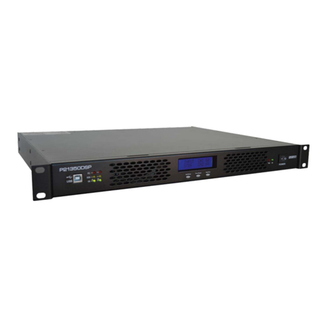
DEV 2182/50 User manual

User Manual
DEV 2182/zz (1:8)
DEV 2183/zz (2*1:8)
DEV 2185/zz (1:16)
(zz: impedance = 50 or 75 or 50-75 or 75-50)
L-Band Distribution Amplifiers
DEV Systemtechnik GmbH
Grüner Weg 4A
61169 Friedberg
GERMANY
Tel: +49 6031 6975 100
Fax: +49 6031 6975 114
support@dev-systemtechnik.com
www.dev-systemtechnik.com
Revision: 2017-06-27
DEV 91-0023-M

User Manual DEV 2182, DEV 2183, DEV 2185
2 Copyright DEV Systemtechnik GmbH 2003-2017
Table of Contents
1Revision History----------------------------------------------------------- 3
2Introduction---------------------------------------------------------------- 4
2.1 Warranty---------------------------------------------------------------------------------- 4
2.2 Limitation of Warranty---------------------------------------------------------------- 4
2.3 Warnings---------------------------------------------------------------------------------- 4
3Product Description ------------------------------------------------------ 6
3.1 Product Structure----------------------------------------------------------------------- 6
3.2 Device Panel ----------------------------------------------------------------------------- 8
3.2.1 Distribution Amplifier with Control Port ------------------------------------------ 8
3.2.2 Power Supply Monitoring ------------------------------------------------------------- 9
3.3 Product Drawings----------------------------------------------------------------------- 9
3.3.1 DEV 2182/50 ----------------------------------------------------------------------------- 9
3.3.2 DEV 2183/50-75----------------------------------------------------------------------- 10
3.3.3 DEV 2185/75 --------------------------------------------------------------------------- 11
4Installation Instructions------------------------------------------------12
4.1 Scope of Delivery --------------------------------------------------------------------- 12
4.2 Installation of the Product --------------------------------------------------------- 12
4.2.1 Mechanical Integration of the Product in a 19" Rack ------------------------ 12
4.2.2 Grounding, Alarm Cable, and Power Connection ----------------------------- 12
4.2.3 Connection of RF Signal Cables ---------------------------------------------------- 13
4.3 Device Factory Settings ------------------------------------------------------------- 13
4.4 Communication Interface Configuration --------------------------------------- 14
4.5 Setup via the Serial Interface------------------------------------------------------ 14
4.5.1 Start of the Configuration Program----------------------------------------------- 14
4.5.2 Operation of the Configuration Program---------------------------------------- 15
4.5.2.1 Configuration Program Commands --------------------------------------------------------- 15
4.5.2.2 Modification of the RF Threshold Level----------------------------------------------------16
4.5.2.3 Modification of the Current Monitoring Interval----------------------------------------17
4.6 Maintenance of the Product------------------------------------------------------- 17
5Operation of the Product ----------------------------------------------18
5.1 Operation via the Device Panel --------------------------------------------------- 18
6Error Indication-----------------------------------------------------------18
6.1 Error Indication via the Alarm Connector -------------------------------------- 18
6.1.1 A/B Alarm ------------------------------------------------------------------------------- 18
6.1.2 Amplifier Alarm------------------------------------------------------------------------ 18

User Manual DEV 2182, DEV 2183, DEV 2185
Copyright DEV Systemtechnik GmbH 2003-2017 3
7Connectors ----------------------------------------------------------------19
8Technical Data ------------------------------------------------------------19
9Conformance Declarations --------------------------------------------20
9.1 Certificate of Conformance -------------------------------------------------------- 20
9.2 EU Declaration of Conformity ----------------------------------------------------- 23
10 Glossary --------------------------------------------------------------------24
11 Notes------------------------------------------------------------------------24
1Revision History
Revision (Date)
Author
Short Description
A (27-Mar-2007)
WP
Recent version (introduced revision history)
B (28-Feb-2008)
WP
Revision to new document format
C (11-Jun-2008)
WP
Revised document format and minor corrections
D (04-Sep-2008)
WP
Minor corrections
E (18-Sep-2008)
WP
Minor corrections
F (17-Mar-2009)
WP
Minor corrections
G (28-Oct-2009)
WP
Supplementation of optical inputs devices
H (14-Apr-2010)
WP
Elimination of optical inputs devices
I (12-Oct-2010)
WP
Minor corrections
J (07-Jul-2011)
WP
New distribution amplifiers with serial interface
K (23-Jan-2014)
WP
Complete rework & integration of data sheet
L (12-Mar-2015)
WP
Documentation update
M (27-Jun-2017)
WP
Complete rework to new document format

User Manual DEV 2182, DEV 2183, DEV 2185
4 Copyright DEV Systemtechnik GmbH 2003-2017
2Introduction
Thank you for purchasing a DEV 218x/zz distribution amplifier. This user manual is
intended to familiarize you with the installation and operation of the device.
The DEV 218x/zz are a series of single or double 1:8 or 1:16 L-Band distribution
amplifiers (DAs) designed for professional use in ground stations and in cable TV
head end stations. The products are used to distribute small signals of the first
SAT/IF to satellite receivers or IRDs. All products are delivered in a rack mountable
1 RU chassis.
DEV Systemtechnik GmbH declares that this equipment meets all relevant
standards and rules. The unit carries a CE mark.
Please read all instructions before installation or usage of the product!
2.1 Warranty
The product has a warranty against defects in material and workmanship for a
period of two years from the date of shipment.
During the warranty period DEV Systemtechnik will, at its option, either repair or
replace the product if it turns out to be defective.
For warranty, service, or repair, the product must be returned to DEV System-
technik. The customer has to pay shipping charges to DEV Systemtechnik and
DEV Systemtechnik will pay shipping charges to return the product to the customer.
However, the customer is obliged to pay all duties, all taxes, and all other additional
costs arising from the shipment of the product.
DEV Systemtechnik warrants that the software and firmware designated by
DEV Systemtechnik for use with the product will execute its programming
instructions if installed properly. DEV Systemtechnik does not warrant that the
operation of the product, software, or firmware will be uninterrupted or error-free.
2.2 Limitation of Warranty
The preceding warranty does not apply to defects resulting from:
improper site preparation or site maintenance;
improper or inadequate interfacing of the product;
unauthorized modification or misuse of the product;
the application of software supplied by the customer;
improper or inadequate maintenance of the product;
operation beyond the environmental conditions specified for the product.
2.3 Warnings
The following safety measures must be observed during all phases of operation,
service, and repair of the device. Failure to comply with the safety precautions or
warnings in this document violates safety standards of design, manufacturing, and
intended use of the device and may affect the built-in protections. DEV System-
technik shall not be liable for the user's failure to comply with these requirements.
Disconnect the device from any external power line before opening of the housing.
In any case, the device is to be opened by trained service staff, only.

User Manual DEV 2182, DEV 2183, DEV 2185
Copyright DEV Systemtechnik GmbH 2003-2017 5
Environmental Conditions
The device is designed for indoor use and for an ambient temperature range.
Mechanical Integration
It is not permitted to fix the chassis on the rack mount flanges, only. Balanced
weight distribution of the chassis has to be ensured by placing it on a solid surface
or by using rack rails.
Sufficient airflow through the chassis must be ensured to achieve best cooling
results. Do not block or obstruct the airflow through the chassis at the front and at
the rear side, e.g. by placing large components close to the rear side.
Grounding, AC Connection, Cables
To minimize shock hazard the device must be connected to an electrical ground via
a ground wire, please refer to chapter 4.2.2. For the AC connection, the device
must be connected to the AC power supply mains through two power cables with
three conductors and with the ground wire firmly connected to an electrical ground
(safety ground) at the power outlet. Any interruption of the protective ground con-
ductor will cause a potential shock hazard that might cause personal injury.
Risk of electrical shock and energy hazard:
Disconnecting a single power supply line only does not interrupt the AC supply of
the device. To isolate the device completely, disconnect both power supply lines.
Do not connect the device to mains supply exceeding the specifications for input
voltage and frequency. The recommended AC cables to be applied are standard
high temperature power cables with type IEC 60320-C13 appliance plug appro-
priately rated to the conditions of the country where the device is operated.

User Manual DEV 2182, DEV 2183, DEV 2185
6 Copyright DEV Systemtechnik GmbH 2003-2017
3Product Description
There are available twelve different L-Band distribution amplifier products:
•DEV 2182/50: 1:8 Distribution Amplifier; 950…2150 MHz; 50 Ohm, SMA (f)
•DEV 2182/50-75: 1:8 Distribution Amplifier; 950…2150 MHz; 50 Ohm, SMA (f) - 75 Ohm, F (f)
•DEV 2182/75: 1:8 Distribution Amplifier; 950…2150 MHz; 75 Ohm, F (f)
•DEV 2182/75-50: 1:8 Distribution Amplifier; 950…2150 MHz; 75 Ohm, F (f) - 50 Ohm, SMA (f)
•DEV 2183/50: 2*1:8 Distribution Amplifier; 950…2150 MHz; 50 Ohm, SMA (f)
•DEV 2183/50-75: 2*1:8 Distribution Amplifier; 950…2150 MHz; 50 Ohm, SMA (f) - 75 Ohm, F (f)
•DEV 2183/75: 2*1:8 Distribution Amplifier; 950…2150 MHz; 75 Ohm, F (f)
•DEV 2183/75-50: 2*1:8 Distribution Amplifier; 950…2150 MHz; 75 Ohm, F (f) - 50 Ohm, SMA (f)
•DEV 2185/50: 1:16 Distribution Amplifier; 950…2150 MHz; 50 Ohm, SMA (f)
•DEV 2185/50-75: 1:16 Distribution Amplifier; 950…2150 MHz; 50 Ohm, SMA (f) - 75 Ohm, F (f)
•DEV 2185/75: 1:16 Distribution Amplifier; 950…2150 MHz; 75 Ohm, F (f)
•DEV 2185/75-50: 1:16 Distribution Amplifier; 950…2150 MHz; 75 Ohm, F (f) - 50 Ohm, SMA (f)
The DEV 2182/zz (DEV 2185/zz) is a distribution amplifier providing one input port
and eight (sixteen) output ports. The DEV 2183/zz is a dual distribution amplifier
with two input ports and two times eight output ports. The "zz" indicates that all
distribution amplifiers are available with 50 Ohm or 75 Ohm input ports and with
50 Ohm or 75 Ohm output ports. All 50 Ohm ports are realized with female SMA
connectors and for 75 Ohm ports female precision F connectors are applied.
All products provide redundant power supplies; and -for each channel- a moni-
toring output port, RF level monitoring functionality, and an LNB power supply with
current monitoring.
3.1 Product Structure
A distribution amplifier is designed as follows: The incoming signal is routed
through the LNB power supply to the connector labeled "Source" at the front side of
the chassis (please refer to the first illustration of chapter 3.2.1). The input
connector to the amplifier labeled "Amp In" is located there as well. A short external
cable bridge connects the (DC blocked) input signal routed through the LNB power
supply and the input to the amplifier. After the amplifier, the monitoring path is
coupled out (connector labeled "Monitor" at the front side) and the signal is split into
two outputs which can feed a 1:8 passive splitter, each. The second output is
terminated internally if it is not used (DEV 2182/zz, DEV 2183/zz).
The structure of the different products is shown in the block diagrams below.
LNB Power
DC
1:2 Splitter
Monitor
DC Block Am plifier RF-Sense
External Cable Bridge
DEV 73-0007
Output 8
Output 7
Output 6
Output 5
Output 4
Output 3
Output 2
Output 1
Input
1:8 Splitter
DEV 2182
Distribution Amplifier
Monitor
Am p In
Source
DC Block

User Manual DEV 2182, DEV 2183, DEV 2185
Copyright DEV Systemtechnik GmbH 2003-2017 7
Monitor
LNB Power
DC
1:2 Splitter
Monitor
DC Block Amplifier
Am p In
Source
RF-Sense
External Cable Bridge
DEV 73-0007
Output 1.8
Output 1.7
Output 1.6
Output 1.5
Output 1.4
Output 1.3
Output 1.2
Output 1.1
Input 1
1:8 Splitter
DEV 2183
DC
1:2 Splitter
Monitor
DC Block Amplifier RF-Sense
Output 2.8
Output 2.7
Output 2.6
Output 2.5
Output 2.4
Output 2.3
Output 2.2
Output 2.1
Input 2
1:8 Splitter
Distribution Am plifier 1
Distribution Am plifier 2
External Cable Bridge
DEV 73-0007
Monitor
Am p In
Source
LNB Power
DC Block
DC Block
LNB Power
DC
1:2 Splitter
Monitor
DC Block Amplifier RF-Sense
External Cable Bridge
DEV 73-0007
Output 8
Output 7
Output 6
Output 5
Output 4
Output 3
Output 2
Output 1
Input
DEV 2185
Output 16
Output 15
Output 14
Output 13
Output 12
Output 11
Output 10
Output 9
1:8 Splitter
1:8 Splitter
Distribution Amplifier
Monitor
Am p In
Source
DC Block
The front side of each product provides a device panel which is explained in
chapter 3.2. The power inlets, the alarm connector, and all other RF ports are
located at the rear side of the chassis (chapter 4.2.2). The front sides and the rear
sides are illustrated in a few product drawings (chapter 3.3).

User Manual DEV 2182, DEV 2183, DEV 2185
8 Copyright DEV Systemtechnik GmbH 2003-2017
3.2 Device Panel
3.2.1 Distribution Amplifier with Control Port
The products are equipped with one (DEV 2182, DEV 2185) or two (DEV 2183)
distribution amplifiers providing the following elements at the front side:
RF
LNB Power Source
Monitor Amp In
1 2 3 4 5 6
Usually (not shown in the figures) the distribution amplifier is operated with the
cable bridge DEV 73-0007 which is installed between the SMA ports labeled "Source"
((6), input signal routed through the LNB power supply) and "Amp In" ((2), input to
the amplifier). If the cable bridge is removed, this permits to directly access the
output of the inline amplifier or of the LNB connected to the input port of the
distribution amplifier (located at the rear side of the chassis) which is (or can be)
supplied by the LNB power supply of the distribution amplifier.
Additionally, an SMA port labeled "Monitor" (1) is available for signal monitoring,
providing an RF signal at the same level as the input signal.
The "LNB Power" push button (5) is used to turn on or to turn off the LNB power
supply. A ballpoint pen is recommended to operate the push button.
The LNB power status is indicated via the "LNB Power" LED (4): If the LNB power
supply is turned off, the LED is off. If the LNB power supply is turned on and if a
current is fed to the input of the distribution amplifier which is within a certain
adjustable range (i.e. the current monitoring interval), the LED is green. If the LED is
red, the current delivered by the LNB power supply is out of range, i.e. the red LED
signalizes an alarm which is indicated in parallel via potential free contacts at the
alarm connector (please refer to chapter 6.1.2).
With the RF level monitoring functionality of the distribution amplifier the
aggregated signal power level of the RF signal is measured and compared with an
RF threshold level. The status is signalized via the "RF" LED (3): Green means that
the signal level is above the threshold; red signalizes an alarm (i.e. the signal level is
below the threshold), which is indicated in parallel via potential free contacts at the
alarm connector (chapter 6.1.2).
Each distribution amplifier provides a control port realized as a serial interface
permitting the adjustment of the current monitoring interval and the adjustment of
the RF threshold level (chapter 4.5). The next figure shows the serial interface
connector (7) of a DEV 2182/zz or of a DEV 2185/zz:
Control
7

User Manual DEV 2182, DEV 2183, DEV 2185
Copyright DEV Systemtechnik GmbH 2003-2017 9
3.2.2 Power Supply Monitoring
Power Supply 1
Power Supply 2
Failure
8 9 10
Three LEDs located at the device panel on the right are signalizing the power supply
operating status of the device:
"Power Supply 1" LED ((8), green) and "Power Supply 2" LED ((9), green):
The related power supply unit provides secondary voltage if this LED is on.
"Failure" LED ((10), red): This LED is on if either power supply unit does not
deliver any secondary voltage. The reason for this can be a defective power
supply, a defective primary protection fuse, or a missing primary voltage.
3.3 Product Drawings
As stated above, there are available different versions of the L-Band distribution
amplifier products. Structural and from the layout, the different versions are very
similar. Therefore, only a selection of illustrations is shown next.
3.3.1 DEV 2182/50
Front View:
DEV 2182
L-Band Distribution A m plifie r 1:8
Pow er Supply 1
Pow er Supply 2
Failure
Con trol
RF
LN B P ower Source
Monitor Amp In
1 2 3 4 5 678 9 10
1
"Monitor" port; 50 Ohm, SMA (f)
2
"Amp In" input to amplifier; 50 Ohm, SMA (f)
3
"RF" LED for the RF level monitoring functionality
4
"LNB Power" LED for the LNB power status
5
"LNB Power" push button for operating the LNB power supply
6
"Source" input signal routed through the LNB power supply ; 50 Ohm, SMA (f)
7
"Control" connector for the serial interface ; Sub-D 9 (f)
8
Green LED indicating the operation of "Power Supply 1"
9
Green LED indicating the operation of "Power Supply 2"
10
Red LED indicating a "Failure" of one of the power supply units
Rear View:
50 ...60 H z
10 0 VA
10 0...240 V
Fuse 2 A T Fuse 2 A T
Alarm
Com mon
+15 V D C
1 2 345 6 7
910 11 12 13 14 15 16
8
WAR NIN G :
Discon nect po wer
be fore ope ning!
1 2 3 4 5 6 8
7
1
Grounding bolt
2
AC plug for power supply unit 1
3
Fuse for power supply unit 1
4
AC plug for power supply unit 2
5
Fuse for power supply unit 2
6
"Alarm" connector; Sub-D 9 (m)
7
"Common" input port; equipped with a 50 Ohm, SMA (f) connector; carrying DC current
8
Output ports labeled "1"…"8"; equipped with 50 Ohm, SMA (f) connectors; DC blocked

User Manual DEV 2182, DEV 2183, DEV 2185
10 Copyright DEV Systemtechnik GmbH 2003-2017
3.3.2 DEV 2183/50-75
Front View:
DEV 2183
L-Band D istrib ution A m p lifier 2 x 1:8
Pow er Supply 1
Pow er Supply 2
Failure
Con trol
Amplifier 2
RF
LN B P ower Source Am p 1Amp 2Monitor Amp In
Amplifier 1
RF
LN B P ower Source
Monitor Amp In
8 9 101.22.23.24.25.26.27.27.1
1.12.13.14.15.16.1
1.x
Distribution Amplifier x(x {1,2}): "Monitor" port; 50 Ohm, SMA (f)
2.x
Distribution Amplifier x(x {1,2}): "Amp In" input to amplifier; 50 Ohm, SMA (f)
3.x
Distribution Amplifier x(x {1,2}): "RF" LED for the RF level monitoring functionality
4.x
Distribution Amplifier x(x {1,2}): "LNB Power" LED for the LNB power status
5.x
Distribution Amplifier x(x {1,2}): "LNB Power" push button for operating the LNB power supply
6.x
Distribution Amplifier x(x {1,2}):
"Source" input signal routed through the LNB power supply ; 50 Ohm, SMA (f)
7.x
Distribution Amplifier x(x {1,2}): "Control" connector for the serial interface ; Sub-D 9 (f)
8
Green LED indicating the operation of "Power Supply 1"
9
Green LED indicating the operation of "Power Supply 2"
10
Red LED indicating a "Failure" of one of the power supply units
Rear View:
50 ...60 H z
10 0 VA
10 0...240 V
Fuse 2 A T Fuse 2 A T
Alarm
+15 V D C
WAR NIN G :
Discon nect po wer
be fore ope ning!
1.1 1.2 1 .3 1.4 1.5 1.6 1.7
2.1 2.2 2 .3 2.4 2.5 2.6 2.7 2.8
1.8
+15 V D C
1.Common 2.Common
1 2 3 4 5 67.17.28.28.1
1
Grounding bolt
2
AC plug for power supply unit 1
3
Fuse for power supply unit 1
4
AC plug for power supply unit 2
5
Fuse for power supply unit 2
6
"Alarm" connector; Sub-D 9 (m)
7.x
Distribution Amplifier x(x {1,2}):
"x.Common" input ports; equipped with 50 Ohm, SMA (f) connectors; carrying DC current
8.x
Distribution Amplifier x(x {1,2}):
Output ports labeled "x.1"…"x.8"; equipped with 75 Ohm, F (f) connectors; DC blocked

User Manual DEV 2182, DEV 2183, DEV 2185
Copyright DEV Systemtechnik GmbH 2003-2017 11
3.3.3 DEV 2185/75
Front View:
DEV 2185
L-Band Distribution A m plifie r 1:16
Pow er Supply 1
Pow er Supply 2
Failure
Con trol
RF
LN B P ower Source
Monitor Amp In
1 2 3 4 5 678 9 10
1
"Monitor" port; 50 Ohm, SMA (f)
2
"Amp In" input to amplifier; 50 Ohm, SMA (f)
3
"RF" LED for the RF level monitoring functionality
4
"LNB Power" LED for the LNB power status
5
"LNB Power" push button for operating the LNB power supply
6
"Source" input signal routed through the LNB power supply ; 50 Ohm, SMA (f)
7
"Control" connector for the serial interface ; Sub-D 9 (f)
8
Green LED indicating the operation of "Power Supply 1"
9
Green LED indicating the operation of "Power Supply 2"
10
Red LED indicating a "Failure" of one of the power supply units
Rear View:
50 ...60 H z
10 0 VA
10 0...240 V
Fuse 2 A T Fuse 2 A T
Alarm
Com mon
+15 V D C
1 2 345 6 7
910 11 12 13 14 15 16
8
WAR NIN G:
Disconnec t pow er
be fore ope ning!
1 2 3 4 5 6 8
7
1
Grounding bolt
2
AC plug for power supply unit 1
3
Fuse for power supply unit 1
4
AC plug for power supply unit 2
5
Fuse for power supply unit 2
6
"Alarm" connector; Sub-D 9 (m)
7
"Common" input port; equipped with a 75 Ohm, F (f) connector; carrying DC current
8
Output ports labeled "1"…"16"; equipped with 75 Ohm, F (f) connectors; DC blocked

User Manual DEV 2182, DEV 2183, DEV 2185
12 Copyright DEV Systemtechnik GmbH 2003-2017
4Installation Instructions
4.1 Scope of Delivery
1 * DEV 2182/zz, or DEV 2183/zz, or DEV 2185/zz equipped with
connectors (zz: 50, 50-75, 75, 75-50)
as ordered
1 * DEV 73-0007 cable bridge (DEV 2182/zz & DEV 2185/zz)
or
2 * DEV 73-0007 cable bridge (DEV 2183/zz)
1 * User Manual (this document)
4.2 Installation of the Product
4.2.1 Mechanical Integration of the Product in a 19" Rack
Please refer to the warnings in chapter 2.3 regarding the mechanical integration of
the product. For the integration in a 19" rack, the rack slots must be prepared with
rails for the chassis. After inserting the chassis in the rack, fix the chassis with four
screws to the rack at its rack mount flanges.
4.2.2 Grounding, Alarm Cable, and Power Connection
For the warnings with respect to "Grounding, AC Connection, Cables" please refer
to chapter 2.3.
The chassis needs to be connected to the 19" rack via a ground wire. The grounding
bolt is located on the left at the rear side of the product:
50...60 Hz
100 VA
100...240 V
Fuse 2 A T Fuse 2 A T
Alarm
WARNING:
Disconnect power
before opening!
1 2 3 4 5 6
Take off the upper nut and the first washer of the grounding bolt (labeled 1in the
figure above) and connect the grounding cable, which must have a ring tongue
terminal matching for the M4 fastening bolt. After that, the washer and the nut
have to be tightened again.
If required, connect the alarm cable to the alarm connector (6); the pin assignment
of the alarm connector is subject of chapter 7.
Finally, connect two power cords to the primary connectors (2& 4). It is recom-
mended to use two separately fused phases of the electrical outlets.
Note:
It is highly recommended to power up the device after the installation of all RF
signal cables (chapter 4.2.3)!
The power lines are fused separately; the fuse holders (3& 5) are located
below the related power inlet (2& 4). If a fuse has to be exchanged, unplug the
device completely and use 2 A T 5*20 mm glass fuses for replacement only!

User Manual DEV 2182, DEV 2183, DEV 2185
Copyright DEV Systemtechnik GmbH 2003-2017 13
4.2.3 Connection of RF Signal Cables
Apply strain relieves to the external RF signal cables which are to be connected in a
way, that the connectors of the device are not stressed mechanically.
If the DEV 218x is powered up already and before the RF cables are to be
connected to the chassis, the LNB power of the distribution amplifier(s) is to be
turned off! Otherwise there is a risk that a high impulse current degrades the RF
performance of the (corresponding) input connector.
The product is delivered with the DEV 73-0007 cable bridge(s) already installed. If
not installed, it is recommended to apply the cable bridge(s) first.
Then, connect the RF input cable(s) (e.g. from the LNB) to the related input port(s);
finally connect the RF output cables (to the signal receivers) to the output ports.
When connecting RF cables to the chassis, each connector is to be tightened with a
torque wrench. For 75 Ohm F connectors the applied torque should not exceed
4.5 Nm (39.8 lbf-in). In case of 50 Ohm SMA connectors, a torque wrench adjusted
to 1 Nm (8.85 lbf-in) is to be used.
Note:
For 75 Ohm RF connectors, female precision F connectors are applied. Make
sure, that the applied connectors are precision F connectors (with thin inner
conductor).
Each unused output port has to be terminated with an appropriate load to
achieve best amplitude frequency response.
Best signal quality is achieved by connecting the signal receivers symmetrically
to the output ports:
•1…4 and 5…8 of the (each) 1:8 splitter (DEV 2182/zz, DEV 2183/zz);
•1…4, 5…8, 9…12, and 13…16 of the 1:16 splitter (DEV 2185/zz);
and by connecting impedance matched loads to the unused ports.
If all cables are connected, the device can be powered up.
Now LNB power can be turned on for the distribution amplifier(s) which is (are)
required to feed power to an LNB.
4.3 Device Factory Settings
The distribution amplifiers provide RF level monitoring functionality, i.e. the
aggregated signal power level of the RF signal is measured and compared with an
RF threshold level. If the signal level is below the threshold level, an alarm is
triggered which is indicated via LED (please refer to chapter 3.2.1) and via the
alarm connector (chapter 6.1.2). The factory setting for the RF threshold level is:
RF Threshold Level: -40 dBm
The RF threshold level can be adjusted (chapter 4.5).
The distribution amplifiers are capable of providing LNB power at the RF input port.
With the current monitoring functionality, the delivered current is monitored. If the
measured current exceeds the defined interval, an alarm is generated indicated via
LED (chapter 3.2.1) and via alarm connector (chapter 6.1.2). The factory settings for
the current monitoring interval are:
Lower Limit: 100 mA
Upper Limit: 350 mA
The lower limit and the upper limit of the current monitoring interval can be
adjusted (chapter 4.5).

User Manual DEV 2182, DEV 2183, DEV 2185
14 Copyright DEV Systemtechnik GmbH 2003-2017
4.4 Communication Interface Configuration
Per distribution amplifier a serial interface is provided as the communication
interface. The serial interface -requiring a standard terminal application, only- is
used for the setup of the RF threshold level and for the setup of the current
monitoring interval.
The Sub-D 9 pos female connector(s) labeled "Control" for the standard (3 wire)
RS 232 interface(s) is (are) located at the device panel (please refer to chapter
3.2.1); the pin assignment is stated in chapter 7.
The serial interface configuration is described by the following parameters:
Transmission rate: 9600
Data bits: 8
Parity check: none
Start/Stop bit: 1
Handshake: none
4.5 Setup via the Serial Interface
4.5.1 Start of the Configuration Program
To access the configuration program of a distribution amplifier, establish a hard-
ware connection between a serial port of a PC (e.g. COM1) and the (corresponding)
"Control" connector at the device panel using a straight cable; please refer to
chapter 7 for the pin assignment of the serial connector.
Next, start a terminal application (e.g. MS Windows HyperTerminal) on your PC.
If the terminal application was started and connected before the device was
powered up, the start-up info is displayed:
42-0230 ** Sat ZF Amplifier
B.01 ** Jun 29 2011 13:54:37
System Values lowlim meas. highlim
Bias on [mA]: 150.0 173.1 350.0
RFSense [dB]: -40.0 -24.7
press '?' for help
>
Depending on the type of the installed distribution amplifier, the identification
string (42-0230 ** Sat ZF Amplifier) and the firmware revision and date string
(B.01 ** Jun 29 2011 13:54:37) in the start-up info may vary.
The table below the identification string and the firmware revision and date string
consists of three lines only; in the example above the status and the measurement
of the "System Values" (Bias (LNB power supply) and RFSense (RF level) in the first
column) are shown. Note, that here Bias on is displayed here, since the LNB power
supply is turned on, otherwise Bias off appears instead. The second column
"lowlim" shows the applied lower limit for the current monitoring interval (here:
150.0 mA) and the applied RF threshold level (here: -40.0 dBm). The third column
"meas." shows the measured values for the current monitoring (here: 173.1 mA)
and for the RF level (here: -24.7 dBm). The forth column "highlim" shows the
applied upper limit for the current monitoring interval (here: 350.0 mA), only.
Note:
The interface settings of the terminal application have to match the serial
interface settings as described in chapter 4.4, otherwise it is not possible to
communicate with the configuration program.

User Manual DEV 2182, DEV 2183, DEV 2185
Copyright DEV Systemtechnik GmbH 2003-2017 15
The start-up info is not displayed if the terminal application was started and
connected after the device was powered up. Hitting any key on the keyboard
should cause a response of the configuration program followed by a prompt
character (">") indicating that the configuration program is ready for executing
the next command or input.
If there is no prompt visible or no response to an input, please check the serial
interface connection and the settings of the terminal application.
Valid commands or inputs for the configuration program are not echoed.
In this context and for better comprehension, commands or inputs are
indicated via bold courier letters.
4.5.2 Operation of the Configuration Program
In the following, the commands are presented which can be executed with the
configuration program.
4.5.2.1 Configuration Program Commands
Typing the question mark character ("?") lists the available commands:
>?
?: this help
select limit input for
r: RF Sense
b: Bias low
B: Bias high
s: save
q: quit without saving
d: display values
>
"?": output of the help text above;
"r": command for the modification of the RF threshold level
(please refer to chapter 4.5.2.2);
"b": command for the modification of the lower limit of the current monitoring
interval (chapter 4.5.2.3);
"B": command for the modification of the upper limit of the current monitoring
interval (chapter 4.5.2.3);
"s": command for applying and storing the changes made for the RF threshold level
setting and/or for the current monitoring interval settings;
"q": command for discarding changes made for the RF threshold level setting and/or
for the current monitoring interval settings (i.e. the values of the last "s"
command are still valid);
"d": monitoring command which returns the table informing about the current
settings and the measured values (equivalent to the table of the start-up info as
stated in chapter 4.5.1), e.g.
System Values lowlim meas. highlim
Bias on [mA]: 150.0 173.8 350.0
RFSense [dB]: -40.0 -24.5
>
Note:
The commands or inputs for the configuration program are not case sensitive,
except for "b" and "B".
Typing of a character (e.g. "i") which is not a valid command results in:
>i?
>

User Manual DEV 2182, DEV 2183, DEV 2185
16 Copyright DEV Systemtechnik GmbH 2003-2017
4.5.2.2 Modification of the RF Threshold Level
The modification of the RF threshold level is performed in two steps.
After the "r" command was entered, the configuration program responds:
>r
change RF Low Limit via "p"lus or "m"inus
>
By entering the (lower case) "p" (or the (capital) "P" or the "+") character, the value
is increased in steps of 1.0 dB:
>p-39.0
>+-38.0
>P-37.0
>
Or, by entering the (lower case) "m" (or the (capital) "M" or the "-") character, the
value is decreased in steps of 1.0 dB:
>m-38.0
>M-39.0
>--40.0
>
The second step is to store the value(s) by issuing the "s" command, which is
responded by the configuration program with:
>svalues saved
>
If changes on the value(s) are not to be saved and for retrieving the saved settings,
the "q" command is to be entered instead, which results in the response:
>qdiscarding input
>
Note:
It is possible, to alter more than one setting (i.e. the RF threshold level plus one
or both limits of the current monitoring interval) before saving or discarding
the changes.
Inputs to the configuration program are not echoed, only here they are
indicated for better comprehension.

User Manual DEV 2182, DEV 2183, DEV 2185
Copyright DEV Systemtechnik GmbH 2003-2017 17
4.5.2.3 Modification of the Current Monitoring Interval
The modification of the lower limit or of the upper limit of the current monitoring
interval is performed in two steps.
After the (lower case) "b" command (for the lower limit) was entered, the
configuration program responds:
>b
change Bias Low Limit via +/-
>
Or, to change the upper limit, enter the (capital) "B" command which returns:
>B
change Bias High Limit via +/-
>
In both cases, by entering the "+" (or the (lower case) "p" or the (capital) "P")
character, the value is increased in steps of 10.0 mA:
>+360.0
>p370.0
>P380.0
>
Or, by entering the "-" (or the (lower case) "m" or the (capital) "M") character, the
value is decreased in steps of 10.0 mA:
>-370.0
>M360.0
>m350.0
>
The second step is to store the value(s) by issuing the "s" command, which is
responded by the configuration program with:
>svalues saved
>
If changes on the value(s) are not to be saved and for retrieving the saved settings,
the "q" command is to be entered instead, which results in the response:
>qdiscarding input
>
Note:
It is possible, to alter more than one setting (i.e. one or both limits of the
current monitoring interval plus the RF threshold level) before saving or dis-
carding the changes.
It is recommended to select both limits of the current monitoring interval in a
way, that their values are not too close to the nominal current consumption of
the sink(s) to avoid frequent alarms due to variations in the current consump-
tion of the sink and due to the measurement accuracy of the distribution
amplifier.
Again, inputs to the configuration program are not echoed, only here they are
indicated for better comprehension.
4.6 Maintenance of the Product
The product is maintenance-free.
Cleaning of the surface of the chassis should be done carefully with a dry lint-free
cloth.

User Manual DEV 2182, DEV 2183, DEV 2185
18 Copyright DEV Systemtechnik GmbH 2003-2017
5Operation of the Product
After going through the installation steps, the device is ready to use.
5.1 Operation via the Device Panel
Beside the "LNB Power" push button(s) (please refer to chapter 3.2.1), there is (are)
no element(s) to be operated. The operating status of the device is indicated via
LEDs which were already described in chapter 3.2 as well.
And chapter 4.5 explains the setup of the RF threshold level and of the current
monitoring interval via the serial interface.
6Error Indication
The indication of an error (i.e. an alarm) is realized via hardware, i.e. via red LEDs
(please refer to chapter 3.2) and via the alarm connector.
6.1 Error Indication via the Alarm Connector
The potential free contacts of the alarm connector located at the rear side provide
the following functionality (for the pin assignment, please refer to chapter 7):
6.1.1 A/B Alarm
A/B-Alarm signalizes that one or all power supplies do not deliver secondary power.
B-Alarm signalizes that one power supply unit does not deliver secondary power,
and A-Alarm signalizes that no power supply delivers secondary power.
nc–common
no-common
State:
Closed
Open
Normal
Closed
Closed
B –Alarm
Open
Closed
A –Alarm
Open
Open
Not possible
6.1.2 Amplifier Alarm
The amplifier alarm is available (once or twice) at the alarm connector for remote
detection. The amplifier alarm indicates:
that the RF signal level was detected to be below the RF threshold level; or
that the current delivered by the LNB power supply was detected not to be
within the current monitoring interval; or
that both alarms are active (logical OR).
Note, that the amplifier alarm is active as well if the amplifier is not supplied with
power, i.e. either due to a power supply fail or if the device is powered off.
nc–common
no-common
State:
Closed
Open
Normal
Closed
Closed
Not possible
Open
Closed
Alarm or
Power off
Open
Open
Not possible
normally open no
common
normally closed nc
(No Alarm)
PIN 7 nc
PIN 9 no
PIN 8 common
(No A/B-Alarm)

User Manual DEV 2182, DEV 2183, DEV 2185
Copyright DEV Systemtechnik GmbH 2003-2017 19
7Connectors
AC Power Plug
Connector: IEC rubber connector (male) IEC 60320 C14
Connector screws: none
AC Power Plug
Pin
Functionality
Pin 1
L (Live/Phase)
Pin 2
PE (Protective Earth)
Pin 3
N (Neutral)
Serial Connector
Connector: Sub-D 9 (female)
Connector screws: UNC 4-40
Serial Connector (RS 232)
Pin
Functionality
Pin 1
do not use
Pin 2
Tx
Pin 3
Rx
Pin 4
do not use
Pin 5
GND
Pins 6…9
do not use
"do not use" means that normally the pin should be left open. It is usually not a problem to use a fully
populated 1:1 Sub-D 9 (m)-(f) cable to establish a RS 232 connection between the device and a PC.
Alarm Connector
Connector: Sub-D 9 (male)
Connector screws: UNC 4-40
Alarm Connector
Pin
Functionality
DEV 2183/zz
DEV 2182/zz, DEV 2185zz
Pin 1
Amplifier 1 Alarm normally closed
Amplifier Alarm normally closed
Pin 2
Amplifier 1 Alarm Common pin
Amplifier Alarm Common pin
Pin 3
Amplifier 1 Alarm normally open
Amplifier Alarm normally open
Pin 4
Amplifier 2 Alarm normally closed
do not use
Pin 5
Amplifier 2 Alarm Common pin
do not use
Pin 6
Amplifier 2 Alarm normally open
do not use
Pin 7
A/B Alarm normally closed
Pin 8
A/B Alarm Common pin
Pin 9
A/B Alarm normally open
•"normally closed" means, that the pin is connected to its common pin if no alarm is pending.
•"normally open" means, that the pin is not connected to its common pin if no alarm is pending.
•"do not use" means that normally the pin should be left open.
8Technical Data
The technical data is stated in the spec sheet; please refer to
www.dev-systemtechnik.com.
123
9
1
9
1

User Manual DEV 2182, DEV 2183, DEV 2185
20 Copyright DEV Systemtechnik GmbH 2003-2017
9Conformance Declarations
9.1 Certificate of Conformance
Since DEV Systemtechnik develops and produces in Germany, the Certificate of
Conformance for each product or product series is to be issued in German
(as stated on the next page).
For the ease of comprehension the harmonized standards which were taken into
consideration during development and production are listed here in English:
DIN EN 50083-2:2016-03 Cable networks for television signals, sound signals and interactive services -
Part 2: Electromagnetic compatibility for equipment;
German version EN 50083-2:2012 + A1:2015
DIN EN 55022:2011-12 Information technology equipment - Radio disturbance characteristics -
Limits and methods of measurement
(CISPR 22:2008, modified); German version EN 55022:2010
DIN EN 55024:2016-05 Information technology equipment - Immunity characteristics -
Limits and methods of measurement
(CISPR 24:2010 + Cor.:2011 + A1:2015); German version EN 55024:2010 + A1:2015
DIN EN 61000-3-2:2015-03 Electromagnetic compatibility (EMC) - Part 3-2: Limits -
Limits for harmonic current emissions (equipment input current ≤ 16 A per phase)
(IEC 61000-3-2:2014); German version EN 61000-3-2:2014
DIN EN 61000-3-3:2014-03 Electromagnetic compatibility (EMC) - Part 3-3: Limits -
Limitation of voltage changes, voltage fluctuations, and flicker in public low-voltage
supply systems, for equipment with rated current ≤16 A per phase and not subject to
conditional connection
(IEC 61000-3-3:2013); German version EN 61000-3-3:2013
DIN EN 62368-1:2016-05 Audio/video, information and communication technology equipment -
Part 1: Safety requirements
(IEC 62368-1:2014, modified + Cor.:2015);
German version EN 62368-1:2014 + AC:2015
This manual suits for next models
14
Table of contents
Other DEV Amplifier manuals
