3
2.0 OPERATION
NOTE: Installations above 6000 feet, 1825 meters
Unit is adjusted to operate in altitudes up to 6000 feet,
1825 meters. If unit is installed in an altitude above this,
and has not been preset at the factory for this altitude,
contact Manufacturer’s Service Department.
2.1 Start-up
Start refrigeration system by pushing the on/off switch to
the ON position (depress rocker switch on side marked
“I”).
NOTE: The fault light may illuminate when unit is ener-
gized. Light should go out approximately 5 minutes
after start-up. If light remains lit after 30 minutes or
illuminates after going out, refer to Troubleshooting
Guide.
2.2 Operating check points
Check the following on a periodic basis:
A. Rocker switch is in the ON position.
B. Amber fault light is out.
C. Condensate is being regularly discharged.
2.3 Minimum/maximum operating conditions
A. Minimum/Maximum air pressure: 20/175 psig,
1.4/12.3 kgf/cm 2
B. Maximum inlet air temperature: 180 °F, 82°C
C. Minimum/Maximum ambient temperature:
35/110°F, 2/43 °C
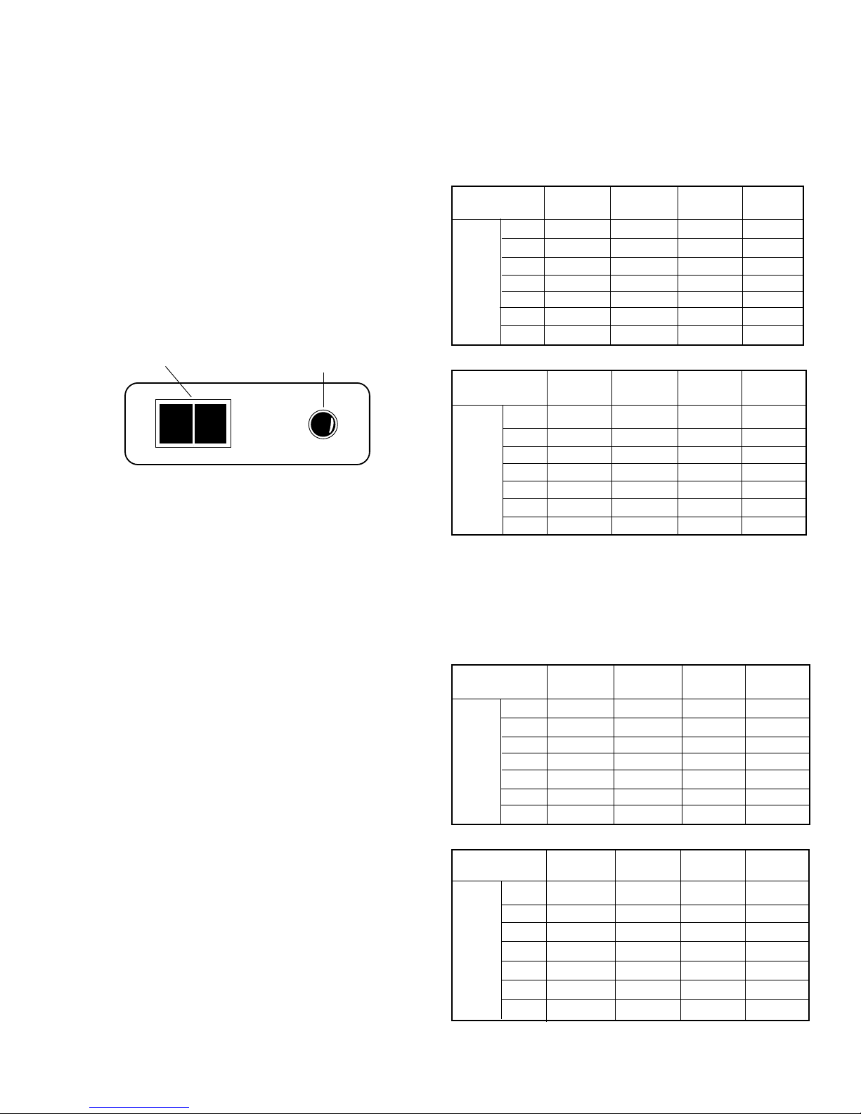
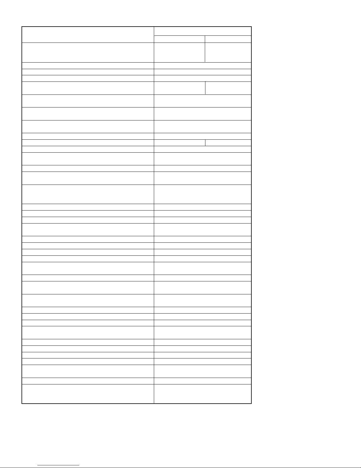
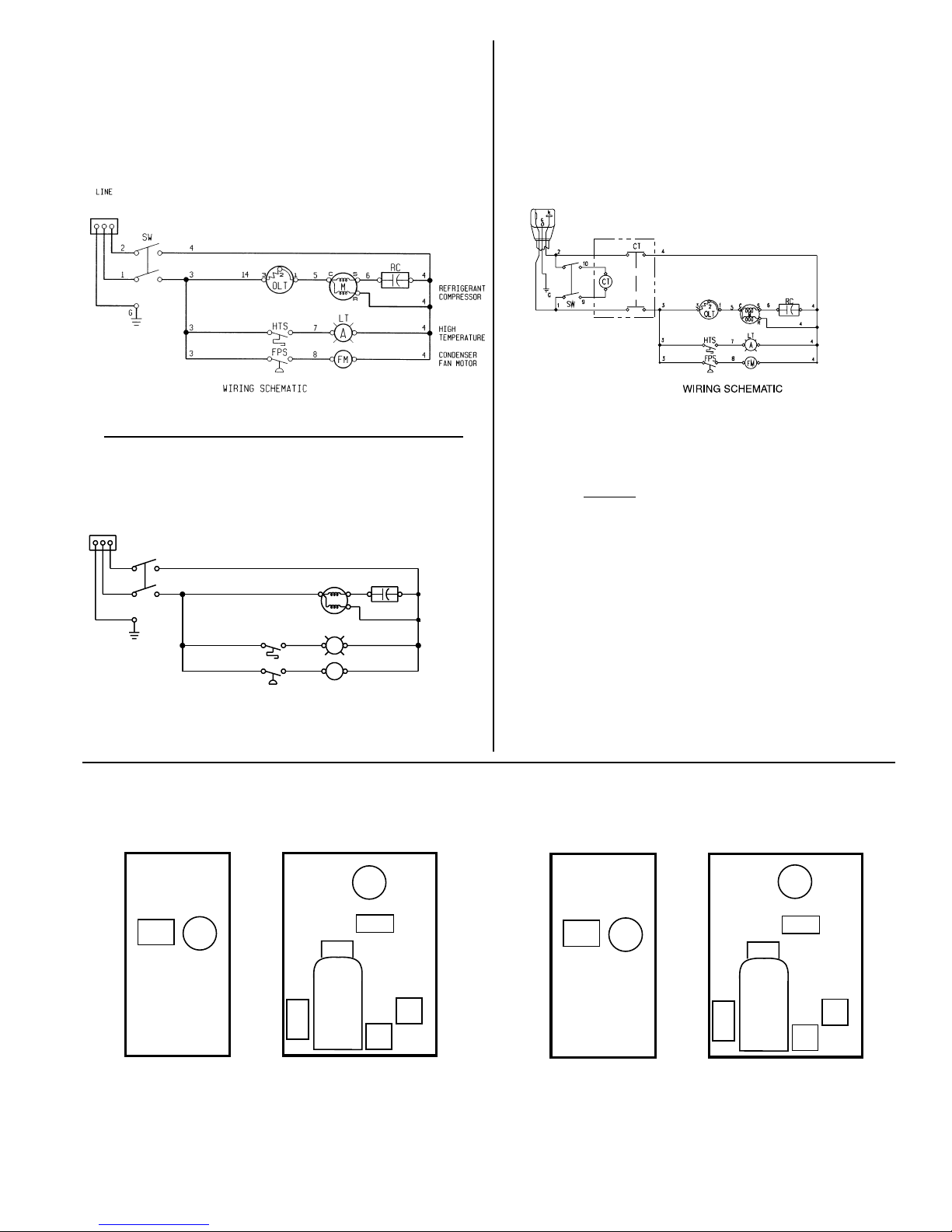
Control Panel
I
O
On/Off Switch Fault Light
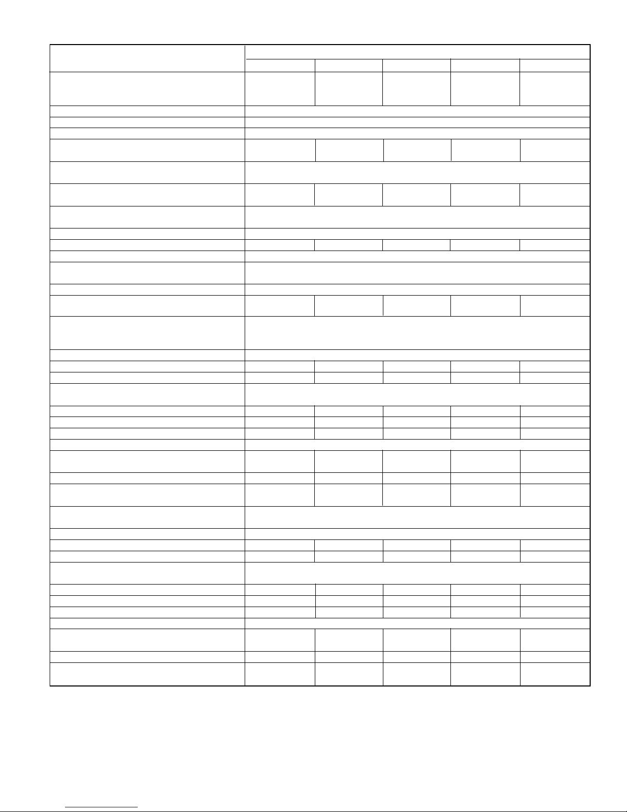
2. For dryers with an aftercooler installed upstream
Flow capacity in scfm (m 3/min) @ 100 °F, 38°C inlet
temperature, 100 °F, 38°C inlet pressure dew point,
100°F, 38°C ambient temperature, 50 °F, 10°C outlet
pressure dew point, and less than 10 psi, 0.7 kgf/cm 2
pressure drop.
175 (12.3) 150 (10.6) 125 (8.8) 100 (7.0)
20 23 (0.65) 22 (0.62) 20 (0.57) 18 (0.51)
25 29 (0.82) 27 (0.76) 25 (0.71) 23 (0.65)
35 41 (1.16) 38 (1.08) 35 (0.99) 32 (0.91)
Model 50 58 (1.64) 54 (1.53) 50 (1.42) 45 (1.27)
75 87 (2.46) 81 (2.29) 75 (2.12) 68 (1.93)
100 116 (3.29) 108 (3.06) 100 (2.83) 91 (2.58)
125 145 (4.12) 135 (3.82) 125 (3.54) 114 (3.23)
D. Maximum flow capacity
1. For dryers without an aftercooler installed upstream
Flow capacity in scfm (m 3/min) @ 180 °F, 82°C inlet
temperature, 160 °F, 71°C inlet pressure dew point,
95°F, 35°C ambient temperature, 50 °F, 10°C outlet
pressure dew point, and less than 5 psi, 0.35 kgf/cm 2
pressure drop.
175 (12.3) 150 (10.6) 125 (8.8) 100 (7.0)
20 20 (0.57) 18 (0.51) 17 (0.48) 15 (0.42)
25 24 (0.68) 23 (0.65) 21 (0.59) 19 (0.54)
35 31 (0.88) 29 (0.82) 27 (0.76) 24 (0.68)
Model 50 58 (1.64) 54 (1.53) 50 (1.42) 45 (1.27)
75 71 (2.01) 66 (1.87) 61 (1.73) 55 (1.56)
100 97 (2.75) 90 (2.55) 83 (2.35) 76 (2.15)
125 121 (3.43) 112 (3.17) 104 (2.95) 95 (2.69)
50 HZ
60 HZ
60 HZ
50 HZ
Inlet Pressure
psig (kgf/cm2)
Inlet Pressure
psig (kgf/cm2)
175 (12.3) 150 (10.6) 125 (8.8) 100 (7.0)
20 32 (0.91) 30 (0.85) 28 (0.79) 25 (0.71)
25 40 (1.13) 37 (1.05) 34 (0.96) 31 (0.88)
35 55 (1.56) 51 (1.44) 47 (1.33) 43 (1.22)
Model 50 78 (2.21) 73 (2.07) 67 (1.90) 61 (1.73)
75 118 (3.34) 110 (3.12) 102 (2.89) 92 (2.61)
100 157 (4.45) 146 (4.14) 136 (3.85) 123 (3.48)
125 197 (5.58) 183 (5.18) 170 (4.82) 155 (4.39)
Inlet Pressure
psig (kgf/cm2)
175 (12.3) 150 (10.6) 125 (8.8) 100 (7.0)
20 27 (0.76) 25 (0.71) 23 (0.65) 21 (0.59)
25 33 (0.93) 31 (0.88) 29 (0.82) 26 (0.74)
Model 35 43 (1.22) 40 (1.13) 37 (1.05) 33 (0.93)
50 78 (2.21) 73 (2.07) 67 (1.90) 61 (1.73)
75 96 (2.72) 90 (2.55) 83 (2.35) 75 (2.12)
100 131 (3.71) 122 (3.46) 113 (3.20) 102 (2.89)
125 164 (4.65) 152 (4.31) 142 (4.02) 129 (3.65)
Inlet Pressure
psig (kgf/cm2)