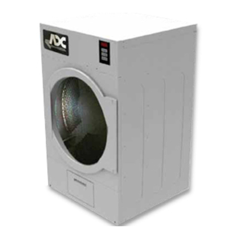
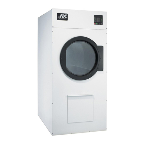
ADC AD-75V User manual

012000MS/tcosta ADCPartNo.113124
For replacement parts, contact the reseller from which the dryer
was purchased or
AmericanDryerCorporation
88Currant Road
FallRiverMA02720-4781
Telephone:(508) 678-9000 / Fax: (508)678-9447
e-mail:techsupport@amdry.com
www.amdry.com
AD-75V
(Gas DSI/Electric/Steam)
Installation Manual
WARNING: Foryoursafetytheinformationin
thismanual mustbe followedto minimizethe
riskof fireor explosionor toprevent property
damage,personalinjury or death.
— Donot storeoruse gasolineor other flammable
vapors and liquids in the vicinity of this or any
otherappliance.
— WHATTODO IFYOUSMELLGAS:
• Donottryto lightany appliance.
• Donottouch anyelectrical switch;donot
useanyphoneinyourbuilding.
• Cleartheroom, buildingor areaof all
occupants.
• Immediatelycallyourgassupplierfroma
neighbor’sphone. Followthe gassupplier’s
instructions.
• Ifyoucannotreach yourgas supplier,call
thefiredepartment.
— Installationand servicemustbe performedby a
qualified installer, service agency or the gas
supplier.
AVERTISSEMENT: Assurez-vous de bien
suivrelesinstructionsdonnéesdanscettenotice
pourréduire auminimumle risqued’incendie
ou d’explosion ou pour éviter tout dommage
matériel,touteblessureou lamort.
— Ne pas entreposer ni utiliser d’essence ni
d’autres vapeurs ou liquides inflammables à
proximité de cet appareil ou de tout autre
appareil.
— QUEFAIRESIVOUSSENTEZUNEODEUR
DEGAZ:
• Nepastenter d’allumerd’appareils.
• Netouchez àaucun interrupteur. Nepas
vousservirdes téléphonessetrouvant dans
lebâtiment.
• Évacuezlapièce,le bâtimentou lazone.
• Appelezimmédiatementvotrefournisseur
degazdepuisunvoisin. Suivez les
instructionsdufournisseur.
• Sivousnepouvezrejoindrelefournisseur
degaz,appelez leservicedes incendies.
— L’installationetl’entretiendoiventêtreassuréspar
uninstallateurou unservice d’entretienqualifié
ouparle fournisseurdegaz.
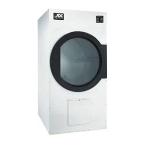
Retain This Manual In ASafe Place For Future Reference
American Dryer Corporation products embody advanced concepts in engineering, design, and safety. If this product is
properly maintained, it will provide many years of safe, efficient, and trouble free operation.
ONLY qualified technicians should service this equipment.
OBSERVE ALL SAFETY PRECAUTIONS displayed on the equipment or specified in the installation manual included with
the dryer.
The following “FOR YOUR SAFETY” caution must be posted near the dryer in a prominent location.
“IMPORTANTNOTETOPURCHASER”
Informationmustbeobtainedfromyourlocalgassupplierontheinstructions
tobefollowed iftheusersmells gas. Theseinstructionsmustbeposted ina
prominentlocationnearthedryer.
FORYOUR SAFETY
Donot storeor usegasoline or
otherflammablevaporsand
liquidsinthevicinityofthisor
anyotherappliance.
POURVOTRESÉCURITÉ
Nepas entreposer niutiliserd’essence
nid’autresvapeursouliquides
inflammablesàproximitédecet
appareilou detoutautre appareil.
We have tried to make this manual as complete as possible and hope you will find it useful. ADC reserves the right to make
changes from time to time, without notice or obligation, in prices, specifications, colors, and material, and to change or
discontinue models. The illustrations included in this manual may not depict your particular dryer exactly.
Important
For your convenience, log the following information:
DATE OFPURCHASE________________________________ MODELNO. __________________________________________
RESELLER’SNAME ________________________________________________________________________________________
Serial Number(s) ________________________________________________________________________________________
________________________________________________________________________________________
________________________________________________________________________________________
Replacement parts can be obtained from your reseller or the ADCfactory. Whenordering replacementparts from the factory,
you can FAX your order to ADC at (508) 678-9447 or telephone your order directly to the ADC Parts Department at (508)
678-9000. Please specify the dryer modelnumber andserialnumberin addition to the descriptionand partnumber, so that
your order is processed accurately and promptly.
AD-75V

WARNING
UNDER NO CIRCUMSTANCES should the dryer door switches, lint drawer switch,
or the heat safety circuit ever be disabled.
IMPORTANT
YOUMUSTDISCONNECTANDLOCKOUTTHEELECTRICSUPPLYANDTHEGAS
SUPPLY OR THE STEAM SUPPLY BEFORE ANY COVERS OR GUARDS ARE
REMOVED FROM THE MACHINE TO ALLOW ACCESS FOR CLEANING,
ADJUSTING, INSTALLATION, OR TESTING OF ANY EQUIPMENT PER OSHA
(OccupationalSafetyand HealthAdministration)STANDARDS.
WARNING
CHILDRENSHOULD NOTBEALLOWEDTOPLAYONORNEARTHEDRYER(S).
CHILDRENSHOULDBESUPERVISEDIFNEARDRYERSINOPERATION.
CAUTION
DRYERSSHOULDNEVERBELEFTUNATTENDEDWHILEINOPERATION.
FORYOURSAFETY
DONOTDRYMOPHEADSINTHEDRYER.
DONOTUSEDRYERINTHEPRESENCEOFDRYCLEANINGFUMES.
“Caution: Label all wires prior to
disconnection when servicing controls. Wiring
errors can cause improper operation.”
«Attention: Au moment de l’entretien des
commandes,étiqueteztous les filsavantde
les débrancher. Des erreurs de câblage
peuvent entraîner un fonctionnement
inadéquatetdangereux.»

WARNING
The dryer must never be operated with any of the back guards, outer tops, or service
panelsremoved. PERSONALINJURYORFIRECOULDRESULT.
IMPORTANT
PLEASEOBSERVEALLSAFETYPRECAUTIONSdisplayedontheequipmentand/or
specified in the installation manual included with the dryer.
WARNING
DRYERMUSTNEVERBEOPERATEDWITHOUTTHELINTFILTER/SCREENIN
PLACE,EVENIFANEXTERNALLINTCOLLECTIONSYSTEMISUSED.
Dryer mustnotbe installed or stored in an area where it willbe exposed to water or weather.
The wiring diagram for the dryer is located in the front electrical control box area.
IMPORTANT
Dryer must be installed in a location/environment, which the ambient temperature
remains between 40° F (4.44° C) and 130° F (54.44° C).

Table of Contents
SECTION I
IMPORTANT INFORMATION ...............................................................................3
A. ReceivingandHandling ............................................................................................................... 3
B. SafetyPrecautions ...................................................................................................................... 4
SECTION II
SPECIFICATIONS.....................................................................................................6
A. Specifications ............................................................................................................................. 6
SECTION III
INSTALLATION PROCEDURES ...........................................................................8
A. Unpacking/SettingUp ................................................................................................................. 8
B. LocationRequirements ............................................................................................................... 9
C. DryerEnclosureRequirements .................................................................................................. 10
D. FreshAirSupplyRequirements ................................................................................................. 11
E. ExhaustRequirements ............................................................................................................... 12
F. ElectricalInformation ................................................................................................................ 18
G. GasInformation ........................................................................................................................ 25
H. SteamInformation .................................................................................................................... 29
I. PreparationFor Operation/Start-Up ......................................................................................... 34
J. PreoperationalTests ................................................................................................................. 35
K. PreoperationalInstructions ........................................................................................................ 36
L. ShutdownInstructions............................................................................................................... 39
SECTION IV
SERVICE/PARTS INFORMATION ......................................................................40
A. Service ..................................................................................................................................... 40
B. Parts ........................................................................................................................................ 40
SECTION V
WARRANTY INFORMATION...............................................................................41
A. ReturningWarrantyCards......................................................................................................... 41
B. Warranty .................................................................................................................................. 41
C. ReturningWarrantyParts .......................................................................................................... 41

SECTION VI
ROUTINE MAINTENANCE ..................................................................................43
A. Cleaning ................................................................................................................................... 43
B. Adjustments ............................................................................................................................. 44
C. Lubrication ............................................................................................................................... 44
D. LintDrawerRemoval................................................................................................................ 45
SECTION VII
TROUBLESHOOTING ...........................................................................................46
MicroprocessorController(Computer) Models .............................................................................. 46
DualTimerModels ......................................................................................................................... 52
SECTION VIII
DATA LABEL INFORMATION .............................................................................56
A. DataLabel ............................................................................................................................... 56
SECTION IX
REVERSING TIMER SPIN/DWELL ADJUSTMENTS.....................................58
SECTION X
PROCEDURE FOR FUNCTIONAL CHECK OF REPLACEMENT
COMPONENTS........................................................................................................59
SECTION XI
BURNER AND LINT BASKET (TUMBLER) CHAMBER MANUAL RESET
HI-LIMIT INSTRUCTIONS ...................................................................................62
GasModelsOnly ........................................................................................................................... 62
ElectricorSteam Models................................................................................................................ 63

3
SECTIONI
IMPORTANTINFORMATION
A. RECEIVINGAND HANDLING
The dryer is shipped in a protective stretch wrap cover with protective cardboard corners and top cover (or
optional box) as a means of preventing damage in transit. Upon delivery, the dryer and packaging, and wooden
skid should be visually inspected for shipping damage. If any damage whatsoever is noticed, inspect further
before delivering carrier leaves.
Dryers damaged in shipment:
1. ALL dryers should be inspected upon receipt and before they are signed for.
2. If there is suspected damage or actual damage, the trucker’s receipt should be so noted.
3. If the dryer is damaged beyond repair, it should be refused. Those dryers which were not damaged in a
damaged shipment should be accepted, but the number received and the number refused must be noted
on the receipt.
4. If you determine that the dryer was damaged after the trucker has left your location, you should call the
delivering carrier’s freight terminal immediately and file a claim. The freight company considers this
concealed damage. This type of freight claim is very difficult to get paid and becomes extremely difficult
when more than a day or two passes after the freight was delivered. It is your responsibility to file freight
claims. Dryer/parts damaged in transit cannot be claimed under warranty.
5. Freight claims are the responsibility of the consignee, andALL claims must be filed at the receiving end.
ADC assumes no responsibility for freight claims or damages.
6. If you need assistance in handling the situation, please contact the ADC Traffic Manager at (508)
678-9000.
IMPORTANT: Thedryermustbetransportedand handledinanupright positionatALLtimes.

4
B. SAFETY PRECAUTIONS
WARNING: Foryoursafety,theinformationinthis manualmustbefollowed tominimizetheriskof
fireorexplosion ortopreventproperty damage,personalinjury,or lossof life.
WARNING: The dryermustnever be operatedwith any oftheback guards,outertops, or
servicepanelsremoved. PERSONALINJURYOR FIRE COULDRESULT.
1. DO NOT store or use gasoline or other flammable vapors and liquids in the vicinity of this or any other
appliance.
2. Purchaser/user should consult the local gas supplier for proper instructions to be followed in the event the
user smells gas. The instructions should be posted in a prominent location.
3. WHAT TO DO IF YOU SMELL GAS...
a. DO NOT try to light any appliance.
b. DO NOT touch any electrical switch.
c. DO NOT use any phone in your building.
d. Clear the room, building, or area of ALLoccupants.
e. Immediately call your gas supplier from a neighbor’s phone. Follow the gas supplier’s instructions.
f. If you cannot reach your gas supplier, call the fire department.
4. Installation and service must be performed by a qualified installer, service agency, or gas supplier.
5. Dryer(s) must be exhausted to the outdoors.
6. Although ADC produces a very versatile dryer, there are some articles that, due to fabric composition or
cleaning method, should not be dried in it.
WARNING: Dry onlywater washedfabrics. DO NOTdry articlesspotted orwashed indry
cleaningsolvents,acombustibledetergent,or“allpurpose”cleaner.
EXPLOSIONCOULDRESULT.
WARNING: DONOTdry rags orarticles coatedorcontaminated withgasoline, kerosene, oil,paint,
orwax.
EXPLOSIONCOULDRESULT.
WARNING: DONOTdry mopheads. Contaminationby waxorflammable solventswillcreate a
firehazard.
WARNING: DONOTuse heatfor drying articlesthat containplastic,foam, spongerubber,or
similarlytexturedrubberlikematerials. Dryinginaheatedbasket(tumbler)maydamage
plasticsor rubberand may bea firehazard.

5
7. A program shouldbeestablished for the inspection and cleaning of lint in the burner area, exhaust ductwork,
and area around the back of the dryer. The frequency of inspection and cleaning can best be determined
from experience at each location.
WARNING: Thecollectionof lintintheburner areaand exhaustductworkcancreate apotential fire
hazard.
8. For personal safety, the dryer must be electrically grounded in accordance with local codes and/or the
National Electrical Code ANSI/NFPA NO. 70-LATEST EDITION or in Canada, the Canadian Electrical
Codes Parts 1 & 2 CSA C22.1-1990 or LATEST EDITION.
NOTE: Failureto dosowillVOIDTHEWARRANTY.
9. UNDER NO CIRCUMSTANCES should the dryer door switches, lint drawer switch, or the heat safety
circuit ever be disabled.
WARNING: PERSONALINJURYOR FIRECOULD RESULT.
10. This dryer is not to be used in the presence of dry cleaning solvents or fumes.
11. Remove articles from the dryer as soon as the drying cycle has been completed.
WARNING: Articlesleftin the dryerafter thedrying andcooling cycleshave beencompleted can
createa firehazard.
12. READ AND FOLLOW ALL CAUTION AND DIRECTION LABELS ATTACHED TO THE
DRYER.
13. For safety, proper operation, and optimum performance, the dryer must not be operated with a load less
than sixty-six percent (66%), 50 lbs (22.7 kg) of its rated capacity.
WARNING: YOUMUSTDISCONNECTANDLOCKOUTTHEELECTRIC SUPPLYAND
THEGAS SUPPLYORTHESTEAMSUPPLYBEFOREANYCOVERSOR
GUARDSARE REMOVED FROMTHEMACHINETOALLOWACCESS
FORCLEANING,ADJUSTING,INSTALLATION, ORTESTINGOFANY
EQUIPMENTPEROSHA(OccupationalSafetyandHealthAdministration)
STANDARDS.
IMPORTANT: Dryermustbeinstalled ina location/environment,which theambient
temperatureremains between40°F (4.44ºC)and130ºF (54.44ºC).

6
SECTIONII
SPECIFICATIONS
A. SPECIFICATIONS
* AD-75V 50 Hz 1-phase (1ø) non-reversing dryers use a 3/4 hp (0.56 kW) motor. ALLAD-75V reversing
dryers are supplied with two (2) 3-phase (3ø) motors standard: a 1 hp (0.746 kW) blower motor and a
1/2 hp (0.37 kW) drive motor.
** Size of piping to dryer varies with installation conditions. Contact factory for assistance.
*** Contact factory for information not listed, 3-phase (3ø) figures shown are for 3-wire service.
**** Specify air-operated or electromechanical steam damper system. Air-operated steam damper system
must be provided with clean, dry, and regulated 80 psi +/- 10 psi (5.51 bar +/- 0.68 bar) air supply.
NOTE: ADCreserves therighttomakechanges inspecifications atany timewithout noticeor
obligation.
STEAM**** GAS
ELECTRIC
MAXIMUM CAPACITY
(DRY WEIGHT) 75 lbs 34 kg
BASKET
(TUMBLER)
DIAMETER 37” 94 cm
BASKET
(TUMBLER)
DEPTH 36” 91.5 cm
BASKET
(TUMBLER)
MOTOR 1 hp* 0.746 kW
DOOR OPENING
(DIAMETER) 21-1/2” 54.61 cm
BASKET
(TUMBLER)
VOLUME 22.4 cu.ft. 0.634 cu.m.
AIRFLOW 900 cfm 25.48 cmm
VOLTAGE AVAILABLE 120-460v 1ø-3ø 3, 4w 50/60 Hz
APPROX. WEIGHT
(UNCRATED) 833 lbs 377.8 kg
APPROX. WEIGHT
(CRATED) 883 lbs 400.5 kg
HEAT INPUT 200,000 Btuh 50,400 kcal/hr
INLET PIPE CONNECTION 3/4” F.N.P.T.**
OVEN SIZE
kW BTUH
(60
H
Z
)KCAL/HR
(50 Hz)
30 102,387 25,802
36 122,864 30,962 APPLIED VOLTAGE/PHASE/APPROX. AMP DRAW***
kW 208/1ø 240/1ø 208/3ø 240/3ø 380/3ø 400/3ø 416/3ø 460/3ø 480/3ø
60/50 Hz 50/60 Hz 60 Hz 50 Hz 60 Hz 50 Hz 60 Hz 50 Hz 60 Hz 50 Hz 60 Hz 50 Hz 60 Hz 50 Hz 60 Hz 50 Hz
30 -- -- 87 -- 77 80 -- 54 -- 52 -- 49 40 -- 39 --
36 -- -- 105 -- 92 94 -- 63 -- 60 -- 58 48 -- 46 --
VOLTAGE AVAILABLE 120-460v 1ø - 3ø 3, 4w 50/60 Hz
APPROX. WEIGHT
(UNCRATED) 864 lbs 392.7 kg
APPROX. WEIGHT
(CRATED) 914 lbs 415.5 kg
COMPRESSED AIR VOLUME 0.75 cfh 0.02 cmh
AIR CONNECTION 1/8” F.N.P.T.
STEAM CONSUMPTION BOILER HP NORMAL LOAD
238.7 lbs/hr 108.3 kg/hr 7
OPERATING PRESSURE SUPPLY CONNECTION** RETURN CONNECTION
125 psi max 8.6 bar 1” F.N.P.T. 1” F.N.P.T.
Shaded areas are stated in metric equivalents
052203

7
Specifications
ADG-75V
ADE-75V
ADS-75V
NOTE: ADCreserves therighttomakechanges inspecifications atany timewithout noticeor
obligation.

8
SECTIONIII
INSTALLATIONPROCEDURES
Installation should be performed by competent technicians in accordance with local and state codes. In the
absence of these codes, the installation mustconform to applicableAmerican National Standards:ANSI Z223.1-
LATEST EDITION (National Fuel Gas Code) orANSI/NFPA NO. 70-LATEST EDITION (National Electrical
Code) or in Canada, the installation must conform to applicable Canadian Standards: CAN/CGA-B149.1-M91
(Natural Gas) or CAN/CGA-B149.2-M91 (Liquid Propane [L.P.] Gas) or LATEST EDITION (for General
Installation and Gas Plumbing) or Canadian Electrical Codes Parts 1 & 2 CSAC22.1-1990 or LATESTEDITION
(for Electrical Connections).
A. UNPACKING/SETTING UP
Remove protective shipping material (i.e., plastic wrap and optional shipping box) from dryer.
IMPORTANT: Dryermustbetransportedand handledinanupright positionat ALLtimes.
NOTE: TheOPL modelcontrol doorhasa latchon eachside whichcanbe openedwith a
screwdriver, asmall coin,or anysmall sharpobject. For coin-operated dryers,the MK-100
(masterkey forboth thecontrol doorand lintdrawer) shouldbemadeaccessible becauseit
willbeneededthroughout variousphasesintheinstallation ofthe dryer.
The dryer can be moved to its final location while still attached to the skid or with the skid removed. To unskid
the dryer, locate and remove the four (4) bolts securing the base of the dryer to the wooden skid. Two (2) are
at the rear base (remove the back panel for access), and two (2) are located in the bottom of the lint chamber.
To remove the two (2) bolts located in the lint chamber area, remove the lint drawer.
With the skid removed, to make it easier to slide the dryer into its final position, slightly lower ALL four (4)
leveling legs, so that the dryer will slide on the legs instead of the base frame.
To increase bearing life and improve efficiency, the dryer should be tilted slightly to the rear.
1. Leveling Dryer
The dryer is equipped with four (4) leveling legs, one (1) at each corner of the base. Two (2) are located
at the rear of the dryer base, and two (2) are located in the lint chamber (coop). To increase bearing life
and improve efficiency, the dryer should be tilted slightly to the rear.

9
B. LOCATION REQUIREMENTS
Before installing the dryer, be sure the location conforms to local codes and ordinances. In the absence of such
codes or ordinances the location must conform with the National Fuel Gas Code ANSI.Z223.1 LATEST
EDITION, or in Canada, the installation must conform to applicable Canadian Standards: CAN/CGA-B149.1-
M91 (Natural Gas) or CAN/CGA-B149.2-M91 (Liquid Propane [L.P.] Gas) or LATEST EDITION (for General
Installation and Gas Plumbing).
1. The dryer must be installed on a sound level floor capable of supporting its weight. Carpeting must be
removed from the floor area that the dryer is to rest on.
IMPORTANT: “Thedryermustbeinstalledonnoncombustiblefloors only.”
2. The dryer must not be installed or stored in an area where it will be exposed to water and/or weather.
3. The dryer is for use in noncombustible locations.
4. Provisions for adequate air supply must be provided as noted in this manual (refer to Fresh Air Supply
Requirements in Section D).
5. Clearance provisions mustbe made from combustible construction as noted in this manual (refer to Dryer
Enclosure Requirements in Section C).
6. Provisions must be made for adequate clearances for servicing and for operation as noted in this manual
(refer to Dryer Enclosure Requirements in Section C).
7. Dryer must be exhausted to the outdoors as noted in this manual (refer to Exhaust Requirements in
Section E).
8. Dryer must be located in an area where correct exhaust venting can be achieved as noted in this manual
(refer to Exhaust Requirements in Section E).
IMPORTANT: Dryershouldbe locatedwherea minimumamountof exhaustduct willbenecessary.
9. The dryer must be installed with a proper exhaust duct connection to the outside.
10. The dryer must be installed with provisions for adequate combustion and make-up air supply.
CAUTION: Thisdryer producescombustiblelint andmustbeexhausted tothe outdoors. Every 6
months,inspecttheexhaustductingandremoveanylintbuildup.
IMPORTANT: Dryer must beinstalled inalocation/environment,whichtheambient
temperatureremains between40ºF (4.44ºC)and 130ºF (54.44ºC).

10
C. DRYER ENCLOSURE REQUIREMENTS
Bulkheads and partitions should be made of noncombustible materials and must be located a minimum of
12-inches (30.48 cm), 18-inches (45.72 cm) or more is recommended for ease of installation, maintenance, and
service, above the dryer outer top, except along the front of the dryer which may be partially closed in if desired.
The clearance between the bulkhead header and the dryer must be a minimum of 4-inches (10.16 cm) and must
not extend more than 4-inches (10.16 cm) to the rear of the front. The bulkhead facing must not be closed in
ALL the way to the top of the dryer. A 1-inch (2.54 cm) clearance is required.
NOTE: Allowancemustbemadefor openingthecontrol door.
Dryers may be positioned sidewall to sidewall. However, a 1/16” (1.5875 mm) minimum allowance must be
made for the opening and closing of the control doors. It is suggested that the dryer be positioned about 2 feet
(0.61 meters) away from the nearest obstruction for ease of installation, maintenance, and service (to be measured
from the back guard). Refer to the illustration above for details.
NOTE: Airconsiderationsareimportant for properand efficientoperation.

11
D. FRESH AIR SUPPLYREQUIREMENTS
The AD-75V air supply (make-up air) must be given careful consideration to assure proper performance of
each dryer. An unrestricted source of air is necessary for each dryer. As a general rule, an unrestricted air
entrance from the outdoors (atmosphere) of a minimum of 1-1/2 square feet (0.14 square meters) is required for
each dryer. If registers or louvers are installed over the openings, then the area must be increased. It is not
necessary to have separate make-up air openings for each dryer. Common make-up air openings are acceptable.
However, they must be set up in such a manner that the make-up air is distributed equally to the dryers. The
dryer must be installed with provisions for adequate combustion and make-up air supply.
EXAMPLE: For a bank of eight (8) dryers, two (2) unrestricted openings measuring 2 feet by 3 feet
(0.61 meters by 0.91 meters) (6 square feet [0.56 square meters]) are acceptable.
IMPORTANT: Make-up air openingsshould notbelocatedin anarea directly nearwhere exhaust
ventsexitthebuilding.
Allowances must be made for remote or constricting passageways or where dryers are located at excessive
altitudes or predominantly low pressure areas.
IMPORTANT: Make-upair must beprovided fromasource freeofdry cleaning solventfumes.
Make-upairthatiscontaminatedbydrycleaningsolventfumeswillresultin
irreparabledamage tothemotors andotherdryer components.
NOTE: ComponentfailureduetodrycleaningsolventfumeswillVOIDTHEWARRANTY.

12
E. EXHAUST REQUIREMENTS
Exhaust ductwork shouldbe designed and installed by a qualified professional. Improperly sized ductwork will
create excessive back pressure which results in slow drying, increased use of energy, and shutdown of the
burner by the airflow (sail) switch, burner hi-limit, or lint chamber hi-heat protector thermostat. The dryer must
be installed with a proper exhaust duct connection to the outside.
CAUTION: Thisdryer producescombustiblelint andmustbeexhausted totheoutdoors.
When possible, it is suggested to provide a separate (single) exhaust duct for each dryer.
CAUTION: IMPROPERLYSIZED ORINSTALLEDEXHAUSTDUCTWORK CAN
CREATEAPOTENTIALFIREHAZARD.
IMPORTANT: Itisrecommendedthatexhaust orboosterfans notbe usedin theexhaustductwork
system.
The exhaust ductwork should be laid out in such a way that the ductwork travels as directly as possible to the
outdoors with as few turns as possible. The shape of the ductwork is not critical so long as the minimum cross
section area is provided. Single or independent dryer venting is recommended.
It is suggested that the use of 90° turns be avoided; use 30° or 45° angles instead.
The ductwork should be smooth inside with no projections from sheet metal screws or other obstructions,
which will collect lint. When adding ducts, the ducts to be added should overlap the duct to which it is connected.
ALL ductwork joints must be taped to prevent moisture and lint from escaping into the building. Additionally,
inspection doors should be installed at strategic points in the exhaust ductwork for periodic inspection and
cleaning.
IMPORTANT: Whenconnecting ductworkto the dryerexhaust duct,besure thatwhenscrews are
usedthey DONOTrestrict theoperation (bothopeningand closing)of thedamper.
NOTE: Whentheexhaust ductwork passesthroughawall, ceiling, orroofmadeofcombustible
materials,the openingmustbe2-inches(5.08 cm)largerthan theduct(all theway around).
Theductmustbecenteredwithinthisopening.
To protect the outside end of the horizontal ductwork from the weather, a 90° elbow bent downward should be
installed where the exhaust exits the building. If the ductwork travels vertically up through the roof, it shouldbe
protected from the weather by using a 180° turn to point the opening downward. In either case, allow at least
twice the diameter of the duct between the duct opening and the nearest obstruction (i.e., roof or ground level).
IMPORTANT: DONOT usescreens, louvers,or capson theoutside openingof theexhaust
ductwork.
IMPORTANT: Exhaust back pressure measuredby a manometer at thedryer exhaust ductarea must
beno less than 0 and mustnot exceed0.3 inches (0.74 mb) of water column
(W.C.).

13
NOTE: Asper theNationalFuel GasCode, “Exhaustductsfor type2 clothesdryersshall be
constructedofsheetmetal or othernoncombustible material. Suchducts shallbe equivalent in
strengthandcorrosion resistanceto ductsmadeofgalvanized sheetsteelnotless than
0.0195-inches(26 gauge [0.05mm])thick.”
SINGLEDRYERVENTING
IMPORTANT: Forexhaust ductrunsover 50feet(15.24 meters)aminimum sizeof10-inches (25.4
cm) must be used.
HORIZONTAL VENTING
When a single 10-inch (25.4 cm) horizontal vent is used, the ductwork to the outlet cannotexceed 50 feet (15.24
meters), refer to Illus.A below. This calculation of 50 feet (15.24 meters) compensates or allows for the use of
a maximum of only one (1) elbow (which is the outside outlet protection).
Illus.A

14
If the length of the duct run or quantity of elbows used exceeds the above noted specifications, the cross section
area of the ductwork must be increased in proportion to the number of elbows or duct run added.
IMPORTANT: Minimumductsize fora dryerthat isvented horizontallyis 10-inches(25.4 cm)for a
roundduct (ordifferent cross sectionwith anarea of 80square inches[516.12 square
centimeters]).
IMPORTANT: Minimumductsize foradryerthat is ventedverticallyis12-inches (30.48cm) fora
roundduct (ordifferentcrosssection withan area of115 squareinches[741.93
squarecentimeters]).
IMPORTANT: Neverreducetheduct sizeanywhere downstream ofthedryer.
IMPORTANT: For extended ductworkruns, thecross sectionarea oftheduct canonly beincreased
toanextent. For extendedductworkruns, aprofessional heating,venting,and air
conditioning(HVAC)firmshouldbeconsulted for properventinginformation.
VERTICAL VENTING
When vertical single 12-inch (30.48 cm) venting is used (refer to Illus. B below), the ductwork from the dryer
to the outside outlet cannot exceed 75 feet (22.86 meters), refer to Illus. B below. This calculation compensates
for the use of a maximum of three (3) elbows including the two (2) elbows creating the 180° (turned downward)
outside outlet.
Illus. B

15
MULTIPLE DRYER (COMMON) VENTING
If it is not feasible to provide separate exhaust ducts for each dryer, ducts for individual dryers may be channeled
into a common main duct. Each dryer is provided with a back draft damper. The individual ducts should enter
the bottom or side of the main duct at an angle not more than 45° in the direction of the airflow.
The main common duct may be any shape so long as the minimum cross-sectional area is provided. The main
duct should be tapered with the diameter increasing before each individual 10-inch (25.4 cm) duct is added
(refer to Illus. C for Horizontal Venting and Illus. D for Vertical Venting on page 16).
IMPORTANT: No more thanfour (4) dryers maximum shouldbeconnectedtoone (1)main
commonductwithaverticalrun.
NOTE: Distancebetween dryer singleductsbeing connectedtothe maincommonductmustbea
minimumof38-1/4”(97.16 cm) dryerwidth.
Ductwork shouldbe laidout insuch amanner whereallowancesare madeat reararea ofthe
dryerfor removal ofrearservice panelsorguards.
The illustrations on page 16 show the minimum cross section area for multiple dryer venting. These figures
must be increased in proportion if the main duct run from the last dryer to where it exhausts has numerous
elbows or is unusually long.
IMPORTANT: For extended ductworkruns, thecross sectionarea oftheduct canonly beincreased
toanextent. For extendedductworkruns, aprofessional heating,venting,and air
conditioning(HVAC) firm shouldbeconsultedforproperventinginformation.
Refer to page 16 for Multiple Dryer Horizontal Venting and Vertical Venting examples/illustrations.

16
HORIZONTAL VENTING
Illus. C
Illus. D
Table of contents
Other ADC Dryer manuals

ADC
ADC ES30/30 Administrator Guide

ADC
ADC ML-82 II User manual

ADC
ADC AD-410 User manual

ADC
ADC SL20 Gen II User manual

ADC
ADC Phase 5 Microprocessor AD-170 User manual

ADC
ADC AD-30V User manual

ADC
ADC Gas Electric Steam AD-26 User manual

ADC
ADC AD-115ES Administrator Guide

ADC
ADC AD-115DR User manual

ADC
ADC AD-758DV User manual