Deviation Devo 6 User manual

Deviation Firmware
User’s Manual
Devo 6/8/12
Version 3.0

Table of Contents
Overview..............................................................................................................................4
Installation............................................................................................................................5
USB & File-system..............................................................................................................6
Main Page............................................................................................................................8
Navigating............................................................................................................................
Menu Layout...................................................................................................................
Emulator........................................................................................................................10
Version Page......................................................................................................................10
Transmitter Configuration Page.........................................................................................11
General Settings............................................................................................................11
Buzzer/LCD Settings....................................................................................................11
Timer/Telemetry settings..............................................................................................12
Main Page Configuration (Standard & Advanced GUI)....................................................13
Preview..........................................................................................................................14
Trim Positions...............................................................................................................14
Bar Graphs....................................................................................................................14
Boxes.............................................................................................................................14
Toggle Icons..................................................................................................................14
Quick-page Selection....................................................................................................14
Mixer (Advanced GUI)......................................................................................................15
Channel Reorder............................................................................................................16
Simple Template...........................................................................................................17
Expo & Dual-Rate Template.........................................................................................17
Complex Template........................................................................................................18
Reordering Mixers...............................................................................................................................20
Available Curves...........................................................................................................21
Curve Editing................................................................................................................22
Channel configuration...................................................................................................23
Trims and Virtual Inputs (Standard & Advanced GUI).....................................................24
Model Page (Standard & Advanced GUI).........................................................................24
Protocols........................................................................................................................25
Protocol: DEVO..................................................................................................................................25
Protocol: WK2801...............................................................................................................................25
Page | 2

Protocol: WK2601...............................................................................................................................26
Protocol: WK2401...............................................................................................................................26
Protocol: DSM2...................................................................................................................................26
Protocol: DSMX..................................................................................................................................27
Protocol: J6Pro....................................................................................................................................27
Protocol: Flysky..................................................................................................................................27
Protocol: Hubsan4...............................................................................................................................28
Protocol: Frsky1way (experimental)...................................................................................................28
Protocol: Frsky2way (experimental)...................................................................................................28
Protocol: Skyartec (experimental).......................................................................................................28
Protocol: PPM.....................................................................................................................................2
Predefined Templates....................................................................................................30
Timer Page (Standard & Advanced GUI)..........................................................................31
Telemetry Configuration Page (Standard & Advanced GUI)............................................32
Standard GUI.....................................................................................................................33
Servo Reverse (Standard GUI) .........................................................................................34
Sub-trim Adjustment (Standard GUI)................................................................................35
Servo Travel Adjust (Standard GUI).................................................................................35
Swash Configuration (Standard GUI)................................................................................36
Dual-Rate/Expo setting (Standard GUI)............................................................................36
Throttle Curve (Standard GUI)..........................................................................................37
Pitch Curve (Standard GUI)...............................................................................................37
Gyro Sensitivity (Standard GUI).......................................................................................38
Switch Assignment (Standard GUI)..................................................................................38
Throttle Hold (Standard GUI)............................................................................................3
Fail-Safe Configuration (Standard GUI)...........................................................................3
Helicopter Setup.................................................................................................................40
Step 1: Type and Swash................................................................................................40
Step 2: Cyclic Setup......................................................................................................41
Step 3: Mixer Setup.......................................................................................................41
Step 4: Aileron, Elevator, and Rudder Mixing.............................................................41
Step 5: Pitch Mixing......................................................................................................42
Step 6: Throttle Setup....................................................................................................43
Page | 3

Overview
Deviation is a replacement firmware for the Walkera Devention™ series (Devo)
transmitters. The primary goal is to add support for multiple protocols, opening the full
potential of this platform.
The core of the Deviation firmware is the mixer system, which is modeled after the
system used in the Er X firmware for the Turnigy/Flysky x™ transmitters.
Deviation also brings a USB file-system support, making it easy to manage the
transmitter from any PC without the need for specialized upload/download tools.
Deviation has been designed for ultimate configurability. All model and transmitter
configuration is controlled through text files which the firmware (or user) can read and
write. It is easy to know exactly what is configured, as well as to modify the
configuration either through the transmitter or with a text editor. The main screen is very
configurable; any mix of inputs, switches, channel data, or timers can be displayed, and
configured per-model. Deviation also supports customizable themes with full control
over the images, fonts, and colors.
Deviation can store up to 255 different models, and uses a portable syntax that allows
sharing models between any transmitter supported by Deviation.
Deviation has been internationalized. New language support can be added by simply
copying a translation file into the appropriate directory on the transmitter.
Page | 4
Installation
Installation of Deviation is done just like upgrading the Walkera firmware.
Note that Deviation will NOT overwrite Walkera models stored on the Tx. While they
cannot be accessed by Deviation, they will be safely preserved should the Walkera
firmware ever need to be reinstalled (Note: With the Devo12 firmware, the original
models will be lost when switching to Deviation).
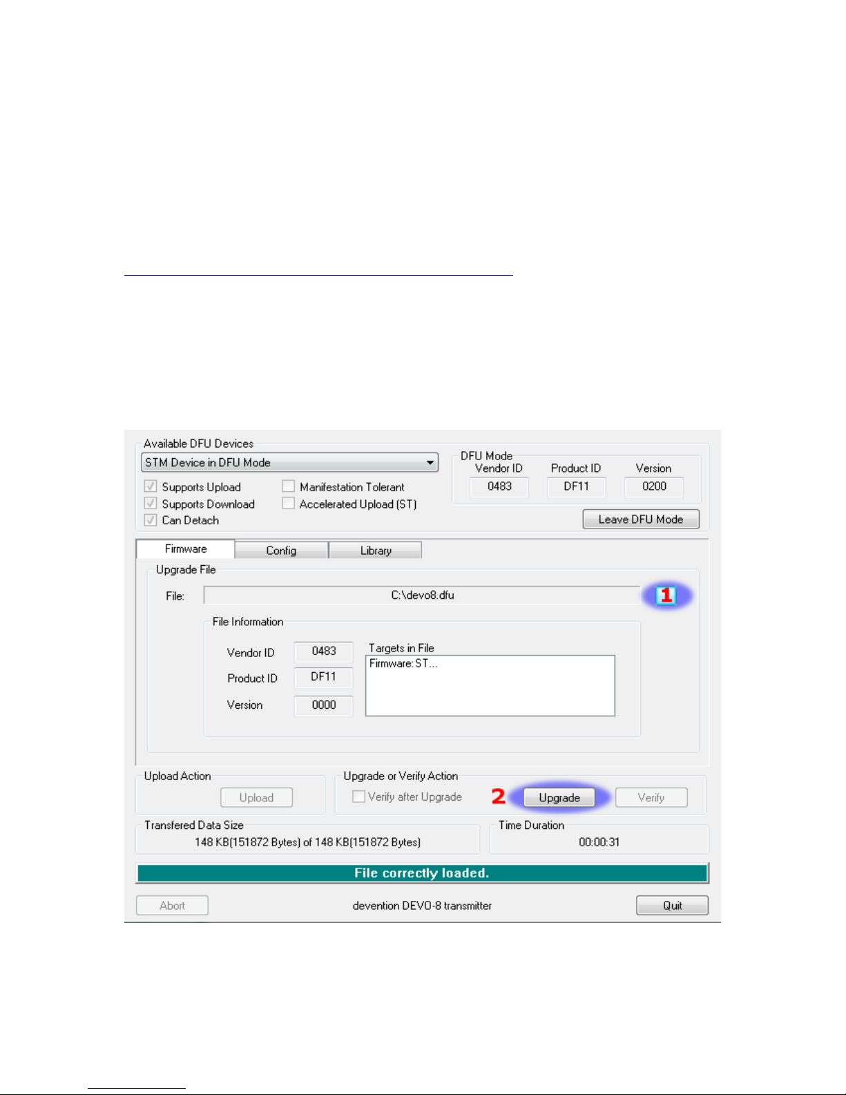
First install the deviation-devoXX-x.y.z.dfu firmware using the Walkera ‘DfuSe USB
Upgrade’ tool. You will need the ‘Devention DfuSe USB Upgrade Tool' from Walkera:
http://www.walkera.com/en/upload/upgrade/2013-2-26.rar. Do NOT attempt to use the
DfuSe tool from STMicroelectronics! It is recommended to test that this tool works by
upgrading to a different Walkera firmware. Several users have had compatibility issues
with the DfuSe tool.
Plug the transmitter into the PC via USB, and turn on the transmitter while holding
‘EXT’ to enter programming mode. On the Devo12, this is done by holding the trainer-
switch instead.
1) Press the ‘...’ button and select the dfu file to install
2) Select ‘Upgrade’ to install the firmware. This will be grayed-out if your Tx is not
detected. Do NOT use ‘Upload’ as this will destroy the dfu file on your PC
Page | 5

There have been reports of it corrupting the model settings on the TX as
well
3) Devo12 Only: Select the ’Library’ tab, click ‘..’ select the devo12-lib.dfu from the
file-system zip. Then ‘Upgrade’ the Library.
Turn off the transmitter, and turn back on while holding ‘ENT’. There should be a USB
logo on the screen.
If this is a first-time install of Deviation, the PC should prompt to format the drive.
Format using default options. Next unzip the deviation-fs-devoXX-x.y.z.zip to the Tx
USB drive.
If this is an upgrade from a previous Deviation release, it is strongly recommended to
back-up the ‘models’ directory from the transmitter as well as the tx.ini file to ensure you
don’t lose any model or transmitter configuration. Next unzip the deviation-fs-devoXX-
x.y.z.zip to the PC and copy all directories EXCEPT for the ‘models’ directory and the
tx.ini file to the transmitter. Optionally, copy the ‘models’ directory to the transmitter
except for the currently configured model files. This last step will ensure that the defaults
for newly created models have the latest options set. If the tx.ini file is overwritten, the
stick calibration must be repeated and any settings reset.
Page | 6

USB & File-system
Deviation stores all configuration, bitmaps, and models as regular files on the USB file-
system.
USB can be most easily enabled by holding down the ‘ENT’ button while powering up
the transmitter. Files can then be easily copied to or from the Tx.
The directory structure is as follows:
\tx.ini Transmitter config. Includes trim settings, calibration data,
and the last-used model number
\errors.txt If the firmware crashes or reboots, debug information will be
stored in this
\media\config.ini The color scheme and fonts for the transmitter
\media\sound.ini Contains notes to play for various alarms
\media\*.bmp Images used for the current Tx theme
\media\*.fon Font files
\models\default.ini The default model, loaded whenever a model is cleared
\models\model*.ini Configuration files for each model. Due to a limitation in the
firmware, Deviation cannot create new files. It is therefore
necessary to have a modelxx.ini for each model regardless of
whether it is currently in use.
\modelico\*.bmp All available model icons (must be 6x 6 pixels)
\templates\*.ini Configuration files used when loading predefined templates.
These are nearly identical to the model configuration files,
however they do not necessarily define all parameters
\language\lang*.* Language translation files. These are UTF-8 text files con-
taining the English string and the respective translated string
Reporting Bugs
To report bugs with the Deviation firmware, file a ticket at:
https://bitbucket.org/PhracturedBlue/deviation/issues
It is recommended that you create an account in order to be informed of updates to the
ticket, but this is not required.
Please include the Deviation version in all reports (find this on the USB/Version page)
If the bug includes a crash or reboot of the firmware, additionally include:
•The ‘.elf’ files that came with the firmware zip file.
•The errors.txt file from the transmitter
Page | 7
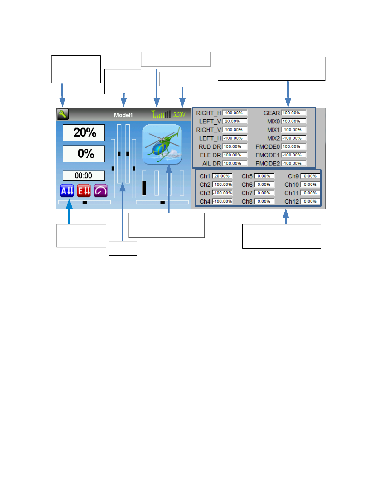
Main Page
Tx Options: Selecting this icon provides access to the main-page configuration screen;
the Channel-Test screen; telemetry output; the frequency scanner; and USB mode
Current Model: Selecting the model-name provides access to the Load-Model screen for
quick-model switching
Transmitter Power: This indicates the currently selected transmitter power. It is
configured from the Model Configuration page
Battery Voltage: Numerical representation of current Tx battery state
Configurable Displays: These can be text-boxes contacting input, channel, telemetry, or
timer data; bar graphs displaying channel data; or icons displaying specific states (e.g.
gear, flaps,…)
Trims: The trim display can be configured to show 0, 4 or 6 trims
Model Configuration: Selecting the model icon provides access to the model
configuration pages
Page | 8
Channel Output values
(Emulator Only)
Battery voltage
Current
Model
Click to edit
Tx Options
Configurable
displays
Trims
Click to enter
Model Configuration
Transmitter Power Raw input (stick/switch values)
(Emulator Only)

Navigating
The transmitter menus can be navigated via touch-screen or with the physical buttons.
With the touch screen, simply touching any button on the screen will immediately
activate it.
The gray spin-boxes act both as spin-boxes (for selecting a value) and as buttons (which
can have various effects). White spin-boxes do not act as buttons, and are only for value
selection.
When using the physical buttons, it is necessary to 1st enter navigation mode before the
buttons can be accessed.
On the main page, a long-press of the ‘ENT’ key will enter navigation mode.
On all other pages, pressing ‘UP’ or ‘DN’ will enter navigation mode
Once in navigation mode, the current widget will be highlighted, and UP/DN will select
the next/previous widget.
The ‘R+’ and ‘L-’ buttons are used on spin-box widgets to increase or decrease the
selected value. In some cases holding down the button will use larger step values to
move more quickly to the desired value.
For Buttons and gray spin-boxes, pressing ENT’ will press the button
Pressing ‘EXT’ will exit navigation mode. If pressed when not in navigation mode, it
will move back to the main screen
Menu Layout
Page |
Main Page Load Model
Current Model
Main Page
Telemetry
Timer
Model Configuration Pages
Main Page
Channels Inputs
Buttons
Tx Option Pages
USB/
Version Scanner
Main Page Config
ModelMixer
Tx Config
Trim
Telemetry

Emulator
The emulator provides a side-screen displaying the current virtual-stick/switch states as
well as the Channel output that would be received by the servos
The emulator controls are as follows (based an an English keyboard):
Button Action
q/a Left-Vertical stick (Throttle in mode 2)
Q/A Left-Vertical trim
w/s Left-Horizontal stick (Rudder in mode 2)
W/S Left-Horizontal trim
e/d Right-Vertical stick (Elevator in mode 2)
E/D Right-Vertical trim
r/f Right-Horizontal stick (Aileron in mode 2)
R/F Right-Horizontal trim
z Gear
x Rudder Dual-Rate switch
c Elevator Dual-Rate switch
v Aileron Dual-Rate switch
b Mix 0/1/2 switch
n FMode 0/1/2 switch
\ Power off
Left-arrow Left
Right-arrow Right
Up-arrow Up
Down-arrow Down
Enter Ent
Escape Exit
Version Page
The Deviation release version can be accessed by selecting the Configuration icon from
the main page, and moving left one page. It is also possible to enable USB from this
page. Note that doing so should never be done while the model is bound, as USB will
disrupt signal transmission!
Page | 10
Other manuals for Devo 6
1
This manual suits for next models
2
Table of contents
Other Deviation Transmitter manuals

Popular Transmitter manuals by other brands


Dejero
Dejero EnGo 3x manual

Rosemount
Rosemount 4600 Reference manual

Speaka Professional
Speaka Professional 2342740 operating instructions

trubomat
trubomat GAB 1000 instruction manual

Teledyne Analytical Instruments
Teledyne Analytical Instruments LXT-380 instructions

Rondish
Rondish UT-11 quick start guide


