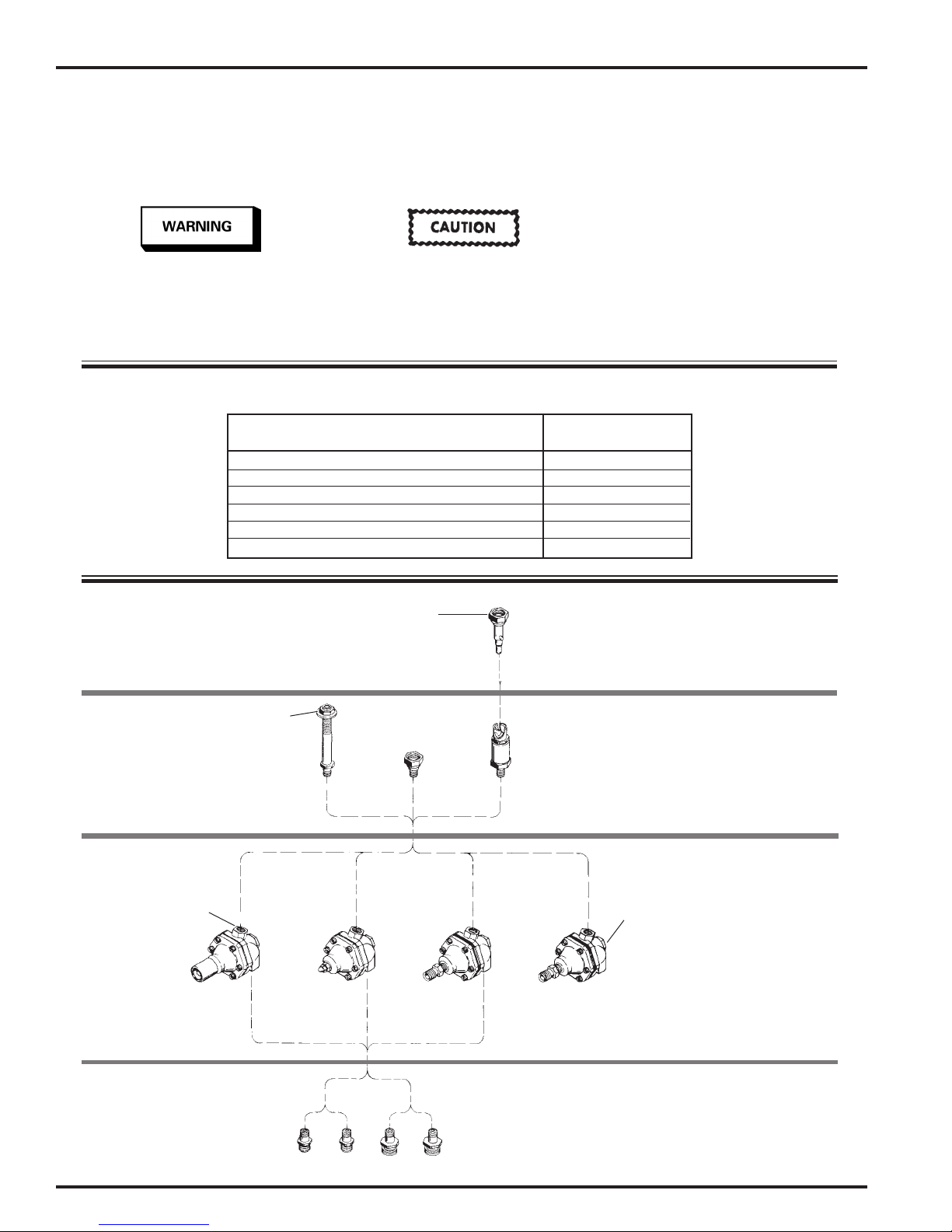
DeVilbiss HGS Series User manual

IMPORTANT: Read and follow all
instructions and safety precau-
tions before using this equip-
ment. Retain for future reference.
Manual
Regulator
Tamper Resistant
Regulator
Air Pilot
Regulator
GENERAL
This service bulletin covers installation,
operation, preventive maintenance, parts
replacement, and accessory items for HGS
Fluid Regulators.
MODEL IDENTIFICATION
HGS-5 X X X
DESCRIPTION
HGS Fluid Regulators provide regulation
of fluid to the spray gun without stopping
the flow of material which can cause set-
tling of pigmented materials.
NOTE
These regulators may be used
with materials containing chlo-
rinated solvents.
MODEL CHART
* Manual, non-circulating, single gun fluid regulator, primarily used in conjunction
with fluid pumps or dead end systems.
** Manual, non-circulating, can be attached to gun inlet or in line. Note: If used in
color change applications or with catalyzed materials, plug (24) must be removed
and the threads cleaned periodically.
Product
Identification
Control Type
1)Air Pilot
2)Manual Adjustment
3)Tamper Resistant
Adjustment
Fluid Inlet
Configuration
1) 1/4" NPSM(M) Fitting
2) 3/8" NPSM(M) Fitting
3) Non-Circulating 1/8" NPT(F)
Fluid Outlet
Configuration
1)Bayonet Lock
2)3/8" NPSM(F)
Swivel
3)1/4" NPSM(M)
Standpipe
9)3/8" NPSM(M)
CA PROP
65
PROP 65 WARNING
WARNING: This product contains chemicals
known to the State of California to cause
cancer and birth defects or other
reproductive harm.
HGS STAINLESS STEEL FLUID REGULATORS
SB-6-403-R1 (3/2018) 1 / 8 www.carlisleft.com
EN
SERVICE MANUAL

Important safety information --
a hazard that may cause serious
injury or loss of life.
Important information that tells
how to prevent damage to
equipment, or how to avoid a
situation that may cause minor
injury.
NOTE
Information that you should pay
special attention to.
SAFETY PRECAUTIONS
This manual contains information that is important for you to know and understand. This information relates to
USER SAFETY and PREVENTING EQUIPMENT PROBLEMS. To help you recognize this information, we use the fol-
lowing symbols. Please pay particular attention to these sections.
ACCESSORY
ITEMS
(STAINLESS STEEL)
OUTLET
CONNECTORS
(STAINLESS STEEL)
FLUID
REGULATOR
BASIC
ASSEMBLY
(WETTED PARTS
--STAINLESS STEEL
AND PTFE)
DUAL INLET ADAPTERS
CIRCULATING MODELS
ONLY
(STAINLESS STEEL)
NON-
RESTRICTED
FLOW
(HC-4691)
3/8" NPSM(F)
1/4" NPSM(M)
STANDPIPE
ASSEMBLY
(HGS-400)
3/8"
SWIVEL
(HC-1000, HGS-1) BAYONET
ASSEMBLY
(HGS-401-1)
TAMPER
RESISTANT
ADJUSTMENT
AIR PILOT
NON-CIRCULATING
3/8"
NPSM(M)
INLET
(HGS-21)
1/4"
NPSM(M)
INLET
(HGS-22)
AIR PILOT
CIRCULATING
MANUAL
ADJUSTMENT
1/8" NPT(F)
INLET
15° ANGLE
(ALL MODELS)
MODEL NUMBER TO REGULATOR BODY CROSS REFERENCE CHART
Body Number
Model Number (Less Fittings)
HGS-5112, HGS-5113, HGS-5122 HGS-452
HGS-5132, HGS-5133 HGS-453
HGS-5211, HGS-5212, HGS-5221, HGS-5222 HGS-451
HGS-5231, HGS-5232, HGS-5233, HGS-5239 HGS-455
HGS-5312, HGS-5313, HGS-5321 HGS-450
HGS-5242 HGS-461
EN
SB-6-403-R1 (3/2018)2 / 8www.carlisleft.com

TECHNICAL DATA
PSI (bar)
Fluid Inlet Pressure Min. 50 (3.5)
Max. 300 (20.7)
Regulated Fluid Min. 2 (0.14)
Pressure Range Max. 100 (6.9)
*Typical Flow Rates 150 to 2500 cc's/minute
oz's (grams)
Average Unit Weight
Models - Swivel 7.3 (210)
- Tamper Resist 7.9 (225)
- Standpipe 9.3 (265)
- Bayonet 9.7 (275)
Fluid oz's (ml)
Static Content
Models - Circulating 0.25 (7)
- Non-circulating 0.20 (5)
Wetted Parts 303 and 416 Stainless Steel,
PTFE
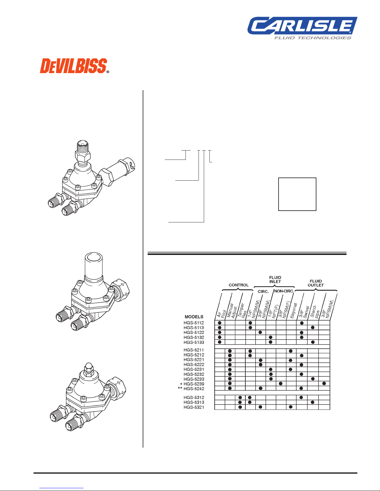
Models 17 models offered as standard
*Dependent upon viscocity and specific
gravity of material. Above information
based upon testing with mineral oil with
viscosity of 24 seconds #4 Ford, and
specific gravity of 0.84.
®Registered trademark of Dupont.
INSTALLATION
Risk of hazardous bursting or
equipment damage. Do not ex-
ceed 300 PSI (21 bar) maximum
fluid inlet pressure to regulator.
These regulators may be used
with most common coating and
finishing materials. However,
they are not designed for use
with highly abrasive materials.
If used with abrasive materials,
frequent and thorough cleaning
will be required, and replace-
ment of parts will be increased.
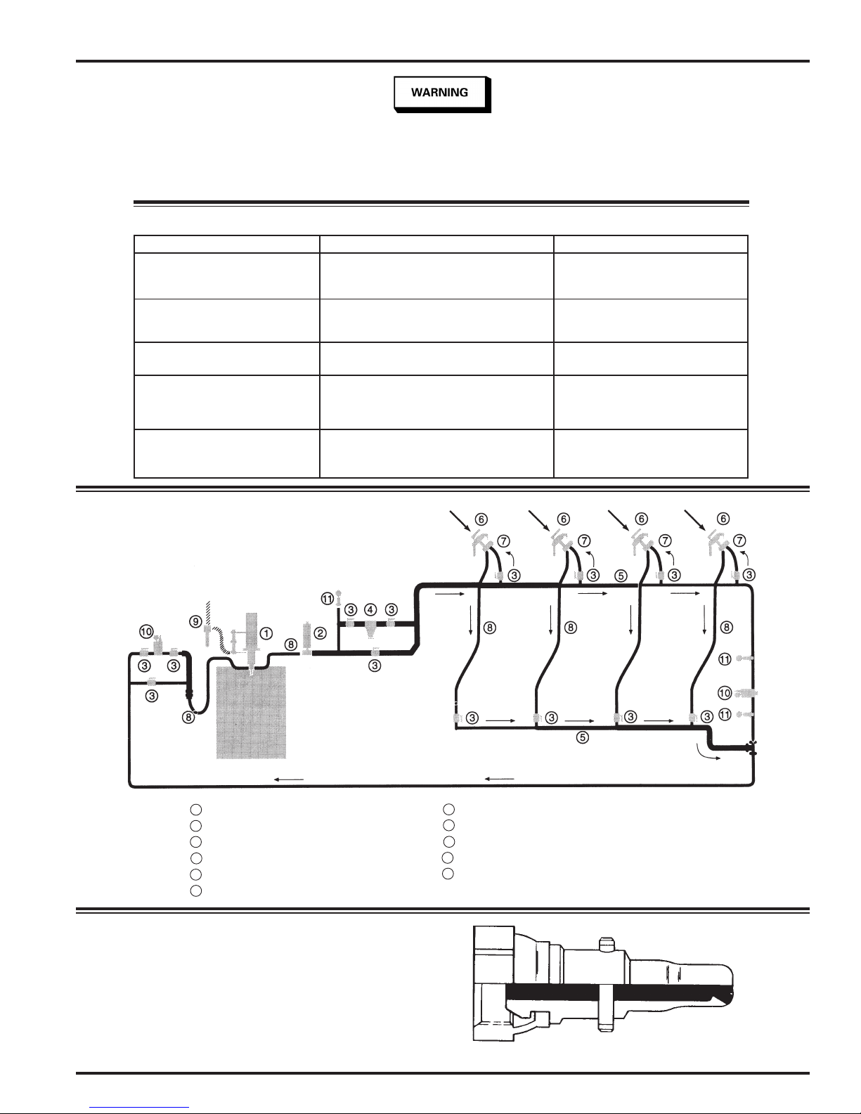
1. Where possible, mount the HGS
regulator as shown below with the
fluid outlet facing up. This will pre-
vent trapped air from causing erratic
operation. Trapped air can result
from an "air push" during a color
change cycle, or entrapped air in the
paint.
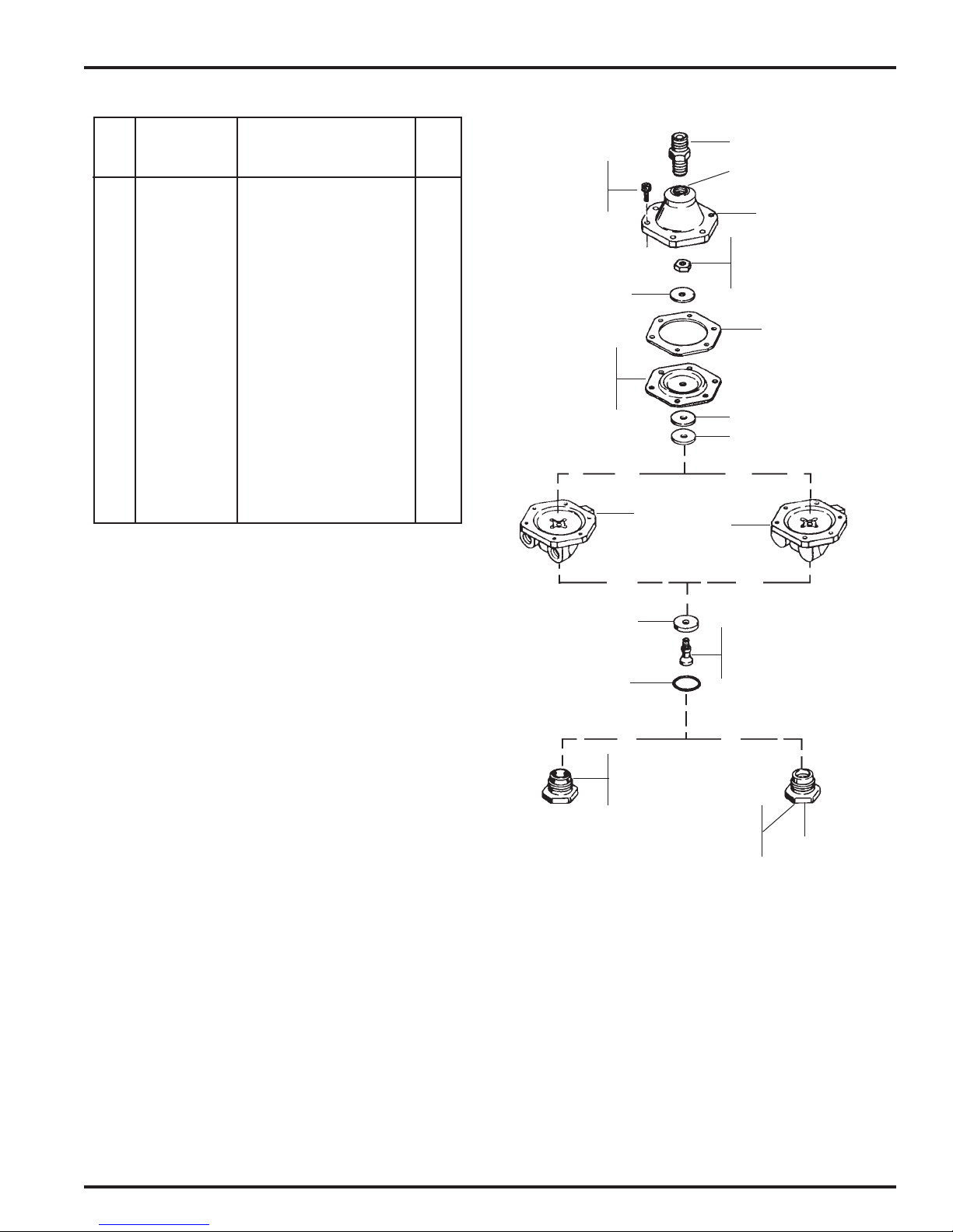
2. Connect fluid inlet supply hose.
Circulating Models
Connect the fluid supply hose to
either fluid inlet adapter (53 or 54).
Connect the return line to the other
adapter (53 or 54).
Non-Circulating Models
Connect the fluid supply hose to
inlet of plug (23 or 40).
3. Connect fluid outlet.
Bayonet Regulators
Attach the bayonet lock body (41) to
the bayonet quick disconnect stem
at the spray gun fluid inlet.
3/8" Swivel Regulators
Thread swivel nut (49) onto fluid inlet
of spray gun body.
Standpipe Regulators
Attach fluid supply hose from spray
gun to bulkhead fitting (52).
4. Connect air inlet.
Air Pilot Regulators
Attach regulated air supply to con-
nector (25).
OPERATION
Risk of hazardous bursting or
equipment damage. Do not ex-
ceed 300 PSI (21 bar) maximum
fluid inlet pressure to regulator.
Fluid pressure adjustment range is from
2 psi to 100 psi (0.1 bar to 6.9 bar).
Fluid pressure to regulator inlet is
300 psi (20.7 bar) maximum and 50 psi
(3.5 bar) minimum.
To Regulate Fluid Pressure on Manual
Adjust Models
1. Remove cap nut (1) and loosen lock
nut (2).
2. With a 3/32 inch hex key allen
wrench, adjust hex key allen set
screw (3) for desired pressure set-
ting. Turn set screw (3) clockwise to
increase and counterclockwise to
decrease pressure.
3. Retighten lock nut (2) after desired
pressure setting has been estab-
lished. Replace and tighten cap nut
(1).
To Regulate Fluid Pressure on Tamper
Resistant Models
1. Using T-handle (4B), loosen lock (6).
2. Engage adjusting screw (5) with torx
key (4A) and turn adjusting screw until
desired pressure setting is reached.
Turn torx key clockwise to increase
pressure and counterclockwise to
decrease pressure.
3. Using the torx key, hold adjusting
screw (5) from turning and tighten
lock (6) with the T-handle (4B).
To Regulate Fluid Pressure on Air Pilot
Models
Fluid pressure is controlled by means
of air pressure. To actuate fluid flow, a
minimum of 12-14 psi air pressure must
be applied to the bonnet.Attach one end
of regulated air line to connector (25)
and the other end of the air line to a
remote regulator. Increase air pressure
to increase fluid pressure, and decrease
air pressure to decrease fluid pressure.
Fluid pressure remains constant unless
air pilot regulator setting is altered.
PREVENTIVE MAINTENANCE
Cleaning
Total submersion of the fluid
regulator in solvent for cleaning
purposes will shorten the life
expectancy of the diaphragm.
The frequency with which the fluid
regulator should be cleaned will be the
same as the rest of the system in which
it is being used.
Bayonet Models
When spray gun is removed from service
and fluid regulator is not going to be used
for a period of time, the bayonet end
should immediately be soaked in solvent.
Do not submerge the entire regulator.
This will avoid hardening of material
around the ball and seat which may cause
leakage when regulator is put back in
service. The soaking container should be
an approved closed container if hazardous
solvents are used.
Fluid outlet should
face upward.
EN
SB-6-403-R1 (3/2018) 3 / 8 www.carlisleft.com

#4
5
6
7
TAMPER RESISTANT
MANUAL
ADJUSTMENT
1
2
3
8
TORQUE TO
15 LB.-IN.
(1.6 N•m)
12
TORQUE TO
6 LB.-IN.
(0.7 N•m)
10
13
14
11
9
15
PTFE (SMOOTH
GRAY SURFACE)
MUST FACE WETTED
SECTION 16
17
19 18
20
22
21
APPLY QH-130
THREAD
SEALANT
TO THREADS
24
TORQUE
TO 120 LB.-IN.
(13.5 N•m)
1/8"-27
NPT(F) Inlet
NON-CIRCULATING
PLUG
CIRCULATING
PLUG
MANUAL FLUID REGULATOR BODY ASSEMBLIES HGS-450,
HGS-451, HGS-455, HGS-461
Ind.
Ref. Replacement Parts
No. Part No. Description Req.
1 --- Cap Nut #10-32 1
2 --- Nut #10-32 1
3 --- Hex Key Allen Set 1
Screw, #10-32 x 3/4"
#4 KK-5047 T-Handle Kit
(Order Separately)
4A --- Torx Key 1
4B --- T-Handle 1
5 --- Torx Screw 10-32 Thd. 1
6 HGS-36 Lock 1
7 HGS-34 Guard 1
8 SSF-3169-K6 Socket Head Cap Screw, S.S. 6
#8-32 x 3/8" (Kit of 6)
9 HGS-5 Bonnet 1
10 HGS-28 Adjustment Seat 1
11 HGS-30 Regulator Spring 1
*12 --- Hex Nut #6-32 1
*13 --- Upper Plate 1
*14 HGS-12-K5 Gasket (Kit of 5) 1
*15 HGS-20-1 Diaphragm, PTFE 1
*16 SSN-57 Washer, PTFE 1
17 SSN-54 Flat Washer 1
18 HGS-8 Regulator Body, 1
Non-Circulating
HGS-59 Regulator Body, 1
Non-circulating, 1
for Model HGS-5242
19 HGS-7 Regulator Body, Circulating 1
*20 HGS-43-K5 Valve Seat, PTFE, 1
Std. Flow (Kit of 5)
21 HGS-44 Valve Stem, Std Flow 1
*22 SSG-8144 O-ring, PTFE 1
23 HGS-27 Plug, Non-Circulating 1
+24 HGS-26 Plug, Circulating 1
* QH-130 Loctite 1
Dual Inlet Fittings supplied with regulator (see page 8).
Manual Adjustment Fluid Regulator includes items 1 through
3 and 8 through 24.
Tamper Resistant Fluid Regulator includes items 5 through 24.
# To maintain the “tamper-proof" security feature, the
KK-5047 T-Handle is not included with each regulator, as
one T-Handle will service multiple regulators.
NOTE: KK-5047 T-Handle must be purchased separately.
Suffix -K5 designates kits of multiple parts.
* Parts included in Regulator Repair Kit KK-4456 (Std Flow).
+ HGS-5242 Model uses the circulating plug.
23
TORQUE TO
120 LB.-IN.
(13.5 N•m)
4A
4B
EN
SB-6-403-R1 (3/2018)4 / 8www.carlisleft.com

AIR PILOT FLUID REGULATOR BODY ASSEMLBLIES HGS-452
AND HGS-453
Ind.
Ref. Replacement Parts
No. Part No. Description Req.
25 H-1766 Connector 1/8" NPT(M) 1
x 1/4" NPSM(M)
26 SSF-3169-K6 Socket Head Cap Screw,
S.S. #8-32 x 3/8" (Kit of 6) 6
27 HGS-4 Bonnet 1
*28 HGS-12-K5 Gasket (Kit of 5) 1
*29 Hex Nut #6-32 1
*30 Upper Plate 1
*31 HGS-20-1 Diaphragm, PTFE 1
*32 SSN-57 Washer, PTFE 1
33 SSN-54 Flat Washer 1
34 HGS-7 Regulator Body, 1
Circulating
35 HGS-8 Regulator Body, 1
Non-Circulating
*36 HGS-43-K5 Valve Seat, PTFE 1
(Kit of 5)
37 HGS-44 Valve Stem 1
*38 SSG-8144 O-ring, PTFE 1
39 HGS-26 Plug, Circulating 1
40 HGS-27 Plug, Non-Circulating 1
* QH-130 Loctite 1
Dual Inlet Fittings supplied with regulator (see page 8).
Air Pilot Fluid Regulator, Circulating, includes items 25 through
34 and 36 through 39.
Air Pilot Fluid Regulator, Non-Circulating, includes items 25
through 33, 35 through 38 and 40.
Suffix -K5 designates kits of multiple parts.
*Parts included in Regulator Repair Kit KK-4456.
26
TORQUE TO
15 LB.-IN.
(1.6 N•m) 27
1/8"-27 NPT(F)
25
29
TORQUE TO
6 LB.-IN.
(0.7 N•m)
33
32
28
31
PTFE (SMOOTH
GRAY SURFACE)
MUST FACE WET-
TED SECTION
34 35
30
37
APPLY QH-130
THREAD SEALANT
TO THREADS
36
38
40
TORQUE TO
120 LB.-IN.
(13.5 N•m)
39
TORQUE TO
120 LB.-IN.
(13.5 N•m)
NON-CIRCULATING
PLUG
1/8" - 27
NPT(F)
INLET
CIRCULATING
PLUG
EN
SB-6-403-R1 (3/2018) 5 / 8 www.carlisleft.com

FLUID OUTLET CONNECTORS
Ref. Replacement Ind.
No. Part No. Description Parts Req.
41 HC-370-1 Bayonet Lock Body 1
42 --- Not Used
*43 --- Stem Seal 1
*44 --- Ball Seat 1
*45 --- Stainless Steel Ball 1
7/16" Diameter
*46 --- Spring 1
47 HGS-25 Bayonet Body 1
*KK-5061 Repair Kit
Ref. Replacement Ind.
No. Part No. Description Parts Req.
48 HGS-1 Tail Piece 1
49 HC-1000-K5 Swivel Nut 3/8" NPS(F) 1
(Kit of 5)
Ref. Replacement Ind.
No. Part No. Description Parts Req.
50 MBD-11-K5 Lock Nut (Kit of 5) 1
51 --- Lock Washer, Shake- 1
Proof, 9/16)
52 --- Bulkhead Fitting 1
FLUID INLET ADAPTERS
Ref. Replacement Ind.
No. Part No. Description Parts Req.
53 HGS-22 1/4" Stainless Steel 2
Inlet Adapter
54 HGS-21 3/8" Stainless Steel 2
Inlet Adapter
48
49
50
51
52
1/8-27 NPT(M)
53
1/8-27 NPT(M)
1/4-18 NPSM(M)
1/4-18 NPSM(M)
54
1/8-27 NPT(M)
3/8-18 NPSM(M)
HGS-400
Stand Pipe
Swivel Adapter
1/8-27 NPT(M)
NOTE
Use a PTFE based thread sealant on the
threads of inlet adapters (53 and 54), and
threads of fittings on outlet connectors (47,
48 and 52).
HGS-401-1
Bayonet
Assembly
1/8-27 NPT(M)
41
43
44
45
46
47
EN
SB-6-403-R1 (3/2018)6 / 8www.carlisleft.com

Pressurized parts cause a risk of injury if disassembled. Shut off and
relieve pressure before disconnecting hoses from the fluid regulator.
Cleaning or servicing is required if the regulator does not: regulate fluid, maintain its pressure setting, or leaks fluid. To service
regulator, relieve pressures, disconnect regulator from spray gun and hoses from regulator. Disassemble regulator; refer to exploded
views. Clean and inspect parts carefully. Replace worn or damaged parts and reassemble regulator.
TROUBLESHOOTING CHART
PROBLEM CAUSE REMEDY
No flow or insufficient pressure Plugged fluid path Disassemble and clean fluid
regulation passages.
Defective diaphragm Replace diaphragm (Ref. 15 or 31).
Excessive fluid flow Worn seat Replace seat (Ref. 20 or 36).
Worn stem Replace stem (Ref. 21 or 37).
Material viscosity low Check material viscosity.
Material leaking under bonnet Bonnet screws (SSF-3169) have Check screw torque.
come loose specifications.
Pressure creep Foreign material or dirt Clean seat and stem.
on seat or stem
Worn seat Replace seat (Ref. 20 or 36).
Worn stem Replace stem (Ref. 21 or 37).
Erratic fluid pressure Air trapped in regulator body Mount regulator in a vertical
position; input port at bottom,
output port at top.
Circulating Loop With Graduated Return Lines
1 Pump Assembly/Low Ratio 7 Gun Mounted, HGS Fluid Regulator
2 Pulsation Chamber 8 Fluid Hose Assembly
3 Fluid Shut-Off Valve 9 Oil and Moisture Separator/Extractor Dryer
4 Filter/Fluid Outlet 10 Back Pressure Regulator/Low Pressure
5 Graduated Supply and Returns Lines 11 Pulsation Proof Gauge
6 Air Atomized Spray Gun/Manual or Automatic
ACCESSORY ITEMS
HC-4691 — 3/8" NPSM(F) STEM, STAINLESS STEEL
Unrestricted fluid passage, for use with standard spray gun.
SERVICE
TYPICAL MANUAL SPRAY GUN SYSTEM
EN
SB-6-403-R1 (3/2018) 7 / 8 www.carlisleft.com

EN
SB-6-403-R1 (3/2018)8 / 8www.carlisleft.com
WARRANTY POLICY
This product is covered by Carlisle Fluid Technologies’ materials and workmanship limited warranty.
The use of any parts or accessories, from a source other than Carlisle Fluid Technologies,
will void all warranties. Failure to reasonably follow any maintenance guidance provided
may invalidate any warranty.
For specic warranty information please contact Carlisle Fluid Technologies.
For technical assistance or to locate an authorized distributor,
contact one of our international sales and customer support locations.
Region Industrial/Automotive Automotive Renishing
Americas Tel: 1-800-992-4657 Tel: 1-800-445-3988
Fax: 1-888-246-5732 Fax: 1-800-445-6643
Europe, Africa,
Middle East, India
Tel: +44 (0)1202 571 111
Fax: +44 (0)1202 573 488
China Tel: +8621-3373 0108
Fax: +8621-3373 0308
Japan Tel: +81 45 785 6421
Fax: +81 45 785 6517
Australia Tel: +61 (0) 2 8525 7555
Fax: +61 (0) 2 8525 7575
Carlisle Fluid Technologies is a global leader in innovative nishing technologies.
Carlisle Fluid Technologies reserves the right to modify equipment specications without prior notice.
DeVilbiss®, Ransburg®, ms®, BGK®, and Binks®
are registered trademarks of Carlisle Fluid Technologies, Inc.
©2018 Carlisle Fluid Technologies, Inc.
All rights reserved.
For the latest information about our products, visit www.carlisleft.com
This manual suits for next models
23
Table of contents
Other DeVilbiss Control Unit manuals
Popular Control Unit manuals by other brands

Saxby Lighting
Saxby Lighting Reed 10785 Instruction leaflet

Motion Control Engineering
Motion Control Engineering Nidec iControl user guide

Pilz
Pilz PSS u2 ES 4AO U/I operating manual

Magnetic
Magnetic MGCplus manual

Sony
Sony FCB-ER8550 Technical manual

ITOH DENKI
ITOH DENKI POWER MOLLER PLUS F-RAT-NX75 user manual

Elatec
Elatec TWN4 MultiTech 2 HF manual

Pickering
Pickering 40-574 user manual

GEA
GEA VARIVENT FRS Operating instruction

Cemline Corporation
Cemline Corporation CEM-TROL Installation, operation and maintenance manual

GatesAir
GatesAir PT-353 Installation and operation manual

Siemens
Siemens LEC1 Series manual