DeVilbiss QS-5001 Reference manual

SERVICE BULLETIN
SB-19-085-P
Replaces SB-19-085-N
IMPORTANT: Read and follow all instruc-
tions and SAFETY PRECAUTIONS before
using this equipment. Retain for future
reference.
QS-5001 AIR MOTOR DRIVE
DESCRIPTION
The QS-5001 air motor covered in this
service bulletin is designed to drive paint
agitators when connected to a source of
clean, dry, air pressure. Maximum air
input 100 PSI.
QS-5001 standard duty air motor drive,
1/4 h.p., 15:1 ratio, 20 to120 RPM for pres-
sure tank agitator. Includes air adjusting
valve with necessary hose and fittings for
hookup to tank regulator. Overall height
8", width 7-3/4".
High pressure can cause serious
injury. Pressure is maintained in
a pressure tank after the system
has been shut down. Before
attempting removal of fill plug
or cover, relieve tank pressure.
Pressure Relief Procedure
1. Turn off the main air supply to the
tank.
2. Close air inlet valve located on tank
air manifold.
3. Bleed off air in the tank by turning
the relief valve handle counter-
clockwise. Wait until all the air has
escaped through the valve before
removing the pressure tank cover
or fill plug.
4. Leave the air relief valve open until
you have reinstalled the cover or fill
plug.
INSTALLATION
QS-5001 Installation onto Pressure Tank
with Agitator. (Refer to Figure 1.)
1. Place support (12) over agitator bear-
ing housing in tank lid and tighten in
place. Tighten setscrew (14) in either
screw hole.
2. Set air motor drive on support (12)
so that gear box shaft (35) engages
agitator shaft. Tighten cap screw (13).
3. For single regulation proceed as fol-
lows:
a. Remove air inlet valve from regula-
tor on tank and install service tee (1)
in regulator.
b. Reinstall air inlet valve in service
tee (1).
c. Install nipple (2) in service tee (1).
Install hose assembly (3) between
nipple and air adjusting valve (4) on
air motor.
4. For double regulation proceed as fol-
lows:
a. Remove plug from main line
port of lower regulator and install
nipple(2).
b. Install hose assembly (3) between
nipple (2) and air adjusting valve (4)
on air motor.
OPERATION
Open valve to main air line; then slowly
open air adjusting valve until agitator
turns. To extend air motor life, adjust air
pressure setting to run motor at about one
revolution per second. The agitator should
be run continuously while using the tank.
PREVENTIVE MAINTENANCE
Air Motor Lubrication
Failure to properly lubricate
the air motor will result in
premature motor failure and
will void warranty.
Lubricate air motor daily by
adding 4 or 5 drops of SAE 10
weight oil into air inlet fitting.
Periodically - Remove air adjusting valve
and air strainer and flush motor with a
clean suitable solvent. Remove trapped
particles from screen in air inlet and clean
air strainer felt.
Air Motor Gear Box Lubrication
Every 2 Days - Remove oil fill plug and
check oil level. If oil level is low, add
140-weight SAE Gear Oil or a high quality
worm gear lubricant. Replace pipe plug
and tighten to 20 foot-pounds (27 N.m)
of torque.
Note
Gear box oil is most easily
drained just after motor opera-
tion, while oil is still warm.
Note
Do not overfill. Overfilling may
cause oil to leak out of vent cap
on top of gear box.
Approx. 1/8" Gap
(top of oil level to
bottom of fill hole)

PAGE 2 SB-19-085-P
SAFETY PRECAUTIONS
This manual contains important information that all users should know and understand before using the equipment. This informa-
tion relates to USER SAFETY and PREVENTING EQUIPMENT PROBLEMS.
To help you recognize this information, we use the following terms to draw your attention to certain equipment labels and portions
of this Service Bulletin.
Please pay special attention to any label or information that is highlighted by one of these terms:
HAZARD CAUSE SAFEGUARDS
Fire Solvents and coatings can be 1. Adequate exhaust must be provided to
highly flammable or combust- keep the air free of accumulations of
ible, especially when sprayed. flammable vapors.
2. Smoking must never be allowed in the
spray area.
3. Fire extinguishing equipment must be
present in the spray area.
Explosion Hazard - Making changes to pressure 1. Never drill into, weld or modify tank in
Pressure Tank Rupture tank will weaken it. any way. Carefully follow all instructions
for motor drive installation.
2. Do not adjust, remove, or tamper with
the safety valve. If replacement is nec-
essary, use the same type and rating of
valve.
Explosion Hazard - Halogenated hydrocarbon solvents - Aluminum is widely used in spray application
Incompatible Materials for example: methylene chloride and equipment - such as material pumps, cups,
1,1,1, - Trichloroethane are not regulators, valves, etc. Check all equipment
chemically compatible with the items before use and make sure they can be
aluminum that might be used in many used safely with these solvents. Read the
system components. The chemical label or data sheet for the material you in-
reaction caused by these solvents tend to spray. If in doubt as to whether or
reacting with aluminum can become not a coating or cleaning material is com-
violent and lead to an equipment patible, contact your material supplier. Any
explosion. other type of solvent may be used with alu-
minum equipment.
Note
Information that you should pay
special attention to.
Important information to alert you to a
situation that might cause serious injury
if instructions are not followed.
Important information that tells how to
prevent damage to equipment, or how
to avoid a situation that might cause
minor injury.
The following hazards may occur during the normal use of this equipment. Please read the following chart.
CA PROP
65
PROP 65 WARNING
WARNING: This product contains chemicals
known to the State of California to cause cancer
and birth defects or other reproductive harm.

SB-19-085-P PAGE 3
After first 250 hours of operation, remove
gear box and drain gear oil. Refill gear
box with 140-weight SAE Gear Oil or a
high quality worm gear lubricant. Replace
pipe plug and tighten to 20 foot-pounds
(27 N.m) of torque.
6 Months or 2500 Operating Hours -
Replace gear oil according to instructions
above. Replace gear oil more often if
environment causes oil to become con-
taminated during use.
REPLACEMENT OF PARTS
Removal of Air Motor and Gear Box
(Refer to Figure 1 - typical assembly.)
1. Follow pressure relief procedure
(Pg. 1) before removing or loosening
any components.
2. Turn off valve to main air supply and
disconnect air adjusting valve (4) at
nipple (2).
3. Loosen upper cap screw (13) and
remove air motor and gear box
assembly from support (12).
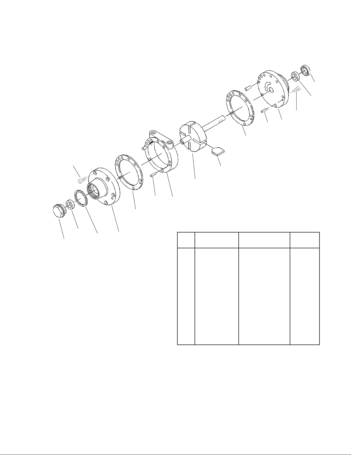
Air Motor (Refer to Figure 2.)
Holes must be drilled for new dowel pins
(21) after assembling front plate (26) on
new body (25) for alignment of parts.
Do not pry front plate (26) or end plate (20)
from air motor body (25) with a screw-
driver; this will dent the surface of the
body and plates, causing leaks. A puller
tool should be used to remove the plate
from the motor body while maintaining
the position of the shaft.
Always install two new gaskets (22)
when reassembling air motor.
Assemble the end plates to the body
using an arbor press with a pusher acting
on both races of the bearing while rigidly
supporting the opposite (drive) end of
the shaft.
Gear Box (Refer to Figure 3.)
1. Remove oil fill plug (37) or cover plate
(33) and drain gear box lubricant.
2. Remove set screws (40) and gear
box (16, Figure 1) from air motor (15,
Figure 1).
3. Disassemble gear box per exploded
view, Figure 3. Discard gaskets (36 and
41). Do not remove oil seal (39) unless
leakage or seal damage is indicated.
4. If oil seal (39) was removed, inspect
seal seating bore in housing (38).
Remove any burrs or contaminants
from seal seating bore. Burrs or con-
taminants could distort new oil seal
during installation.
5. Inspect gear and shaft assembly
(35) for wear grooves, burrs, or con-
tamination of seal seating area. If seal
seating area is damaged, shaft must
be repaired or replaced.
6. Inspect all other parts for wear spots,
chipping, or other damage. Replace
damaged or worn parts.
7. If oil seal (39) is being replaced,
inspect new seal for damage before
installing. Use arbor press to install
seal. Press fixture diameter must be
close fit with gear box bore diameter
to avoid damage to seal. Install with
inner casing and sealing lip toward
bottom of bore. Drive seal squarely
into bore to avoid warping. Check
that seal is fully seated all around at
bottom of bore.
8. Reassemble gear box per exploded
view. Install new gaskets (36 and 41).
Just prior to assembling gear box
with air motor, apply a small dab
of thread locking compound (30) to
threads of set screws (40). Connect
motor and gear box and torque set
screws (40) to 60 inch-pounds (6,8
N.m), minimum. Refill gear box per
gear box lubrication instructions.

PAGE 4 SB-19-085-P
FIGURE 1 GEAR DRIVE AIR MOTOR
QS-5001 (STANDARD DUTY)
Oil
Fill
16
See Figure 3
for Gear Box
Assembly
7
10
9
8
8
6
4
3
5
2
11 13
12
15
See
Figure 2
for Air
Motor.
14
1
Ref Replacement Ind. Parts
No. Part No. Description Req'd.
1 --- Service Tee 1/4" 1
Galvanized
Purchase Locally
2 H-2008
Nipple 1/4" NPS(M)
2
x 1/4" NPT (M)
3 HA-5863 Hose Assembly 1-1/2 ft. 1
4 HAV-500
Air Adjusting Valve
1
1/4" NPS(M) x
1/4" NPS(F)
5 --- Street Elbow 1
1/4"(M) x 1/4"(F)NPT
Purchase Locally
6 350-401 Air Strainer Assembly 1
7 --- Strainer Cap 1
*8 --- Screen 2
*•9 --- Felt 1
10 --- Strainer Body 1
11 32243-133 Washer 1
12 QS-70-2 Support 1
13 Hex Head Cap
Screw 3/8"-16 x 2"
1
Purchase Locally
14 --- Square Head Set
Screw 1/4-20 x 3/8"
Purchase Locally
15 --- Air Motor (Figure 2) REF
16 --- Gear Box (Figure 3) REF
•Included in KK-5001-1 Air Motor Repair Kit (See Pg. 5
for
additional items provided in kit.)
*Ref. No. (8) 2 ea. and Ref. No. (9) 4 ea. included in KK-5006
Strainer Screen and Felt Kit.
2

SB-19-085-P PAGE 5
FIGURE 2
QS-4016 AIR MOTOR
Ref Replacement Ind. Parts
No. Part No. Description Req'd.
17 QS-336 Oil Seal 1
18 QS-197 Bearing 1
19 Purchase Locally Machine Screw 12
1/4-28 x 1/2
20 QS-334 End Plate 1
21 QS-189-1-K10 Dowel Pin 4
(Kit of 10)
•22 PT-59-K10 End Plate Gasket 2
Kit (Kit of 10)
•23 --- Vane 4
24 QS-442 Rotor and Shaft 1
25 QS-335 Body 1
26 QS-333 Front Plate 1
•27 --- End Cap Gasket 1
28 PT-58 Bearing 1
29 QS-190 End Cap 1
•Parts available in Air Motor Repair Kit. Order KK-5001-1.
19
29
28 27 26
22
21 25
23
22
21 20
19
18
17
24

PAGE 6 SB-19-085-P
Ref Replacement Ind. Parts
No. Part No. Description Req'd.
30 --- Thread Locking __
Compound - not
shown
*31 --- Fillister Head 4
Machine Screw
10-24 x 5/8"
32 QS-108 Pressure Relief 1
Fitting
33 QS-37-1 Cover Plate 1
*34 --- Washer 1
35 QS-416-1 Gear and Shaft Assy. 1
*36 --- Gasket 1
37 --- Pipe Plug 1/4", 1
Galvanized
Purchase Locally
38 QS-36-1 Housing 1
*39 --- Oil Seal 1
*40 --- Cup Point Set-Screw 2
5/16-18 x 3/8"
*41 --- Gasket 1
42 QS-59 Worm Gear 1
*43 --- Spacer 1
*44 --- Key, No. 5, 5/8" x 1/8" 1
FIGURE 3 GEAR BOX ASSEMBLY
When Replacing Ref. No. 31, Torque to 15
in-lbs. min. When Replacing Ref. No. 40,
Torque to 60 in-lbs. min. Apply SS-9868
Sealant to Threads as Needed.
40
41
42
43
40
Air
Motor Shaft
38
39
37
36
35
34
33
32
31
44
*Parts included in KK-5010 Gear Box Kit.

SB-19-085-P PAGE 7
CONDITION CAUSE CORRECTION
AIR MOTOR DRIVE SERVICE CHECKS
A. Air motor sluggish or inefficient. 1. Air motor needs cleaning.
2. Motor vanes need replacing or
contaminants present in motor
chamber, Figure 2.
3. Low oil level in gear box, Figure 3.
4. Gear and shaft assembly (36) and/or
worm gear (43) worn, Figure 3.
5. Air motor bearing (19 or 29) worn,
Figure 2.
1. Disassemble and clean per parts
replacement instruc-tions.
2. Disassemble, clean motor per parts
replacement instructions. Replace
worn vanes.
3. Add oil per lubrication instructions.
4. Replace worn parts per parts
replacement instructions.
5. Replace bearings per parts
replacement instructions.
B. Oil leakage from gear box. 1. Seal (40, Figure 3) worn. 1. Replace seal per parts replacement
instructions.

PAGE 8 SB-19-085-P
SERVICE BULLETIN REVISIONS
Refer to the following chart for Part No./Literature changes
Part No. Changes
Old Part No. New Part No. Interchangeability Literature Changes
KK-5001-2 Air Motor KK-5001-1 Air Mtr. Repair Kit Directly. 1. Revised Figure 2.
Repair Kit
PT-77-K10 End Plate PT-59-K10 End Plate Gasket Kit Directly.
O-Ring
7/11 ©2011 DeVilbiss All rights reserved. Printed in U.S.A.
U.S.A. / Canada Customer Service
195 Internationale Blvd.
Glendale Heights, IL 60139
630-237-5000
Toll Free Customer Service
and Technical Support
800-992-4657
Toll Free Fax
888-246-5732
DeVilbiss Sales and Service: www.devilbiss.com
WARRANTY
This product is covered by DeVilbiss’ 1 Year Limited Warranty.
Table of contents
Other DeVilbiss DC Drive manuals
Popular DC Drive manuals by other brands

YASKAWA
YASKAWA E7 Drive installation guide

EUCHIPS
EUCHIPS EUP75D-1H12V-0 quick start guide

Iomega
Iomega REV Loader 280 quick start guide

Hettich
Hettich LegaDrive Touch Comfort FX installation instructions

Toshiba
Toshiba XM-6201B installation manual

SCHUNK
SCHUNK IndraDrive CS Series Commissioning instructions