DeWalt DWE575 User manual

ww
w. .
com
DWE575
DWE576

2
English (original instructions) 11
23
Copyright DeWALT

1
Figure 1
jj
h
d
a
e
bc
g
k
ji
f
m
l
DWE576
aa z
DWE575
h

2
d
p
c
q
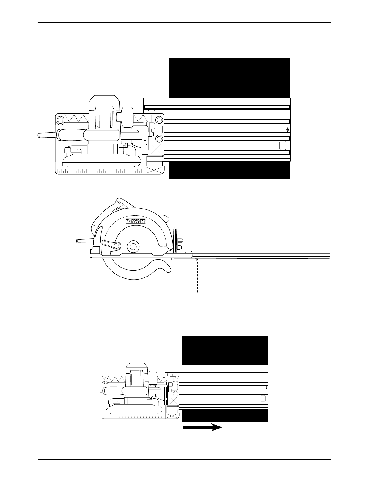
Figure 4
Figure 6
s
r
q
t
Figure 3
Figure 5
l
j
n
ko
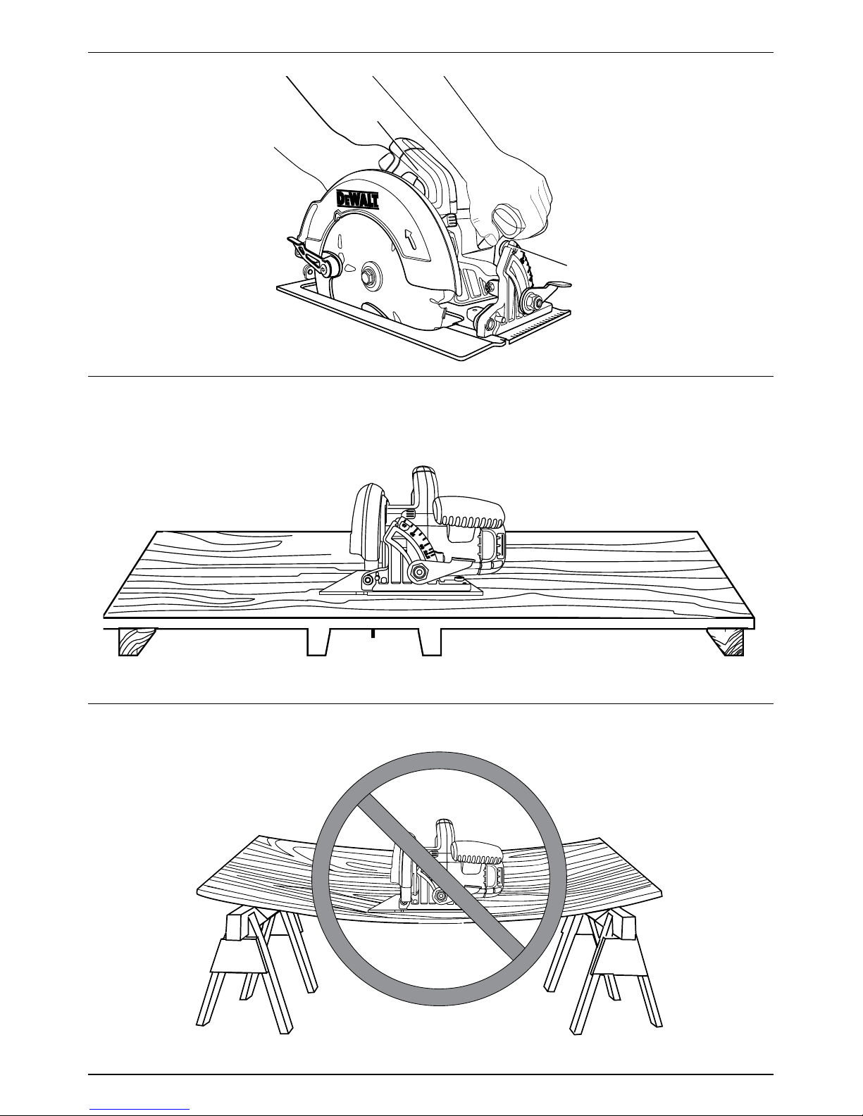
Figure 7
Figure 2

3
Figure 9
Figure 8
Figure 10
g
h
u
v
w
DWE575 DWE576

4
Figure 11
Figure 12
bb
dd
cc
Figure 13
gg
gg
gg
x
y
i
m

5
Figure 15
ff
bb
100
mm 20 mm
Figure 14
ee
ee
bb
DWE576
DWE576
6
Figure 17
Figure 16

7
Figure 18
Figure 20
ee ee
45˚ 0˚
45° 0°
Figure 19
Figure 21
DWE576
DWE575
45° 0°
8
Figure 24
Figure 23
b
f
Figure 22
Other manuals for DWE575
5
This manual suits for next models
1
Table of contents
Other DeWalt Saw manuals

DeWalt
DeWalt D36000 User manual

DeWalt
DeWalt D28730 Series User manual

DeWalt
DeWalt DWE550 User manual

DeWalt
DeWalt DW708 User manual

DeWalt
DeWalt DCS572 User manual

DeWalt
DeWalt DW328 User manual

DeWalt
DeWalt DW008 User manual

DeWalt
DeWalt DW710 TYPE 2 User manual

DeWalt
DeWalt DW744 User manual

DeWalt
DeWalt Dhs790at2 User manual

DeWalt
DeWalt 14'' Metal/wood cutting band saw User manual

DeWalt
DeWalt DCS570 User manual

DeWalt
DeWalt DW715 User manual

DeWalt
DeWalt D28700 User manual

DeWalt
DeWalt DWE357 User manual

DeWalt
DeWalt DCS369E1 User manual

DeWalt
DeWalt DC390 User manual

DeWalt
DeWalt DC495 Guide

DeWalt
DeWalt DW368 User manual

DeWalt
DeWalt DW712 User manual


