DEWESOFT NEMOSENSE Product manual

NEMOSENSE
TECHNICAL REFERENCE MANUAL
NEMOSENSE V23-1
1

NEMOSENSE
TECHNICAL REFERENCE MANUAL
Table of contents
Table of contents 2
1. Introduction 3
2. Operational principle 3
3. Getting started with NEMOSENSE 4
Dewesoft NEMOSENSE Config Tool App 4
Dewesoft Historian software 4
Configuration mode 5
Operational mode (measurement) 11
Synchronization 12
Meaning of LEDs 12
4. Specifications 14
General device specifications: NEMOSENSE 14
Measurement specifications: 3xMEMS-ACC 15
Dimensional drawing: NEMOSENSE-3xMEMS-ACC 16
About this document 16
Legend 17
Online versions 17
Device Technical Reference Manual 17
DEWESoft® User Manual (Not Yet Supported with NEMOSENSE) 17
Warranty information 17
Calibration 18
Support 18
Service/repair 18
Restricted Rights 18
Printing History 18
Copyright 19
Trademarks 19
Safety instructions 19
Safety symbols in the manual 19
General Safety Instructions 19
Environmental Considerations 19
Product End-of-Life Handling 20
System and Components Recycling 20
General safety and hazard warnings for all Dewesoft systems 20
Documentation version history 22
NEMOSENSE V23-1 2/23

NEMOSENSE
TECHNICAL REFERENCE MANUAL
1. Introduction
Dewesoft NEMOSENSE is a family of low power devices designed for remote monitoring. NEMOSENSE
devices acquire data, store it to an internal memory and send it to the server when connection is
available.
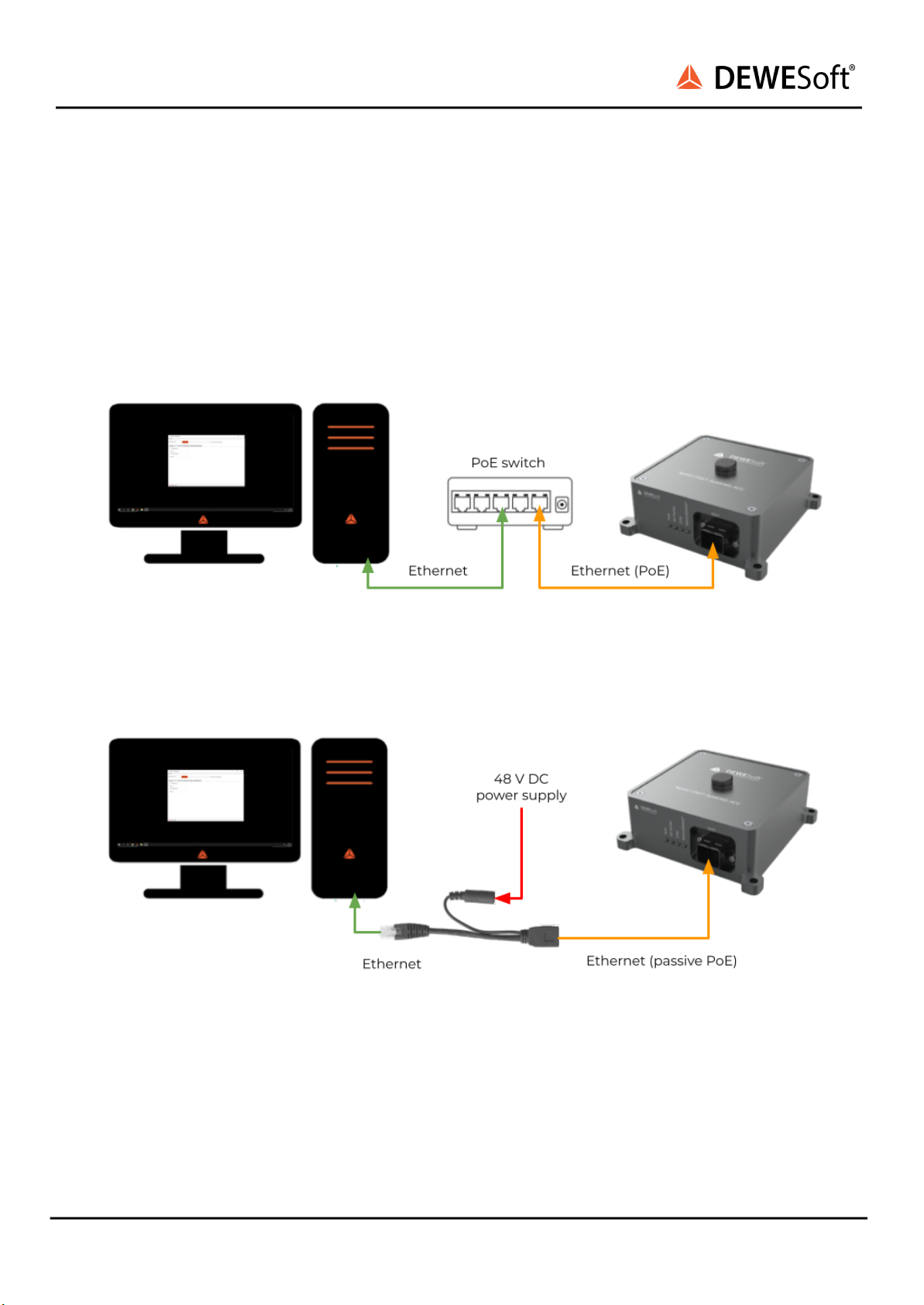
The initial variant of the NEMOSENSE devices released is NEMOSENSE-3xMEMS-ACC. Its physical
interface is PoE (power over ethernet). 3xMEMS-ACC stands for an integrated triaxial MEMS
accelerometer as a measurement front end. The NEMOSENSE platform allows different physical
interfaces and measurement interfaces to be released in future hardware variants.
2. Operational principle
NEMOSENSE is automatically powered up if the power is delivered to the device. On power-up, the
following sequence occurs:
1. Initialization phase - lasts only a few seconds
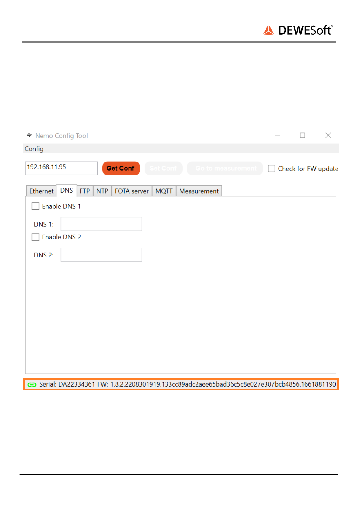
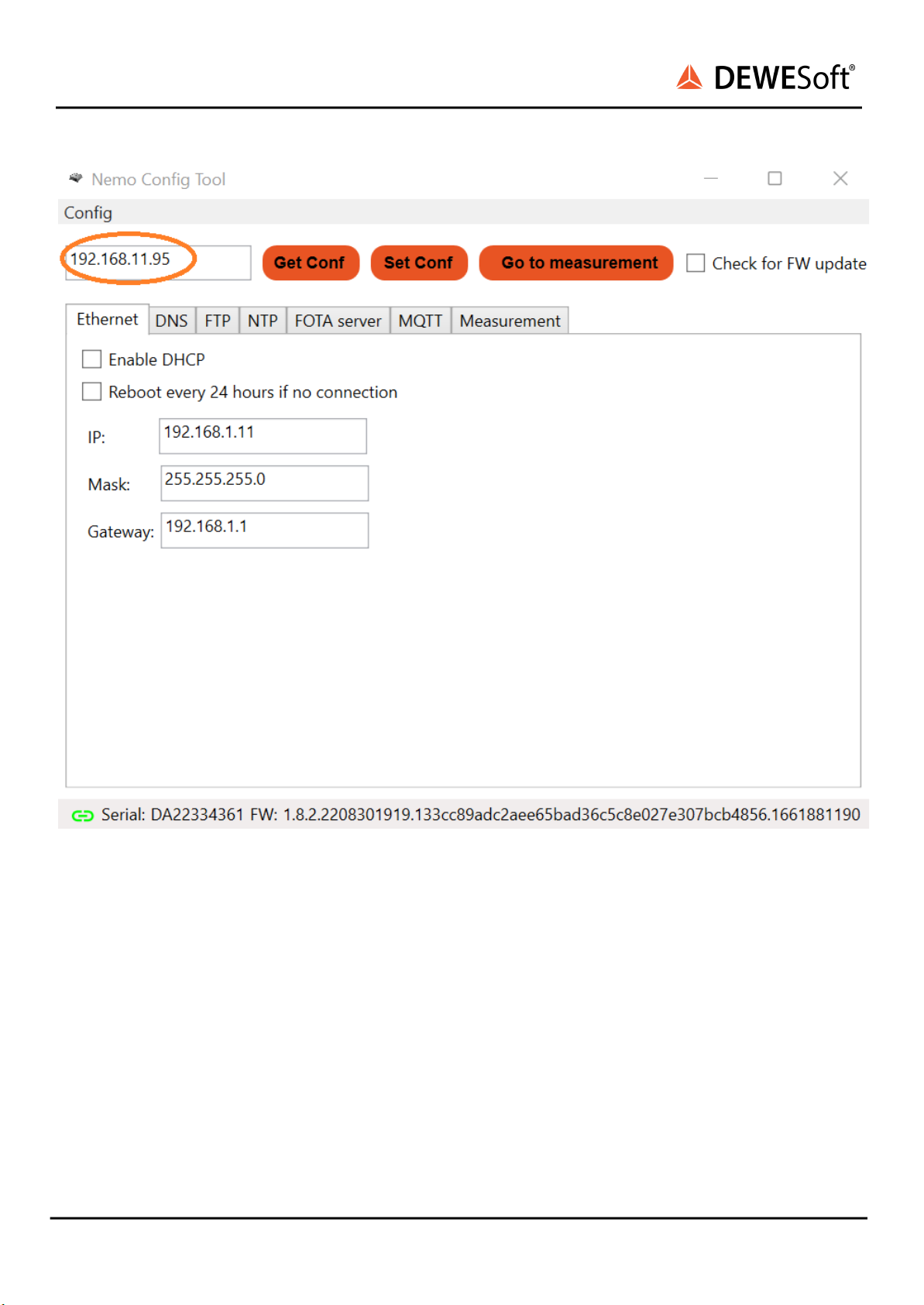
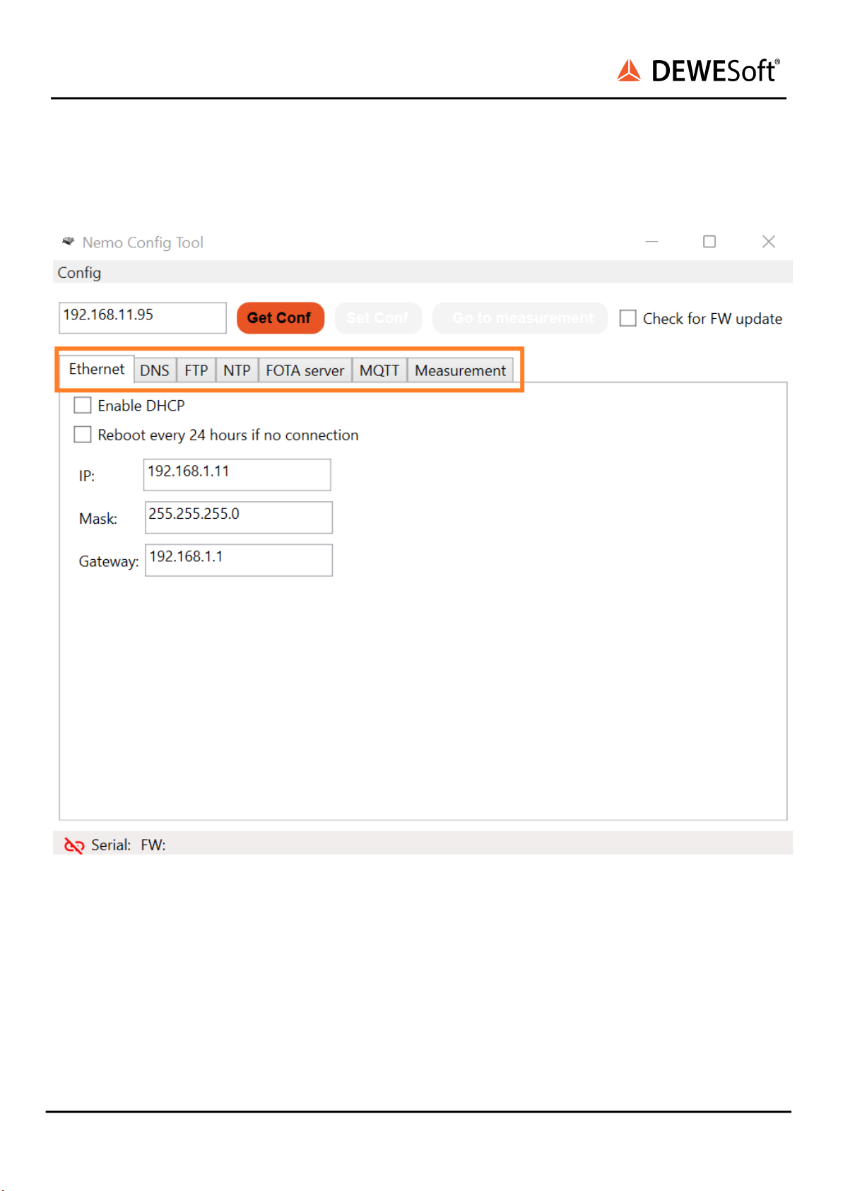
2. Configuration mode - device acts as HTTP server on default IP and can be configured using the
NEMOSENSE Config Tool App.
3. Operational mode - after the configuration is stored the operational mode starts which consists
of the following phases
a. Firmware upgrade mode - device tries to receive a firmware upgrade from the FOTA
server for 60 seconds
b. Measurement mode - the final mode of the start-up sequence and device stays in
measurement mode indefinitely (i.e. until the device receives a restart command from the
MQTT server or there is a power loss)
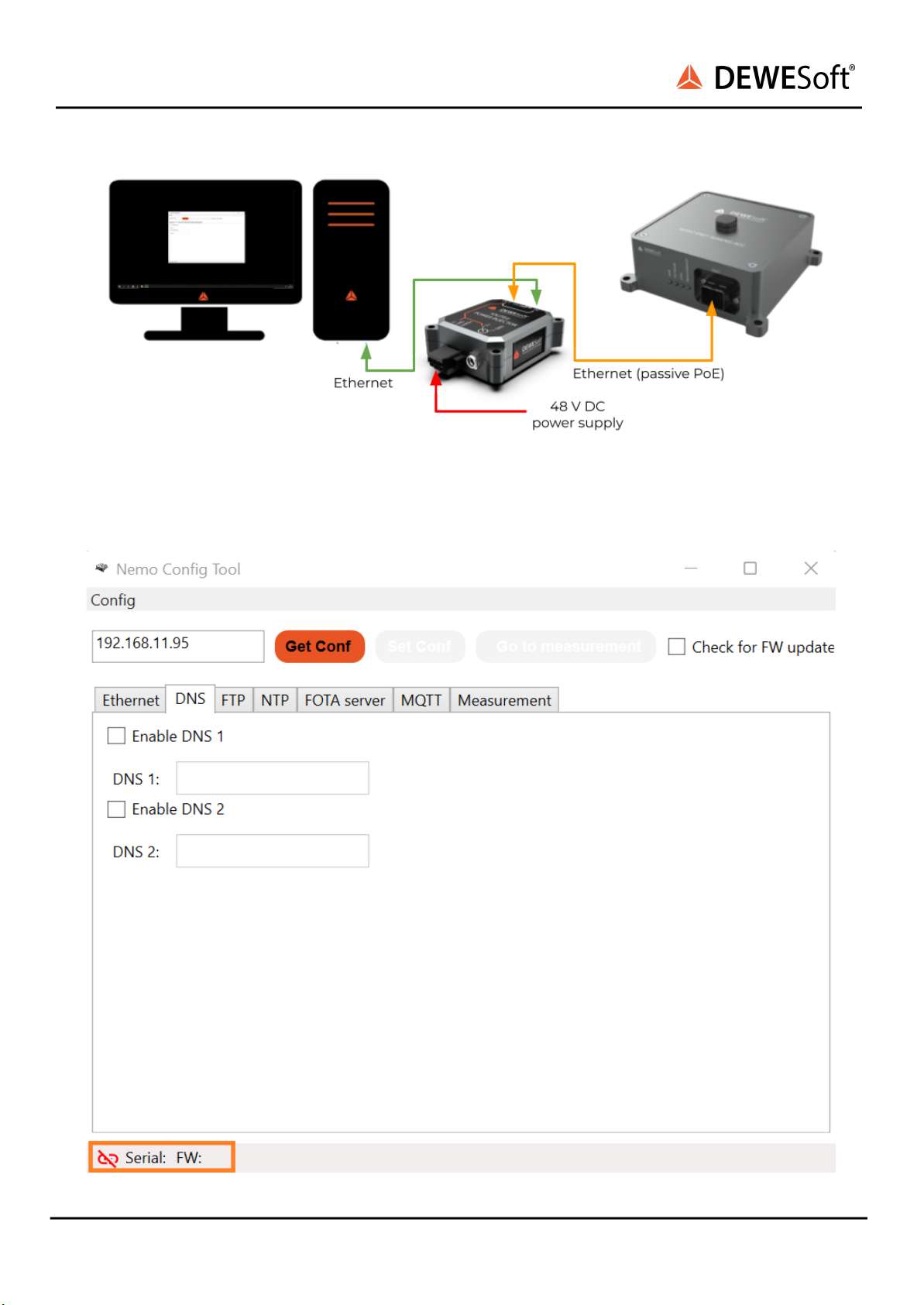
The device can only be interfaced over a TCP/IP network through its sole ethernet port.
NEMOSENSE V23-1 3/23

NEMOSENSE
TECHNICAL REFERENCE MANUAL
3. Getting started with NEMOSENSE
This chapter will help you to install the software, configure your NEMOSENSE device to send the data
over TCP/IP to your or 3rd party server using the Dewesoft Historian software package. We will also show
you how to access the data using Grafana.
To follow the steps, you need the following hardware:
●your NEMOSENSE device
●Your PC
●PoE Switch or a non-powered Ethernet Switch and PoE Injector
●Ethernet CAT6 cable to connect your NEMOSENSE device to your computer for configuration
purposes
And the following software packages:
●The Dewesoft NEMOSENSE Config Tool App
●The Dewesoft Historian software (includes MQTT broker, InfluxDB database an Grafana web GUI)
Dewesoft NEMOSENSE Config Tool App
Download the Dewesoft NEMOSENSE Config Tool App from this link and unzip it.
Dewesoft Historian software
Install the Dewesoft Historian software by following the instructions here
Note: the MQTT client is already running on the NEMOSENSE device, so there is no need to
install it again. Therefore, skip the section: DewesoftX MQTT client.
NEMOSENSE V23-1 4/23

NEMOSENSE
TECHNICAL REFERENCE MANUAL
Configuration mode
Connect your PC to your local network. Connect NEMOSENSE with an Ethernet cable to the same
network over the PoE* Network Switch and run the Dewesoft NEMOSENSE Config Tool App.
*In case you don’t have the PoE Switch you can inject power by using so-called PoE Injectors. 48 V is needed.
Make sure to set the IP address of your PC to the same subnet as the NEMOSENSE default configuration
address (192.168.11.XXX), for example you can set your PC’s IP to: 192.168.11.94 (same subnet but different IP
to the NEMOSENSE device).
Connecting NEMOSENSE to PC over a PoE switch
Connecting NEMOSENSE to PC over a passive PoE injector
NEMOSENSE V23-1 5/23

NEMOSENSE
TECHNICAL REFERENCE MANUAL
Connecting NEMOSENSE to PC over the IOLITE-POWER-INJECTOR
After running the NEMOSENSEConfigApp.exe file, the following screen will appear:
NEMOSENSE V23-1 6/23

NEMOSENSE
TECHNICAL REFERENCE MANUAL
If the device is not in the configuration mode the device serial number and the FW version are NOT
displayed in the bottom left corner (like on the above screenshot). Unplug the device and plug it again to
restart the configuration process.
After the restart the Serial number and the Firmware version should be displayed meaning that the
device is ready to be configured.
To start the configuration and get the latest parameters, press the Get Conf button. After you’ve done
that, the Set Conf and Go to measurement buttons will be enabled.
NEMOSENSE V23-1 7/23

NEMOSENSE
TECHNICAL REFERENCE MANUAL
In the top left corner the static (hard coded) IP of the HTTP server running on the NEMOSENSE device is
displayed. It can only be accessed during configuration mode:
●default configuration HTTP server IP: 192.168.11.95
NEMOSENSE V23-1 8/23

NEMOSENSE
TECHNICAL REFERENCE MANUAL
Note the following tabs in the config tool: Ethernet, DNS, FTP, NTP, FOTA server, MQTT and
Measurement. Those tabs allow you to select the settings of the NEMOSENSE device which will apply
when the device is in measurement mode.
The Ethernet tab offers the ability to set the device to have a static or dynamic (DHCP) IP. It also offers
the possibility to reboot the device every 24 hours if no connection is available.
The DNS tab offers configuration of several DNS servers when the devices are connected to a local
network.
The FTP tab (File transfer protocol) enables the possibility of transferring .csv files over the FTP protocol.
It is a password-protected FTP. It requires the use of a username and password, but the data transfer
itself is not encrypted.
NEMOSENSE V23-1 9/23

NEMOSENSE
TECHNICAL REFERENCE MANUAL
The NTP tab offers the option to have all the devices connected to the same network synchronized to an
NTP server. The IP and the port number of the NTP server need to be defined.
The FOTA server tab (Firmware over the air) it offers the option to update the device firmware remotely.
IP and Port of the FOTA server need to be defined.
The MQTT tab allows the configuration of the MQTT client running on the NEMOSENSE device. The
device communicates with the MQTT broker installed on the server. The functionality can be enabled or
disabled in the NEMOSENSE config tool app. IP and Port of the MQTT broker need to be defined.
The Measurement tab allows the selection of the supported Sample rate (S/s) options. When in
measurement mode, the device continuously acquires the data from the sensor at the specified sample
rate.
Once the settings are properly set press the Set Conf button and then press the Go To Measurement
button. The device will switch from the configuration mode to the operational mode. Configuration of
the device is no longer available.
If you need to reconfigure the device using the Config Tool app, the device needs to be restarted (i.e.
power-cycled) to enter the configuration mode.
NEMOSENSE V23-1 10/23

NEMOSENSE
TECHNICAL REFERENCE MANUAL
Operational mode (measurement)
When the device is in operational mode, the configuration HTTP server is not active anymore. The device
operates as a TCP/IP device with the IP as defined in the Ethernet settings. This can be either a fixed IP or
DHCP.
Connection diagram of NEMOSENSE device in operational / measurement mode
Communication block diagram of NEMOSENSE device in measurement mode connected to Dewesoft
Historian
When in measurement mode, the device continuously acquires the data from the sensor at the
specified sample rate. The data is saved to a data file (.csv) in internal memory every 10 minutes. After
each file is complete, it is sent to the server either over FTP or MQTT.
If the connection to the server is lost, the device will transmit the files when the connection is available.
The oldest files are always transmitted first. The device will gradually transmit all old files and catch up to
transmit the latest files. The files on the internal memory are only overwritten when the memory is full
NEMOSENSE V23-1 11/23

NEMOSENSE
TECHNICAL REFERENCE MANUAL
(with a standard 16 GB memory this occurs after approximately 1 month of measurement at up to 125
S/s).
Synchronization
The device supports NTP synchronization. The devices are synced at production time to the factory NTP
server. Even when powered off, there is a very precise RTC clock on the device that keeps track of the
time. Therefore when the device is powered up again, it will have reasonably accurate absolute time.
If the NTP time is available at the start of the measurement mode (i.e. the device can reach the NTP
server that is configured), it will immediately jump-sync its time to the NTP time and start the
measurement.
If the device cannot reach the NTP server, it will start the measurement without additional
synchronization. If the NTP server is reached later on during the measurement, the device will compare
its time to the NTP time and the following will occur:
●If the time difference is less than 10 seconds, the device will gradually steer its clock to the NTP
time and the measurement will not stop
●It the time difference is more than 10 seconds, the device will restart the measurement in
jump-sync its clock to the NTP time
When the NTP time is available, the device continuously steers its clock to the NTP time. The sync
difference between NEMOSENSE devices on the same network with a local NTP server is typically within
10 ms. This value depends mainly on the latency of the network.
Meaning of LEDs
There are four LEDs on the front panel of the NEMOSENSE device next to the RJ45 connector.
1. RUN LED (orange)
When on, it Indicates that the device is powered and running.
2. NETWORK LED (blue)
The LED communicates an error code by flashing 1-time, 2-times, 3-times etc. according to the
plan below. Example: if there are NTP and FOTA server errors, the LED will flash 3-times, then stay
off for a second, and flash 4-times. The pattern will repeat indefinitely.
a. LED is on: all network functions operate correctly
b. LED flashes once: no TCP/IP connection to the server
c. LED flashes twice: no FTP / MQTT connection to the server
d. LED flashes three times: no NTP connection
e. LED flashes four times: no connection to FOTA server
3. SYNC LED (red)
In normal operation the LED will flash every three seconds. The flash is synced to the absolute
clock of the device. This means that two devices should blink at the same time if they are synced
NEMOSENSE V23-1 12/23

NEMOSENSE
TECHNICAL REFERENCE MANUAL
and the flashing of the SYNC LED can indicate to the user if a group of devices is synced together
or not.
If the SYNC led is ON permanently, this indicates an internal error. Device needs to be
power-cycled and it is strongly suggested that the user contacts Dewesoft support.
4. MEASUREMENT LED (green)
When on, it indicates that the device is measuring and storing the data to the SD card.
NEMOSENSE V23-1 13/23

NEMOSENSE
TECHNICAL REFERENCE MANUAL
4. Specifications
General device specifications: NEMOSENSE
NEMOSENSE
Physical interface
Ethernet
Connector
RJ45 Harting push-pull
Internal storage
16 GB memory
Data file formats
CSV
Data transfer protocols
MQTT, FTP
Device management protocols
MQTT, HTTPS
Synchronization
NTP
Synchronization delay
10 ms (LAN)
Power supply
48 V PoE
Power consumption
1.3 W
Operating temperature
-20..60 °C
Storage temperature
-20..60 °C
IP rating
IP67
Dimensions
119 x 119 x 42 mm
Weight
500 g
Rev: 1593518446
NEMOSENSE V23-1 14/23

NEMOSENSE
TECHNICAL REFERENCE MANUAL
Measurement specifications: 3xMEMS-ACC
NEMOSENSE
3xMEMS-ACC
Min.
Typ.
Max.
Measurement ranges
+-2 g
-3 dB bandwidth at 31.25 S/s
6 Hz
Sample rate
31.25 S/s
125 S/s
Dynamic range
96 dB
Noise density (lowest range)
25 µg/√Hz
Residual noise (+-2 g range, 6 Hz bandwidth)
50 µg RMS
Calibrated offset error
+-4 mg
Calibrated gain error
+-0.2 %
Offset temperature drift (-20 .. 60 degC)
-0.15 mg / degC
+-0.02 mg / degC
0.15 mg / degC
Sensitivity temperature drift (-20 .. 60 degC)
+-0.01 % / degC
Linearity error (smallest range)
0.1 % FS
Crossaxis sensitivity
1 %
NEMOSENSE V23-1 15/23

NEMOSENSE
TECHNICAL REFERENCE MANUAL
Dimensional drawing: NEMOSENSE-3xMEMS-ACC
NEMOSENSE V23-1 16/23

NEMOSENSE
TECHNICAL REFERENCE MANUAL
About this document
This is the users manual for NEMOSENSE device family.
Legend
The following symbols and formats will be used throughout the document.
Important
It gives you important information about the subject.
Please read carefully!
Hint
It gives you a hint or provides additional information about a subject.
Example
Gives you an example of a specific subject.
Online versions
Device Technical Reference Manual
The most recent version of this manual can be downloaded from our homepage:
https://download.dewesoft.com/list/manuals-brochures/hardware-manuals
In the Hardware Manuals section click the download link for the Device® technical reference manual.
DEWESoft® User Manual (Not Yet Supported with NEMOSENSE)
The DEWESoft® User Manual document provides basics and additional information and examples for
working with DEWESoft® and certain parts of the program.
The latest version of the DEWESoft® tutorials can be found here:
https://download.dewesoft.com/list/manuals-brochures/software-manuals
In the Software Manuals section click the download link of the DEWESoft X User Manual entry.
NEMOSENSE V23-1 17/23

NEMOSENSE
TECHNICAL REFERENCE MANUAL
Warranty information
Notice
The information contained in this document is subject to change without notice.
Note:
Dewesoft d.o.o. shall not be liable for any errors contained in this document. Dewesoft MAKES NO
WARRANTIES OF ANY KIND WITH REGARD TO THIS DOCUMENT, WHETHER EXPRESS OR IMPLIED.
DEWESOFT SPECIFICALLY DISCLAIMS THE IMPLIED WARRANTIES OF MERCHANTABILITY AND FITNESS
FOR A PARTICULAR PURPOSE. Dewesoft shall not be liable for any direct, indirect, special, incidental, or
consequential damages, whether based on contract, tort, or any other legal theory, in connection with
the furnishing of this document or the use of the information in this document.
The copy of the specific warranty terms applicable to your Dewesoft product and replacement parts can
be obtained from your local sales and service office. To find a local dealer for your country, please visit
https://dewesoft.com/support/distributors.
Calibration
Every instrument needs to be calibrated at regular intervals. The standard norm across nearly every
industry is annual calibration. Before your Dewesoft data acquisition system is delivered, it is calibrated.
Detailed calibration reports for your Dewesoft system can be requested. We retain them for at least one
year, after system delivery.
Support
Dewesoft has a team of people ready to assist you if you have any questions or any technical difficulties
regarding the system. For any support please contact your local distributor first or Dewesoft directly.
Dewesoft d.o.o.
Gabrsko 11a
1420 Trbovlje Slovenia
Europe Tel.: +386 356 25 300
Web: http://www.dewesoft.com
Email: [email protected]om
The telephone hotline is available Monday to Friday from 07:00 to 16:00 CET (GMT +1:00)
Service/repair
The team of Dewesoft also performs any kinds of repairs to your system to assure a safe and proper
operation in the future. For information regarding service and repairs please contact your local
distributor first or Dewesoft directly on https://dewesoft.com/support/rma-service.
Restricted Rights
Use Slovenian law for duplication or disclosure. Dewesoft d.o.o. Gabrsko 11a, 1420 Trbovlje, Slovenia /
Europe.
NEMOSENSE V23-1 18/23

NEMOSENSE
TECHNICAL REFERENCE MANUAL
Printing History
/
Copyright
Copyright © 2015-2023 Dewesoft d.o.o. This document contains information which is protected by
copyright. All rights are reserved. Reproduction, adaptation, or translation without prior written
permission is prohibited, except as allowed under the copyright laws. All trademarks and registered
trademarks are acknowledged to be the property of their owners.
Trademarks
We take pride in our products and we take care that all key products and technologies are registered as
trademarks all over the world. The Dewesoft name is a registered trademark. Product families (KRYPTON,
SIRIUS, DSI, DS-NET) and technologies (DualCoreADC, SuperCounter, GrandView) are registered
trademarks as well. When used as the logo or as part of any graphic material, the registered trademark
sign is used as a part of the logo. When used in text representing the company, product or technology
name, the ® sign is not used. The Dewesoft triangle logo is a registered trademark but the ® sign is not
used in the visual representation of the triangle logo.
Safety instructions
Your safety is our primary concern! Please be safe!
Safety symbols in the manual
Warning
Calls attention to a procedure, practice, or condition that could cause the body injury or death
Caution
Calls attention to a procedure, practice, or condition that could possibly cause damage to
equipment or permanent loss of data.
General Safety Instructions
Warning
The following general safety precautions must be observed during all phases of operation, service, and
repair of this product. Failure to comply with these precautions or with specific warnings elsewhere in
this manual violates safety standards of design, manufacture, and intended use of the product. Dewesoft
d.o.o. assumes no liability for the customer’s failure to comply with these requirements.
All accessories shown in this document are available as an option and will not be shipped as standard
parts.
NEMOSENSE V23-1 19/23

NEMOSENSE
TECHNICAL REFERENCE MANUAL
Environmental Considerations
Information about the environmental impact of the product.
Product End-of-Life Handling
Observe the following guidelines when recycling a Dewesoft system:
System and Components Recycling
Production of these components required the extraction and use of natural resources. The substances
contained in the system could be harmful to your health and to the environment if the system is
improperly handled at its end of life! Please recycle this product in an appropriate way to avoid
unnecessary pollution of the environment and to keep natural resources.
This symbol indicates that this system complies with the European Union’s requirements
according to Directive 2002/96/EC on waste electrical and electronic equipment (WEEE).
Please find further information about recycling on the Dewesoft web site www.dewesoft.com
Restriction of Hazardous Substances
This product has been classified as Monitoring and Control equipment and is outside the
scope of the 2002/95/EC RoHS Directive. However, we take care of our environment and the product is
lead-free.
General safety and hazard warnings for all Dewesoft systems
Safety of the operator and the unit depend on following these rules.
●Use this system under the terms of the specifications only to avoid any possible danger.
●Read your manual before operating the system.
●Observe local laws when using the instrument.
●DO NOT touch internal wiring!
●DO NOT use higher supply voltage than specified!
●Use only original plugs and cables for harnessing.
●You may not connect higher voltages than rated to any connectors.
●The power cable and connector serve as Power-Breaker. The cable must not exceed 3 meters, the
disconnect function must be possible without tools.
●Maintenance must be executed by qualified staff only.
●During the use of the system, it might be possible to access other parts of a more comprehensive
system. Please read and follow the safety instructions provided in the manuals of all other
components regarding warning and security advice for using the system.
●With this product, only use the power cable delivered or defined for the host country.
●DO NOT connect or disconnect sensors, probes or test leads, as these parts are connected to a
voltage supply unit.
●Ground the equipment: For Safety Class 1 equipment (equipment having a protective earth
terminal), a non-interruptible safety earth ground must be provided from the mains power
source to the product input wiring terminals.
●Please note the characteristics and indicators on the system to avoid fire or electric shocks. Before
connecting the system, please read the corresponding specifications in the product manual
carefully.
NEMOSENSE V23-1 20/23
This manual suits for next models
1
Table of contents
Other DEWESOFT Network Hardware manuals
Popular Network Hardware manuals by other brands

National Instruments
National Instruments USB Digitizers NI USB-5132 user guide

ASUSTOR
ASUSTOR AS-204RS Quick installation guide

Altai Technologies
Altai Technologies A8 installation guide

Crestron
Crestron C2N-NPA8 Operation guide

Seyeon Technology
Seyeon Technology FlexWATCH 5440 user guide

Opengear
Opengear CM4116 quick start guide