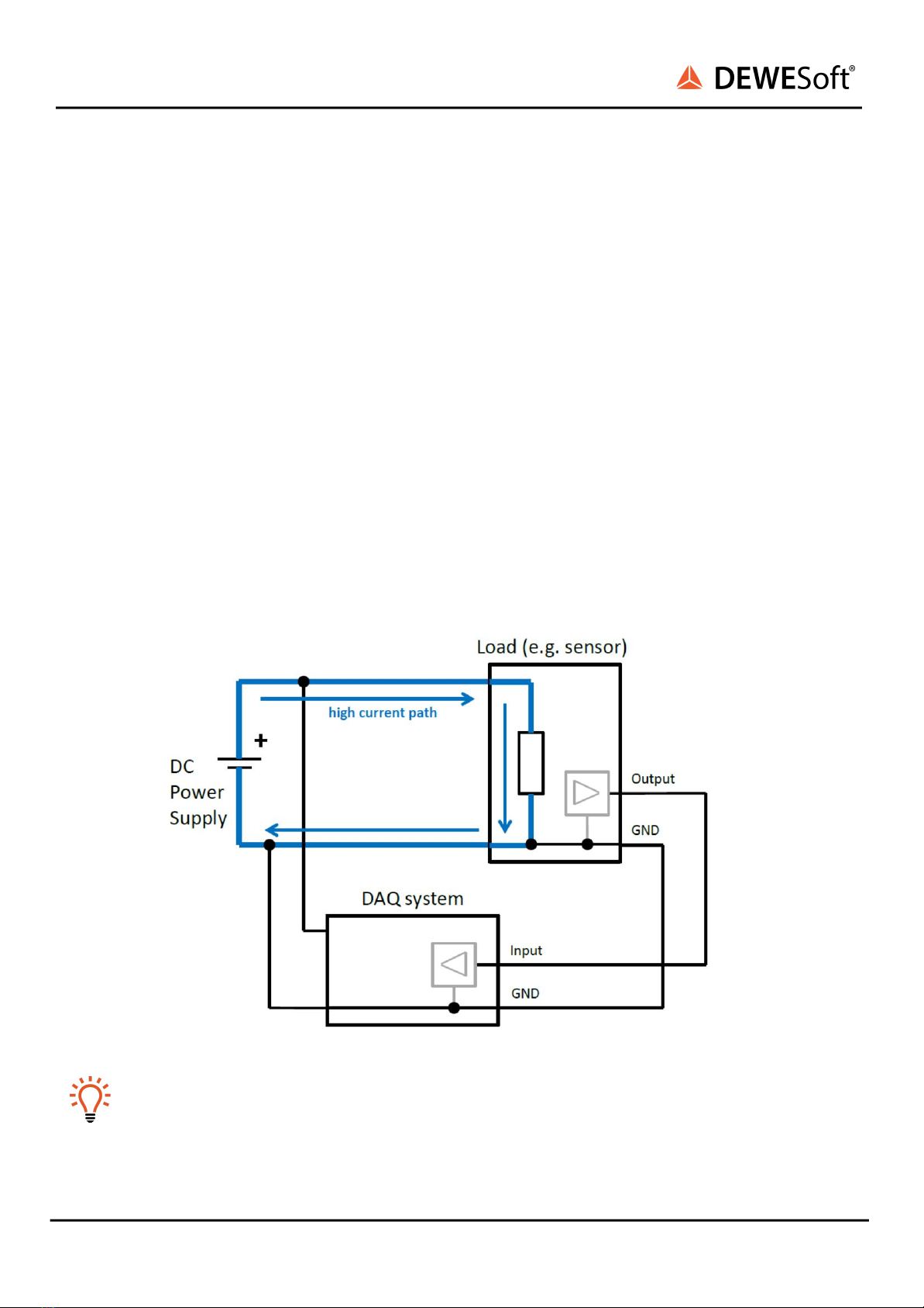
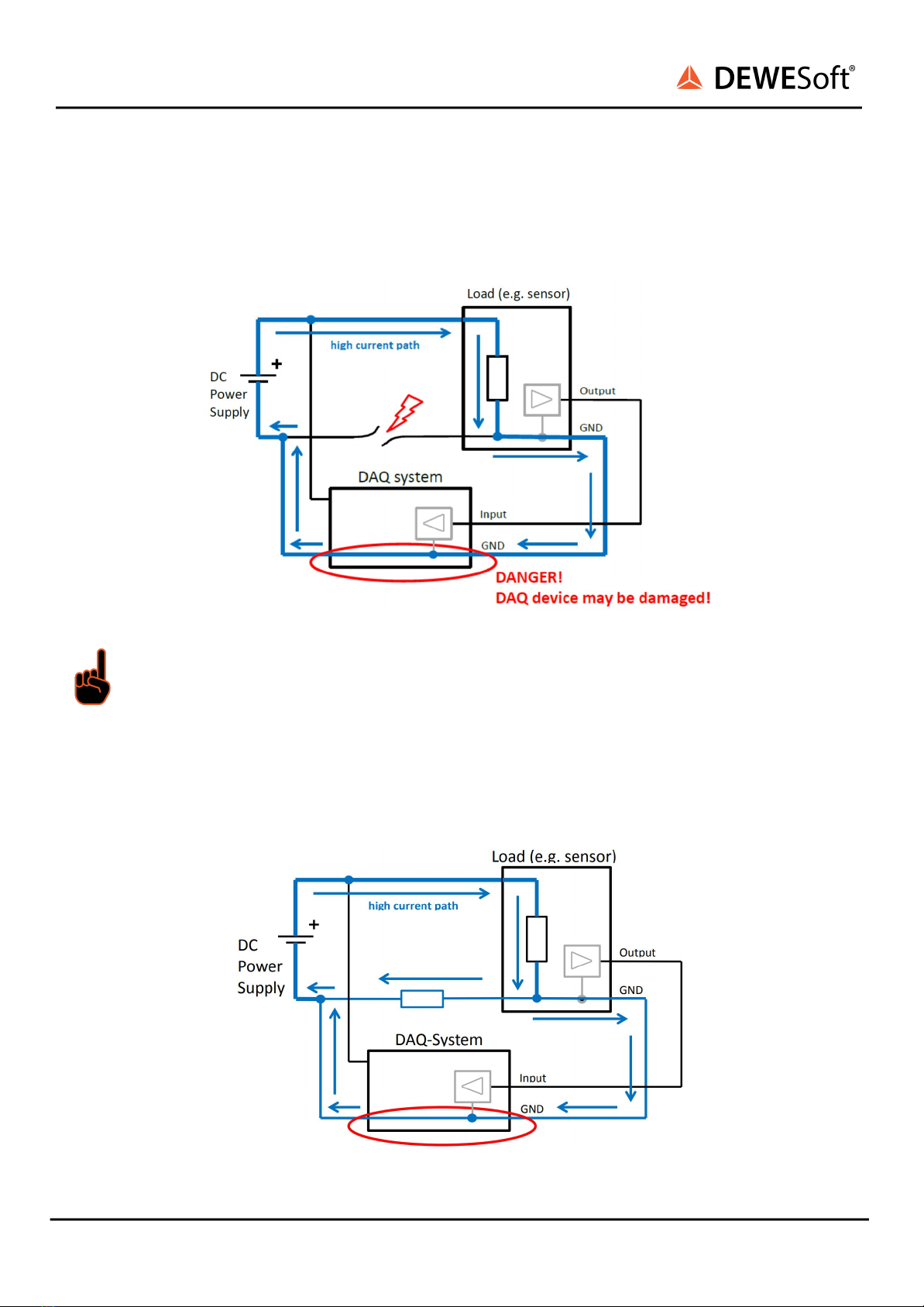
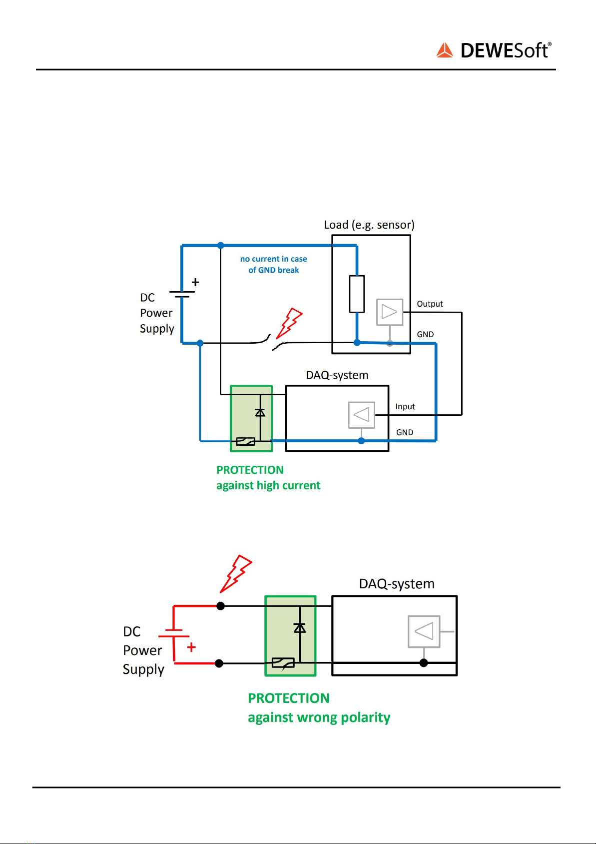
Power supply ground loops
USER MANUAL
Environmental Considerations
Information about the environmental impact of the product.
Product End-of-Life Handling
Observe the following guidelines when recycling a Dewesoft system:
System and Components Recycling
Production of these components required the extraction and use of natural resources. The substances
contained in the system could be harmful to your health and to the environment if the system is
improperly handled at its end of life! Please recycle this product in an appropriate way to avoid
unnecessary pollution of the environment and to keep natural resources.
This symbol indicates that this system complies with the European Union’s requirements
according to Directive 2002/96/EC on waste electrical and electronic equipment (WEEE).
Please find further information about recycling on the Dewesoft web site
www.dewesoft.com
Restriction of Hazardous Substances
This product has been classified as Monitoring and Control equipment and is outside the scope of the
2002/95/EC RoHS Directive. However, we take care of our environment and the product is lead-free.
General safety and hazard warnings for all Dewesoft systems
Safety of the operator and the unit depend on following these rules.
●Use this system under the terms of the specifications only to avoid any possible danger.
●Read your manual before operating the system.
●Observe local laws when using the instrument.
●DO NOT touch internal wiring!
●DO NOT use higher supply voltage than specified!
●Use only original plugs and cables for harnessing.
●You may not connect higher voltages than rated to any connectors.
●The power cable and connector serve as Power-Breaker. The cable must not exceed 3 meters,
the disconnect function must be possible without tools.
●Maintenance must be executed by qualified staff only.
●During the use of the system, it might be possible to access other parts of a more comprehensive
system. Please read and follow the safety instructions provided in the manuals of all other
components regarding warning and security advice for using the system.
●With this product, only use the power cable delivered or defined for the host country.
●DO NOT connect or disconnect sensors, probes or test leads, as these parts are connected to a
voltage supply unit.
●Ground the equipment: For Safety Class 1 equipment (equipment having a protective earth
terminal), a non-interruptible safety earth ground must be provided from the mains power
source to the product input wiring terminals.
●Please note the characteristics and indicators on the system to avoid fire or electric shocks.
Before connecting the system, please read the corresponding specifications in the product
manual carefully.
V20-1 10/12