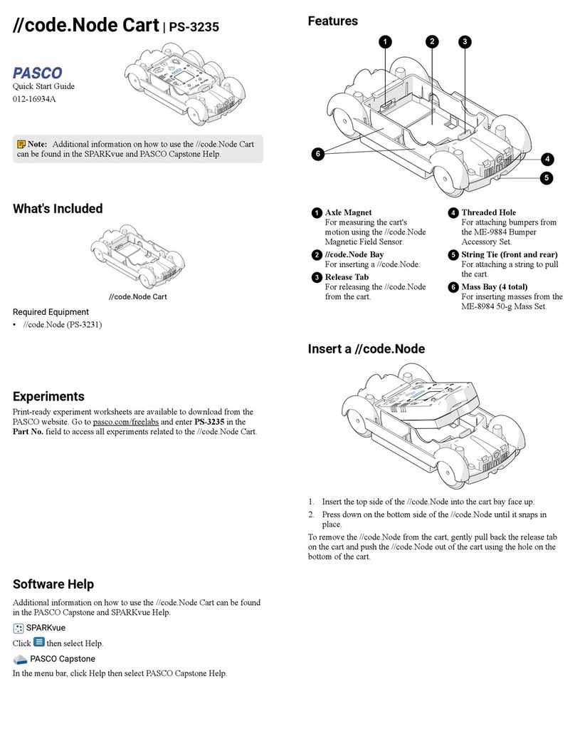
DEWESOFT VIBRO KIT V20-2 Product manual

VIBRO KIT
TECHNICAL REFERENCE MANUAL
VIBRO KIT V20-2

VIBRO KIT
TECHNICAL REFERENCE MANUAL
1 Table of contents
1 Table of contents 2
2 About this document 4
2.1 Legend 4
3 Technical data 5
3.1 Introduction 5
3.2 Scope of supply 5
3.3 Vibro-kit parts description 6
3.3.1 Encoders 6
3.3.2 Optical sensor below taped disk 7
3.3.3 Front panel 8
3.3.4 Back panel 9
3.3.5 Couplings 11
4 Possibilities of use 12
4.1 Super-counters 12
4.2 FFT analyzer 15
4.3 Order tracking 17
4.4 Balancing 18
4.5 Torsional vibration 20
5 Specifications HW v1.3 22
6 User interface FW v1.9 22
6.1 Manual mode 22
6.2 Ramp mode 23
6.3 Analog in mode 24
6.4 PWM in mode 24
7 Warranty information 25
7.1 Calibration 25
7.2 Support 25
7.3 Service/repair 25
7.4 Restricted Rights 25
7.5 Printing History 26
7.6 Copyright 26
7.7 Trademarks 26
8 Safety instructions 26
8.1 Safety symbols in the manual 26
8.2 General Safety Instructions 26
8.2.1 Environmental Considerations 27
8.2.2 Product End-of-Life Handling 27
8.2.3 System and Components Recycling 27
8.2.4 General safety and hazard warnings for all Dewesoft systems 27
VIBRO KIT V20-1 2/29

VIBRO KIT
TECHNICAL REFERENCE MANUAL
2 About this document
2.1 Legend
The following symbols and formats will be used throughout the document.
Important
It gives you important information about the subject.
Please read carefully!
Hint
It gives you a hint or provides additional information about a subject.
Example
Gives you an example of a specific subject.
VIBRO KIT V20-1 4/29

VIBRO KIT
TECHNICAL REFERENCE MANUAL
3 Technical data
3.1 Introduction
The new VIBRO-KIT is a compact tool for simulating rotating machinery measurements. It is meant for
demonstrations or educational purposes such as in a lab or university. It provides a playground for
almost unlimited experiments.
It's made of solid aluminum. It’s built of a small electric motor with a simple control panel, two bearings,
two optical strip-tape angle sensors, two encoders and two different couplings on each side. One is rigid
and the other is made of spring.
The RPM can be controlled manually by a turn knob, or you can completely define ramps, cycles, etc.
with the built-in display.
Furthermore, an external analog voltage (or even PWM signal) can be used to control the RPM.
Functionalities:
●Manual RPM control (turn knob, display)
●Definable ramps (runup, coast down, hold time and multiple cycles)
●RPM control by external voltage (e.g. step curve)
●External PWM input
●Different angle sensors (2 optical strip tape, 2 Encoders)
3.2 Scope of supply
Type
Quantity
Description
Vibro-kit
1
Vibro-kit unit
BNC-BNC
1
BNC to BNC connector cable of 1,2 m
L1B7m-BNC
2
7 pin LEMO to BNC connector cable of 0,6 m
BALANCING SCREWS
kit
Screws 10pcs M3x4, 10pcs M3x6, 10 pcs M3x8, 10pcs M3x10
Nuts 20pcs M3x2.3
** Power supply adapter is not included
VIBRO KIT V20-1 5/29

VIBRO KIT
TECHNICAL REFERENCE MANUAL
3.3 Vibro-kit parts description
3.3.1 Encoders
Using projection below the left side refers to the Tacho 1 output signal and right side refers to the Tacho
2 output signal.
Image 1: Vibro-kit unit
Counter input connectors on cable
Pin
Name
Description
1
IN0/A
Output A
2
IN1/B
Output B
3
IN2/Z
Output Z
4
GND
Ground
5
+5V
5V supply
6
+12V
12V supply
7
GND
Ground
VIBRO KIT V20-1 6/29

VIBRO KIT
TECHNICAL REFERENCE MANUAL
3.3.2 Optical sensor below taped disk
Integrated optical sensor on the bottom side of the chassis for measuring signal of the striped tape on
the rotating disc which is affixed on the shaft of the motor.
Please see chapter 3.3.1. Encoders to define which sensor has Tacho 1 output and which has Tacho 2
output.
Image 2: Vibro-kit unit
VIBRO KIT V20-1 7/29

VIBRO KIT
TECHNICAL REFERENCE MANUAL
3.3.3 Front panel
Button on the top serves as a ON/OFF start button for the motor. The front knob serves as a navigation
knob for the Menu. Display shows general values and motor options when Vibro-kit is turned on.
Image 3: Front panel of drive part
VIBRO KIT V20-1 8/29

VIBRO KIT
TECHNICAL REFERENCE MANUAL
3.3.4 Back panel
Image 4: Back panel of drive part
Power supply connector
Pin
Name
Description
1
V +
Power supply 12V...36V
2
V -
Ground
VIBRO KIT V20-1 9/29

VIBRO KIT
TECHNICAL REFERENCE MANUAL
Control IN connector
BNC female connector
Using an input signal if you want to control the
RPM of an internal motor with voltage signal.
Tacho 1 Out
BNC female connector
Measuring an output signal from an optical
sensor that is integrated below the rotating disk.
Tacho 2 Out
BNC female connector
Measuring an output signal from an optical
sensor that is integrated below the rotating disk.
VIBRO KIT V20-1 10/29

VIBRO KIT
TECHNICAL REFERENCE MANUAL
3.3.5 Couplings
The right encoder is connected to the spring coupling which damps high accelerations but may cause
an oscillation until the moving parts are equalized.
Black round plate has a white dotted strap on it which you can read with the tacho sensor.
Image 5: Flexible coupling on the right side
The left encoder is connected to the rigid coupling which eliminates any oscillations in regard to the
accelerating.
Image 6: Rigid coupling on the left side
VIBRO KIT V20-1 11/29

VIBRO KIT
TECHNICAL REFERENCE MANUAL
4 Possibilities of use
4.1 Super-counters
Additional equipment: SIRIUS with at least one CNT module (ACC+, …).
DewesoftX’s super-counters work on a 102.4 MHz internal time base, always, independent of the current
sample rate. In comparison to standard counters, which only output whole numbers like 1,1,2,2,3,4, … one
sample later, DewesoftX ® is able to extract the accurate values like 1.37, 1.87, 2.37, … fully time- and
amplitude-synchronized. This is done by measuring the exact time of the rising edge of the signal with
an additional counter.
Image 7: Super-counter
Frequency/super-counter mode has many advantages over traditional counter measurements.
The problem with traditional counters is that the value of the counter is latched only at a sample rate
interval. Therefore, we only have discrete values on each sample. Since the counters can measure exactly
where the position of the pulse is between two samples, we can calculate two things out of this: the
exact interpolated position of the counter at the sample point, as well as the exact frequency of the
pulses.
We connect the encoder to the CNT module. In DewesoftX ® software, we add the Counters.
VIBRO KIT V20-1 12/29

VIBRO KIT
TECHNICAL REFERENCE MANUAL
Image 8: Counters
In the Counter menu, you will see all the available counter channels. Enter the setup of the channel
where your encoder is connected.
Change the Basic application to the Sensor and choose the correct sensor from the dropdown list. If
your sensor is not on the list, you can add it in the counter sensor editor.
Select the output channels that you want to show (angle, frequency, raw count).
VIBRO KIT V20-1 13/29

VIBRO KIT
TECHNICAL REFERENCE MANUAL
Image 9: Counter menu
Enter the Measure mode and add a recorder visual control. Display the Angle and Raw count on the
same recorder. When the Vibro Kit is running, press Freeze and zoom into the signal. You can see how
DewesoftX ® interpolates the angle values and is not updated only when a new pulse comes from the
angle sensor. The raw count value is increased every time a new pulse comes from the sensor.
VIBRO KIT V20-1 14/29

VIBRO KIT
TECHNICAL REFERENCE MANUAL
Image 10: Signals on recorder
For more detailed explanation of the parameters, please visit:
https://training.dewesoft.com/online/course/digital-counters
4.2 FFT analyzer
Additional needed equipment: SIRIUS with one ACC, accelerometer.
Glue the accelerometer on the Vibro Kit. Connect the accelerometer to the SIRIUS ACC module, and
enter the channel setup. Select the IEPE mode – if the sensor has a TEDS chip, the sensitivity will be
recognized. Otherwise, enter the setup and change the sensitivity of the sensor manually.
Image 11: Channel setup
Add the FFT analyzer math module (with the click on the plus button More). Select the input channel
(accelerometer) and set up the math.
VIBRO KIT V20-1 15/29

VIBRO KIT
TECHNICAL REFERENCE MANUAL
Image 12: FFT analyser settings
Enter the measure mode and add the FFT channel on a 2D graph. Run the machine and observe the
FFT.
Image 13: FFT math on 2D graph
VIBRO KIT V20-1 16/29

VIBRO KIT
TECHNICAL REFERENCE MANUAL
On the FFT graph, you can show the markers and how FFT behaves with different parameters in the
setup. For an explanation of all the parameter visit:
https://training.dewesoft.com/online/course/fft-spectral-analysis
4.3 Order tracking
Additional needed equipment: SIRIUS with one ACC and one CNT module, accelerometer.
Glue the accelerometer on the Vibro Kit and connect it to the ACC module. Connect encoder to the CNT
module. Open channel setup and set the acceleration sensor to IEPE mode and enter the correct
sensitivity. Add an Order tracking module.
Image 14: Order tracking settings
Select the vibration and the frequency input channel. Detailed description of all the parameters can be
found here: https://training.dewesoft.com/online/course/order-tracking
Enter the measure mode, and run the machine slowly from 0 RPM to 3000 RPM.
VIBRO KIT V20-1 17/29

VIBRO KIT
TECHNICAL REFERENCE MANUAL
The order tracking module creates a display with two 3D graphs to show order and FFT waterfalls, two
2D graphs to show the order harmonics and phase of the harmonics and a digital meter to monitor the
RPMs of the machine.
Image 15: Order tracking screen
4.4 Balancing
Additional needed equipment: SIRIUS with one ACC (single plane balancing) or two ACC modules (dual
plane balancing), accelerometer (single plane balancing) or two accelerometers (dual plane balancing),
additional screws for balancing the rotor.
Select the input channel (vibration) and define the frequency source (counters, analog sensor, RPM
channel). Balancing procedures should be done at constant RPMs.
VIBRO KIT V20-1 18/29

VIBRO KIT
TECHNICAL REFERENCE MANUAL
Image 16: Balancing settings
Balancing is a step-by-step procedure. First, you need to perform the initial run, to get the initial
unbalance vector. After that, you attach a trial weight, perform a trial run to get another unbalance
vector. From those two unbalanced vectors, we calculate the correction mass that has to be added and
the angle at which this should be added. You can perform as many steps as you wish.
Image 17: Rotor balancer screen
For more detailed explanation of balancing parameters and settings, please visit:
https://training.dewesoft.com/online/course/balancing
VIBRO KIT V20-1 19/29

VIBRO KIT
TECHNICAL REFERENCE MANUAL
4.5 Torsional vibration
Additional needed equipment: SIRIUS with 2 CNT modules and accelerometer.
Connect two angle sensors to SIRIUS. Add a torsional vibration module. Select the first (reference) and
second angle sensor input and assign sensors to the counter channels.
Select the wanted output channel from the module. Detailed description of the parameters and setting
can be found here: https://training.dewesoft.com/online/course/rotational-and-torsional-vibration
Image 18: Torsional vibration settings
Enter the measure mode. The plugin creates a new display with 2 XY recorders for displaying the
rotational angles and torsional angle against the reference angle sensor.
On the time recorder, you can see the behavior of the rotational angle and observe how the vibrations
change with the RPM.
VIBRO KIT V20-1 20/29
Table of contents
Other DEWESOFT Science Education Product manuals

