DEWESOFT DC-CT Product manual

DC-CT sensors
TECHNICAL REFERENCE MANUAL
DC-CT V23-1
1

DC-CT
TECHNICAL REFERENCE MANUAL
Table of contents
1. About this document 4
1.1. Legend 4
1.2. Online versions 4
1.2.1. Device Technical Reference Manual 4
1.2.2. DEWESoft® User Manual 4
2. Safety instructions 5
3. Getting started 5
3.1. Software installation 5
3.2. Connecting standalone DC-CT® unit 6
3.2.1. List of required equipment: 6
3.2.2. Wiring 7
3.2.3. Powering the unit 7
4. Product overview 8
4.1. Main features 8
4.2. The DC-CT technology 9
4.2.0.1. A brief comparison of different current measurement technologies 10
5. DC-CT Sensors 11
5.1. DC-CT-1000I-S22DA 11
5.1.1. DC-CT-1000I-S22DA: Specifications 12
5.1.2. DC-CT-1000I-S22DA: Technical drawing 14
5.1.3. DC-CT-1000I-S22DA: Pinout 15
5.1.3.1. DC-CT-1000I-S22DA: Pinout: D9 connector 15
5.1.4. DC-CT-1000I-S22DA: Characteristics 16
5.1.4.1. Accuracy 16
5.1.4.2. Off-Center Error 17
5.1.4.3. A Peak-to-Peak Cycling Test 18
1.1.4 AC Response 18
5.1.4.4. Temperature Drift 19
5.1.4.4.1. Offset Drifting 19
5.1.4.5. Noise 20
5.1.4.5.1. kHz Bandwidth Noise 20
5.1.4.5.2. MHz Bandwidth Noise and Ripple 20
5.2. DSI adapters 22
5.2.1. DSI-DC-CT-1000I-0.3m 22
5.2.1.1. DSI-DC-CT-1000I-0.3m: Specifications 22
5.2.1.2. DSI-DC-CT-1000I-0.3m: Pinout 23
5.2.1.3. DSI-DC-CT-1000I-0.3m: Characteristics 24
5.2.1.3.1. Magnitude response 24
5.2.1.3.2. Phase response 24
6. Warranty information 26
6.1. Calibration 26
6.2. Support 26
6.3. Service/repair 26
6.4. Restricted Rights 26
6.5. Printing History 27
6.6. Copyright 27
6.7. Trademarks 27
DC-CT V23-1 2/30

DC-CT
TECHNICAL REFERENCE MANUAL
7. Safety instructions 27
7.1. Safety symbols in the manual 27
7.2. General Safety Instructions 27
7.2.1. Environmental Considerations 28
7.2.2. Product End-of-Life Handling 28
7.2.3. System and Components Recycling 28
7.2.4. General safety and hazard warnings for all Dewesoft systems 28
7.3. Documentation version history 30
DC-CT V23-1 3/30

DC-CT
TECHNICAL REFERENCE MANUAL
1. About this document
This is the Technical Reference Manual for DC-CT Sensors Version V23-1
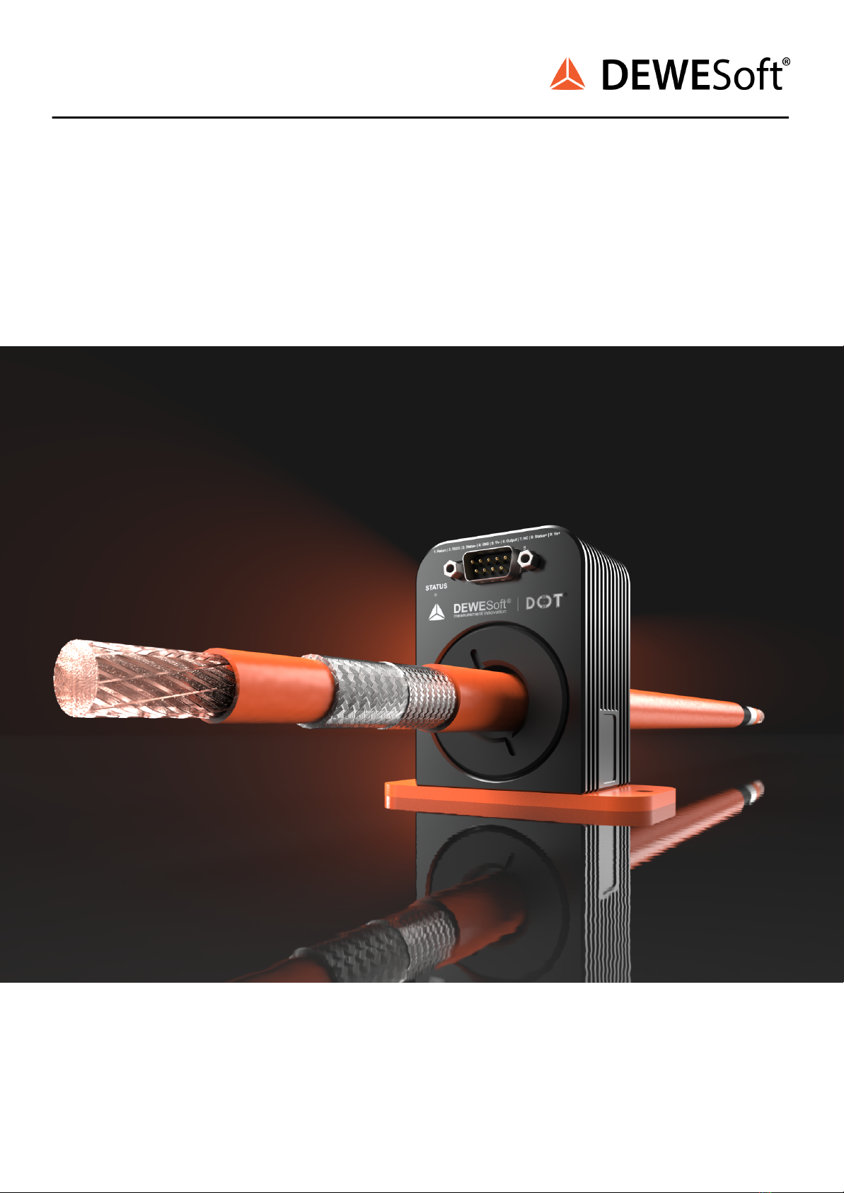
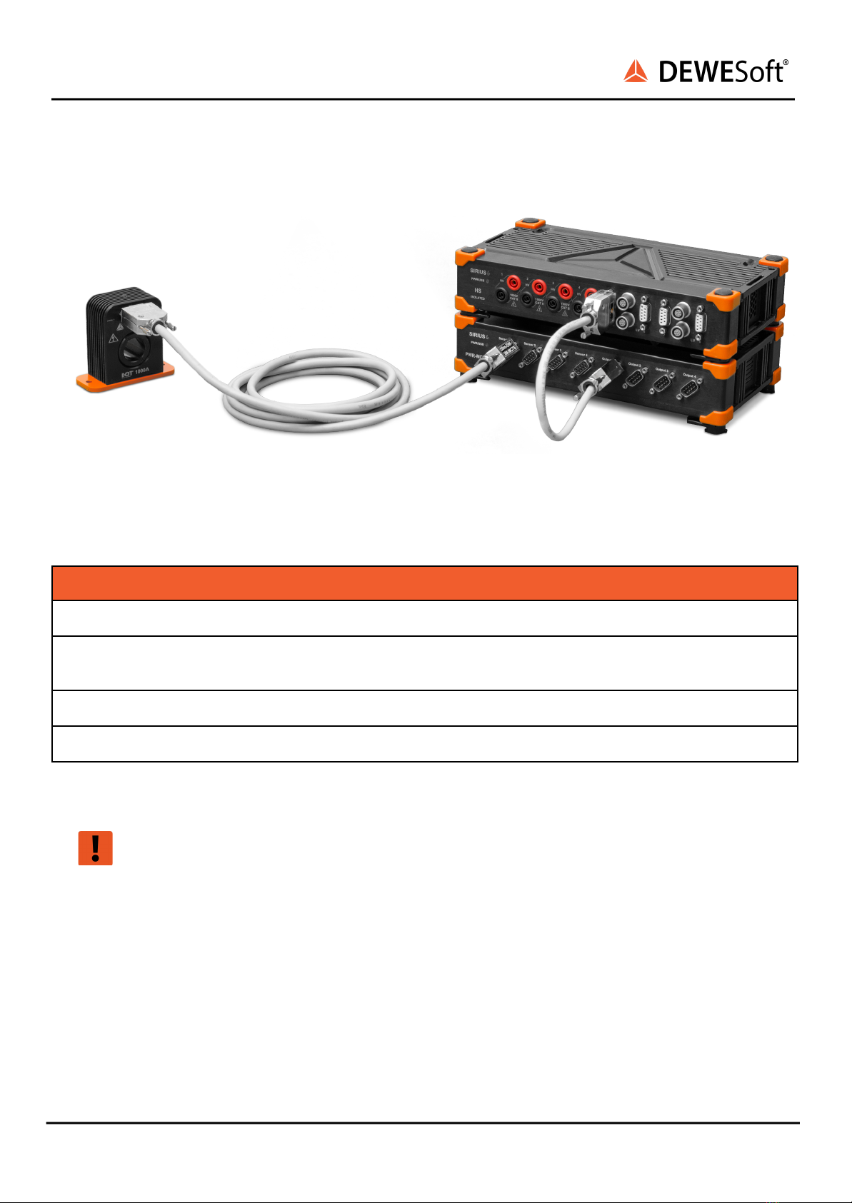
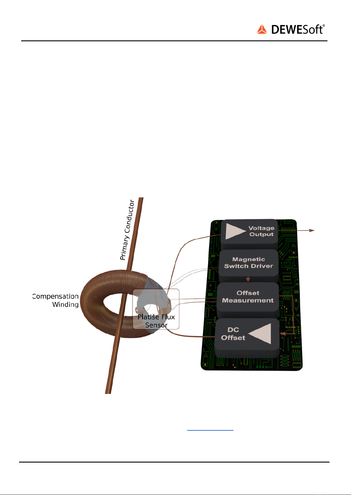
DC-CT is a high-performance, low-power consumption current transducer, specially designed in a
smaller housing than usual for easier mounting in E-mobility applications where enough space is usually
an issue. Together with our measurement devices and power supply, it represents a high-speed,
accurate and precise solution for current measurements of your choice.
The manual is divided into several chapters. You will find:
●A detailed description of the DC-CT current transducers
●A detailed description of the DC-CT accessories
●A description of the patented technology used for measurement
●A comprehensive introduction to the configuration of the modules using DewesoftX®
●Detailed technical data and electrical characteristics
1.1. Legend
The following symbols and formats will be used throughout the document.
Important
It gives you important information about the subject.
Please read carefully!
Hint
It gives you a hint or provides additional information about a subject.
Example
Gives you an example of a specific subject.
1.2. Online versions
1.2.1. Device Technical Reference Manual
The most recent version of this manual can be downloaded from our homepage:
https://dewesoft.com/download/manuals
In the Hardware Manuals section click the download link for the Device® technical reference manual.
1.2.2. DEWESoft® User Manual
The DEWESoft® User Manual document provides basics and additional information and examples for
working with DEWESoft® and certain parts of the program.
The latest version of the DEWESoft® tutorials can be found here:
https://dewesoft.com/download/manuals
In the Software Manuals section click the download link of the DEWESoft X User Manual entry.
DC-CT V23-1 4/30

DC-CT
TECHNICAL REFERENCE MANUAL
2. Safety instructions
Your safety is our primary concern! Please be safe!
3. Getting started
This chapter will help you install the software, connect your SIRIUSi system to the PC via USB and show
you how to configure DewesoftX®.
To follow these steps, you need the following items:
●your brand new DC-CT sensor (included in the shipment)
●a DC-CT power supply SIRIUSi-PWR-MCTS2, SIRIUSir-PWR-MCTS2 or SIRIUSir-HD-PWR-MCTS2
●a SIRIUS device with LV, STG, STGS or UNI channel
●your PC with Windows 10/11 (older versions like Windows® 7 may also work)
3.1. Software installation
For optimal working, we recommend that you install the latest version of Dewesoft. If you already have
installed the older version Dewesoft is recommended that you find the newest version on the website
under the Support/Downloads/DewesoftX section. You can also check if a newer version is available in
the software.
Check for update
DC-CT V23-1 5/30

DC-CT
TECHNICAL REFERENCE MANUAL
3.2. Connecting standalone DC-CT® unit
DC-CT connection
3.2.1. List of required equipment:
Function
Dewesoft order code
Power supply for the system
PS-120-L1B2f (default), L1B2f-BAN-Xm
Power supply for the sensor
SIRIUSi-PWR-MCTS2 / SIRIUSir-PWR-MCTS2,
D9m-D9f-Xm-MCTS
DSI adapter for current transducer
DSI-DC-CT-1000-0.3M
Measurement device
Any DEWESoft device with LV, STG, STGS or UNI channel
You can connect up to 4 DC-CT sensors within one system.
Warning
Never operate the DC-CT transducers without power supply (SIRIUSi-PWR-MCTS2,
SIRIUS_ir-PWR-MCTS2). The DC-CT transducer can be damaged!
DC-CT V23-1 6/30

DC-CT
TECHNICAL REFERENCE MANUAL
3.2.2. Wiring
1. Use DSI-DC-CT-1000-0.3M to connect the SIRIUS amplifier to SIRIUSi-PWR-MCTS2. Connect the
male DB9 connector of the DSI cable to the SIRIUS amplifier and the female DB9 connector to
the MCTS device.
Important
Do NOT connect the male DB9 connector of the DSI cable to the female connector on the
MCTS device. In this case TEDS chip will be damaged!
2. Use D9m-D9f-Xm-MCTS to connect your DC-CT sensor to the SIRIUS-PWR-MCTS2 device.
Connect the male DB9 connector of the cable to the MCTS device and the female DB9 connector
to your DC-CT sensor.
3.2.3. Powering the unit
Power supply can be either:
1. bipolar: pin 9 (15 V), pin 5 (-15 V) and pin 4 (0 V) or
2. unipolar: pin 9 (30 V) and pin 5 (0 V)
Important
For best CMRR performance units should be earthed via the screw on the bottom or
back-plate. Note that the D-SUB connector is also grounded, but may create a ground loop
with the chassis. So make sure if the chassis is grounded, that the cable of the D-SUB
connector is not grounded.
DC-CT V23-1 7/30

DC-CT
TECHNICAL REFERENCE MANUAL
4. Product overview
4.1. Main features
The DC-CT-1000I-S22DA is a compact and accurate 1000 A zero-flux current transducer based on ISOTEL
proprietary technology and patented Platiše Flux Sensor (PFS).
Features a typical D-SUB connector with 22 mm opening in Aluminium chassis delivering 500 kHz of flat
bandwidth, 100 ppm linearity, and total offset including hysteresis below 100 ppm FS. Low standby
power consumption of 0.5 W with flexible unipolar/bipolar power supply and differential current output.
●EASY MOUNTING WITH PRECISE MEASUREMENTS: single gap-less high-permeability
core design, compact implementation of very high current sensors,
●MADE FOR HARSH ENVIRONMENTS: excellent immunity to external magnetic fields
due to compact gap-less design, good temperature stability, a property of PFS.
●HIGH BANDWIDTH: wide and flat bandwidth due to good coupling between primary
and secondary side,
●VERY LOW OFFSET: due to compact implementation and gap-less design
●LOW POWER CONSUMPTION: high sensitivity at low power consumption,
●TYPICAL APPLICATIONS: Test and Measuring Equipment, DC and AC Metering, Power
Quality Analysis in Mains, Stable Precision Power Supplies, Battery Management
Systems • Electrical Vehicle Chargers
DC-CT V23-1 8/30

DC-CT
TECHNICAL REFERENCE MANUAL
4.2. The DC-CT technology
The DC-CT technology at its core consists of a high-permeability core and a zero-flux closed-loop null
method measurement principle, using the innovative Platiše Flux Sensor (PFS) zero-flux sensor.
The DC-CT-1000I in addition comprises zero-flux, or null method to achieve highest accuracy and
compensates non-linearities caused by the magnetic material, in similar way as other closed-loop DC-CT
sensors. Key blocks of the Platiše Flux Sensor are represented in the image below.
The primary current flows through the magnetic core wound by a secondary compensating winding of
N turns, defining a current transformation ratio. To a small part of the magnetic core additional
modulating winding, driven by magnetic switch driver, and sensing winding, sensed by offset
measurement circuitry, are added. The residual flux is added to the output amplifier to compensate the
DC component, while the AC component of the DC-CT basically passes through the sensor, directly to
the output
DC-CT technology schematics
More information about the technology can be found at www.dc-ct.com.
DC-CT V23-1 9/30

DC-CT
TECHNICAL REFERENCE MANUAL
4.2.0.1. A brief comparison of different current measurement technologies
The table below summarizes the key features across different technologies:
Technology
Type
Isolated
Current
range
AC
Bandwidth
Linearity
Accuracy
DC-CT
DC/AC
Yes
High
High
Excellent
Very High
Flux-Gate
DC/AC
Yes
High
High
Excellent
Excellent
Hall
DC/AC
Yes
High
Medium
Medium
Medium
Shunt
DC/AC
No
Medium
Medium
Good
High
Rogowsky
AC
Yes
High
High
Goof
Medium
CT
AC
Yes
High
Medium
Medium
Medium
DC-CT V23-1 10/30

DC-CT
TECHNICAL REFERENCE MANUAL
5. DC-CT Sensors
5.1. DC-CT-1000I-S22DA
DC-CT-1000I-S22DA: front
DC-CT-1000I-S22DA: back
DC-CT V23-1 11/30

DC-CT
TECHNICAL REFERENCE MANUAL
5.1.1. DC-CT-1000I-S22DA: Specifications
DC-CT-1000I-S22DA
Type
Zero-Flux
Primary Current Range DC (max)
1000 A
Primary Current Range AC rms (max)
700 A
Conversion ratio
1:1680
DC Accuracy
Nominal Burden Resistance
1 Ohm (max. 3 Ohm)
Temperature influence (typ.)
3 ppm/K
Nominal secondary current
~595.2 mA @ 1000 A
Bandwidth ( -3 dB) (typ.)
DC ... 500 kHz
Gain Linearity @1000 A range
Typ. 34 ppm (max. <100ppm)
Offset including hysteresis
Typ. 65 mA (max. 100 mA)
AC Accuracy
Frequency Bandwidth @ -0.5 dB, IP = 0.8 ARMS
500 kHz
Frequency Bandwidth @ -3 dB, IP = 0.7 ARMS
750 kHz
Noise (ppm rms)
Min [mA]
Typ [mA]
Max [mA]
0 - 10000 Hz
0.4
0.6
1.3
0 - 100000 Hz
0.8
1.2
2
0 - 1000000 Hz
5.4
5.5
6.5
Platiše Flux Sensor Frequency (seen as ripple)
220 kHz
D-Class Switching Frequency (seen as ripple)
750 kHz
Other
Time to Out of Range Detection (Status Deasserted)
300 µs
Primary to Secondary Maximum Difference RTI
±1500 mA
Status Open Collector Max Current
Typ. 25 mA (Max. 50 mA)
Status Open Collector Max Voltage
Typ. 60 V (Min. -5 V, Max. 80 V)
Immunity to external magnetic field, 5 mT in any
direction RTI
Typ. ±30 mA (Max. < 50 mA)
Induced RMS voltage on primary conductor at IP = 0
32 µV
Induced RMS voltage on primary conductor during
Search
1223 µV
Power Supply
Min
Typ
Max
Power Supply Voltage between pin 9 and 5
24 V
30 V
35 V
500 A Range Power Supply Voltage
12 V
30 V
35 V
Power Supply Max. In-rush/working current @ 30 V
< 0.5 A
Standby (Idle) Power Consumption
Typ. 0.56 W (Max. 0.7 W)
DC-CT V23-1 12/30

DC-CT
TECHNICAL REFERENCE MANUAL
Power Consumption @IP = 500 A and Burden 3 Ω
3 W @IP = 500 A and Burden 3 Ω
6.6 W (max. 8 W) @IP = 1000 A and Burden 1 Ω
7.6 W (max. 9 W) @IP = 1000 A and Burden 3 Ω
Environmental
Operating temperature
-40 °C to +85 °C
Isolation CAT II / CAT III non-insulated wire
IEC 61010-1 standards, EN 50178 standards
1000 V CAT II
600 V CAT III
Isolation CAT II / CAT III insulated wire
IEC 61010-1 standards, EN 50178 standards
1000 V CAT II
1000 V CAT III
Clearance / Creepage
12 mm
Weight
500 g
Inner diameter
22 mm
Dimensions
77 x 57 x 46.7 mm
DEWESoft® Shunt
1 Ω
PWR-MCTS2 needed
Yes (±15 V)
DC-CT V23-1 13/30

DC-CT
TECHNICAL REFERENCE MANUAL
5.1.2. DC-CT-1000I-S22DA: Technical drawing
DC-CT-1000I-S22DA technical drawing
DC-CT V23-1 14/30

DC-CT
TECHNICAL REFERENCE MANUAL
5.1.3. DC-CT-1000I-S22DA: Pinout
5.1.3.1. DC-CT-1000I-S22DA: Pinout: D9 connector
Pinout (DSUB-9 male)
Pin
Name
Description
1
RETURN
Output -
2
TEDS
TEDS
3
STATUS -
Status -
4
GND
Ground
5
Vs-
Supply - (see 1)
6
OUTPUT
Output +
7
NC
Not connected
8
STATUS +
Status +
9
Vs+
Supply + (see 1)
1) Check the Powering the unit chapter for more information in case you are not using the
PWR-MCTS.
DC-CT V23-1 15/30

DC-CT
TECHNICAL REFERENCE MANUAL
5.1.4. DC-CT-1000I-S22DA: Characteristics
5.1.4.1. Accuracy
The following typical characteristics were obtained at nominal power supply of ±15 V (NGE100), burden
resistor of 1 Ω, cable length between DC-CT and burden resistor 5 m, DMM Keithley DMM7510, reference
current sensor IN2000S, ambient temperature TA of 23 ±5 ◦C, primary conductor of a square bar 15x15
mm in center position, and total measurement uncertainty of the system of 21 mA @ 1000 A. Before
each measurement, DC-CT-1000I was restarted.
Typical Accuracy at IP=±100 A
Typical Accuracy at IP=±300 A
Typical Accuracy at IP=±500 A
Typical Accuracy at IP=±1000 A
DC-CT V23-1 16/30

DC-CT
TECHNICAL REFERENCE MANUAL
The next two charts represents the non-linearity as maximum distance from the BFSL
(best-fit-staight-line) vs primary current and peak-to-peak hysteresis amplitude vs primary current,
calculated from given ±100 A, ±300, ±500 and ±1000 A characteristics above.
Linearity Referred to Full Scale IP=1000 A
Offset (Hysteresis) vs. IP
5.1.4.2. Off-Center Error
The position of the primary conductor affects the accuracy vs primary current:
Position Error vs Test Location relative to Location 0
Position Error Test Locations
DC-CT V23-1 17/30

DC-CT
TECHNICAL REFERENCE MANUAL
5.1.4.3. A Peak-to-Peak Cycling Test
The following test shows a sequence test with current cycling, representing a primary current and
absolute error:
Cycling Test at TA = 23±5◦C
1.1.4 AC Response
Small Signal AC Response at IP ≈ 0.8 ARMS
DC-CT V23-1 18/30

DC-CT
TECHNICAL REFERENCE MANUAL
5.1.4.4. Temperature Drift
5.1.4.4.1. Offset Drifting
In the following two tests we have used a burden resistor 2.5 Ω and current source reference Fluke
5502A. The first chart represents sensor output at IP=0 A and intentionally magnetized core (offset) to
maximum possible value. The second chart represents drift from -35 ◦C and magnetized cores at
constant current of 100 A. It has been found out, that temperature stress in whatever direction reduces
the offset resulted from the hysteresis.
Temperature Drift at IP= 0 A
: Temperature Drift at IP= 100 A
DC-CT V23-1 19/30

DC-CT
TECHNICAL REFERENCE MANUAL
5.1.4.5. Noise
Noise was evaluated using the INA849 amplifier with G=501, 2.5 Ω burden resistor, R&S RTO1004, and
primary current IP of 0 A.
5.1.4.5.1. kHz Bandwidth Noise
Noise spectrum vs. TA up to 10 kHz
Noise spectrum vs. TA up to 100 kHz
5.1.4.5.2. MHz Bandwidth Noise and Ripple
Noise spectrum vs. TA up to 1 MHz
Averaged noise spectrum at TA= -35◦C
DC-CT V23-1 20/30
Table of contents
Popular Security Sensor manuals by other brands

Little Giant
Little Giant CONDALERT LC-310 quick start guide

C.P. Electronics
C.P. Electronics EBDHS-KNX Product guide

HIK VISION
HIK VISION DS-PDPG8P-EG2-WE manual

Cooper & Hunter
Cooper & Hunter SPHNS-01E instruction manual

C.P. Electronics
C.P. Electronics VITMR-MWS6-PRM Product guide

EZ-ON
EZ-ON MAX II manual