Dewetron DEWE-POWERBOX-11 Product manual

TECHNICAL
REFERENCE
MANUAL
DEWE-POWERBOX-11
WELCOME TO
THE WORLD OF
DEWETRON!
Congratulations on your new device! It
will supply you with accurate, complete
and reproducible measurement results
for your decision making.
Look forward to the easy handling and
the flexible and modular use of your
DEWETRON product and draw upon
more than 25 years of DEWETRON
expertise in measurement engineering.
ISO9001
EN ISO 14001
COMPETENTMODULAR APPROVEDCUSTOMIZED COMMITTED

Copyright © DEWETRON GmbH
This document contains informaon which is protected by copyright. All rights are reserved. Reproducon,
adaptaon, or translaon without prior wrien permission is prohibited, except as allowed under the copyright
laws.
All trademarks and registered trademarks are acknowledged to be the property of their owners.
DEWESo™ is a trademark of Deweso d.o.o

3DEWE-POWERBOX-11 • Technical Reference Manual • Prinng version 1.0.0 • July 13, 2016
MAIN SYSTEM
DEWE-POWERBOX-11
> Power distributor for automotive applications
> Optional backup battery connector for cold start
> 11 output connectors for several consumer loads
> High output current design
> 12 VDC or 24 VDC board supply
> Indication of supply voltage level
Main System
The DEWE-POWERBOX-11 allows to supply multiple consumer loads out of the vehicle board supply with a total power
consumption of up to 600 W. The main problem of supplying high power consumption loads out of the typical 12 VDC
board supply is the high current (50 A load for 600 W at 12 VDC) which causes voltage drop through the supply lines.
The usage of a high flexible 10 mm² cable for the main supply line minimizes the potential drop across the cable. For
checking the supply voltage, the voltmeter U1 measures the level directly at the terminal board. The measurement
range is from 8 to 40 V.
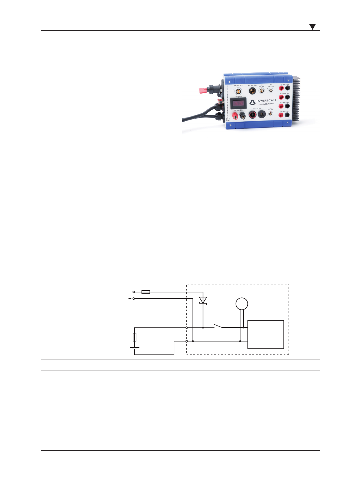
In addition to this one high current connector for a backup battery is installed. As backup battery a standard lead
accumulator with the same voltage level as the board supply should be used. The positive supply input of this backup
battery is connected with a diode to the positive supply of the vehicle board supply. This guaranties that all electrical
loads connected to the DEWE-POWERBOX-11 are supplied through the backup battery, if the vehicle board supply
breaks down for example during start of the engine. The current will not flow from the backup battery to board supply
because of an installed diode. Due to the voltage drop at the diode of approximately 0.3 V at 30 A load, the supply
voltage level of all electrical loads connected to the DEWE-POWERBOX-11 is 0.3 V lower than the input voltage level.
Some applications need the full voltage. In this case connect the vehicle board supply to X0 instead of the backup
battery to bypass the diode and get the full output voltage. Please don't forget to isolate the ends of the main supply
line in this configuration.
Terminal
board
Main switch
Backup battery
Fuse 2
Fuse 1
V
ehicle board supply
X0
D1
S1
DEWE-POWERBOX-11
VU1
Note: Backup batterie voltage level has to be the same as the vehicle board supply!

4
MAIN SYSTEM
Fuses
Please note that Fuse 1 and Fuse 2 are installed to protect the main power and the backup battery cable. The 50
ampere fuse will not protect the cable from the DEWE-POWERBOX-11 to the external electrical loads connected
regarding overload. We recommend to use cables with cross-section area higher than 1.5 mm², which are also
protected against short cut – the fuse will blow before the cable or the connector will be destroyed.
The outputs of the DEWE-POWERBOX-11 are protected by resettable fuses which are easy accessible at the rear panel
of the box. The picture below will show the different fuses used to protect the outputs:
Fuse Output connector Max. load
F1 X8, X11, X12 15 A
F2 X7, X9, X10 15 A
F3 X5 25 A
F4 X3 15 A
F5 X1 30 A
Note: Replace the fuses only with fuses of the same voltage, current rating and type!
Fuse F1..F5 are not user replaceable.
GND-Supply
The DEWE-POWERBOX-11 is shipped with a 5 m cable for the main supply. Although the high cross-section area of
10 mm² the voltage dropout at 30 A load will be around 0.3 V. This is usual not a problem at the positive supply line.
Since this voltage drop is also at the negative supply line ground loops may occur depending on the ground concept
of the connected load. To avoid this, it is recommended to split the main supply cable. The cable for the minus input
should be shorten and connected to a suitable screw direct at the vehicle chassis.
One additional solution is to connect the minus input of the backup battery directly to the vehicle chassis for getting a
very low ohm ground connection.
This is not needed if the POWERBOX is connected to DEWE-2010, DEWE-3020, DEWE-4010 or DEWE-5000 because of
the galvanic isolation of the supply voltage.
F5 F4
F3 F2
F1

5DEWE-POWERBOX-11 • Technical Reference Manual • Prinng version 1.0.0 • July 13, 2016
MAIN SYSTEM
Connectors
The following table gives you an overview of the used connectors and maximum current. Also the absolute limits of
other used components are described.
Device no. Max. current Producer and type number
X0: 50 A Mul -Contact, ID-S6ARNS, ID-B6ARNS
X1: 35 A Lemo, EGG.3B.302
X2: 50 A Hirschmann, PKNI10B
X3: 15 A Pro-Car, 57607000
X4: 50 A Mul -Contact, ID-S6ARNS, ID-B6ARNS
X5: 25 A Lemo, EGG.2B.302
X7, X8: 15 A Lemo, EGG.1B.302
X9 to X12: 15 A Mul -Contact, SLB-4F
Fuse 1: 50 A Pudenz, BF1-50A
Fuse 2: 50 A Pudenz, BF1-50A
D1: 120 A / 40 V Interna onal Rec fi er, 120CNQ045
S1: 100 A RS, 0-605-00
U1: -Datel, DMS-20PC-1-DCM
2-pin female LEMO
EGG.3B.302 (X1)
2-pin female LEMO
EGG.2B.302
(X5)
2-pin female LEMO
EGG.1B.302
(X7, X8)
2-pin Pro-Car power
supply
(X3)
Backup battery X0 X2 X4 X8 X9 to X12
Main power switch S1 X1 U1 X3 X5 X7
Vehicle board supply

6
MAIN SYSTEM
Notes
Table of contents
Popular Power Supply manuals by other brands

Conductix-Wampfler
Conductix-Wampfler 91008-111-3130923 operating instructions

ZALMAN
ZALMAN ZM1000-HP user manual

BCP
BCP PUOOUCBK How to install

Honeywell
Honeywell Fire-Lite FL-PS6 instruction manual

Schrack Technik
Schrack Technik AVARA Multi Power Series user manual

Monacor
Monacor PSS-5000 quick start guide