Dexter Laundry SWAY CONTROL Manual

www.dexteraxle.com
2900 Industrial Parkway East nElkhart, IN 46516
Phone: 574-295-7888 nFax: 574-295-8666
www.dexteraxle.com
ISO 9001 Certied
OPERATION MAINTENANCE SERVICE MANUAL
DEXTER SWAY CONTROL (DSC)
GEARED FOR INNOVATION SINCE 1960
www.dexteraxle.com
4/17 © 2014-2017 Dexter Axle Company. LIT-010-OO

Introduction
Dexter is proud to put control and peace of mind in hauling a trailer or
caravan back into your hands with the Dexter Sway Control System. This
innovative device automatically stabilizes the sway of a trailer. It works
independently of the tow vehicle and automatically applies the trailer or
caravan brakes in the event of a sway.
As you are driving, the Dexter Sway Control System is constantly
monitoring trailer yaw, or side-to-side movement, quickly recognizing and
adjusting for sway conditions.
This manual is designed to provide information for you to understand, use,
and guide you through the process of installing, operating, and maintaining
your Dexter Sway Control System.
Assembled in the USA by Tuson RV Brakes, LLC.
Visit us online at www.dexteraxle.com

-2-
Table of Contents
Dexter Sway Control (DSC) Trailer Mounting ............................3
DSC Mounting Location ......................................................3
Mounting Hardware.............................................................4
DSC Wiring................................................................................7
Trailer Battery......................................................................7
Ground Connections ...........................................................8
12 Volt Connections ............................................................9
Electric Brake (Blue) Wire Connections ............................10
Left and Right Brake Wires ...............................................11
Wire Connections to Trailer Plug and System Overview ...12
DSC Wiring Harness.........................................................13
Functional Test Procedure.......................................................15
Testing the DSC for Correct Wiring ...................................15
The DSC Status Light Module ..........................................18
Status Light and Troubleshooting ............................................19
How the DSC Works................................................................21
Limited Warranty......................................................................22
Video Gallery...........................................................................25
Scan to view
Sway Control video

-3-
Dexter Sway Control Mounting
!
CAUTION
This is the safety alert symbol. It is used to alert you to
potential injury hazards. Obey all safety messages that
follow this symbol to avoid possible injury or death.
CAUTION
The Dexter Sway Control should only be installed by a
qualified technician.
DSC Trailer Mounting
DSC Mounting Location
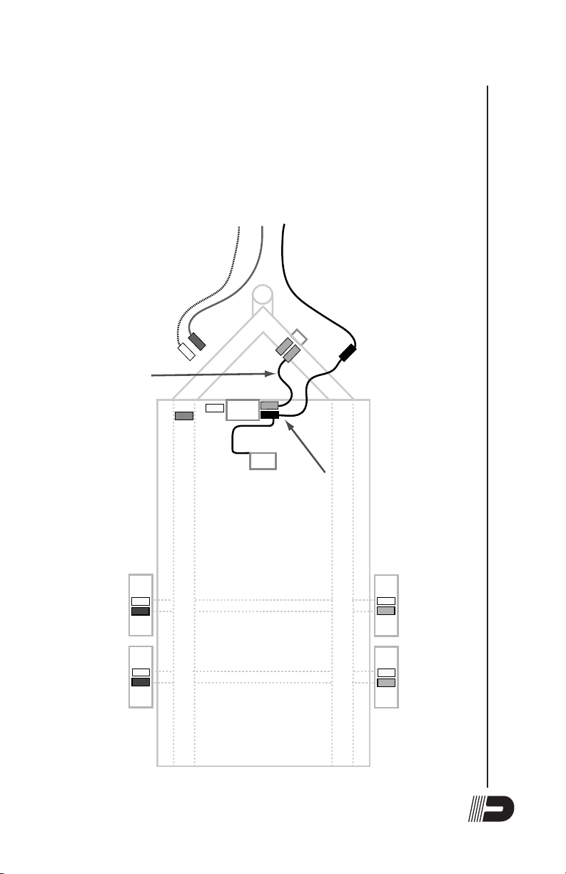
Select a location on the trailer to mount the DSC. The location
must be 5 to 10 feet behind the trailer bumper hitch ball and
shielded from road debris. The DSC must be securely fastened
onto a vertical surface that does not flex or move from wind, such
as plastic covers or plastic walls. The center of the DSC (marked
by a red dot on the DSC label shown below) must be positioned
on the “center line” of the trailer and the DSC must be mounted
with the correct side in the UP direction as indicated on the label.
The longest edge of the DSC (as indicated by a red line on the
label) must be mounted parallel to the trailer axle beam(s). See
Figure 1.
www.dexteraxle.com
Phone: 574-295-7888
Part No. 058-010-00
MOUNT THIS EDGE UP
Mount this edge parallel with the trailer axle beams 5 to 10 feet back
from trailer bumper hitch ball on a vertical frame surface
Module will not function if
positioned and/or oriented
improperly. Read and
follow all Installation Instructions
to ensure proper operation.
WARNING
Wires Trailer Wire Function
Purple Left side electric brakes output
Pink Right side electric brakes output
White Trailer battery/frame ground point
Blue Electric brake controller signal from tow vehicle
Black 12VDC from tow vehicle trailer harness
MOUNT THIS POINT ON TRAILER CENTER LINE
MODULE WIRING
CONNECTOR
ON THIS SIDE
Label No. 059-898-00 Rev C
Assembled in the USA by Tuson RV Brakes, LLC.

-4-
Dexter Sway Control Mounting
It is essential that the DSC be oriented in the proper direction
when it is installed.
CAUTION
Ensure the electric brakes are adjusted and
maintained in accordance with the manufacturer’s
recommendations in your owner’s manual for proper
operation of the sway control module.
Mounting Hardware
The DSC should be mounted using the mounting flanges which
are located on both sides of the unit. Included are four (4) #10
self-tapping screws to mount the DSC to the trailer.
You must NOT drill holes in the DSC for any reason. Drilling holes
or puncturing the unit VOIDS YOUR WARRANTY.
CAUTION
Do not spray high pressure water on the DSC.The DSC
is a weather sealed water resistant unit, but it is not
designed to withstand direct high pressure spray from a
power washer.

-5-
Full Size +12V
Trailer Battery
Break-Away
Switch
-+
Frame
Ground
Left Front
Electric Brake
Left Rear
Electric Brake
Right Rear
Electric Brake
Right Front
Electric Brake
5 to 10 feet
behind hitch
ball
Trailer
Centerline
DSC mounted
with the correct
side in the
UP direction
DSC Center on
Vertical Frame
Surface on Trailer
Centerline
Edge Parallel
with Axle Beams
Dexter
Sway
Control
Front
Rear
Purple
Blue
White
Black
White
Pink
White
Pink
Figure 1
It is essential that the DSC be oriented in the proper direction
when it is installed.
Dexter Sway Control Mounting

-6-
Dimensional Information for
Locating and Mounting
5.75” long
3.5” wide
2.25” high
4.50”
3.625”
2.625”
Figure 2
Dexter Sway Control Mounting

-7-
DSC Wiring
Trailer Battery
The trailer must be equipped with a full size 12 volt battery. Small,
gel-cell type batteries must not be used with the DSC.
Full Size +12V
Trailer Battery
Break-Away
Switch
-
+
Frame
Ground
Left Front
Electric Brake
Left Rear
Electric Brake
Right Rear
Electric Brake
Right Front
Electric Brake
Must Use
Full Size
Trailer Battery
Dexter
Sway Control
Front
Rear
White
Blue
Blue
Blue
Black
+ Battery
White
Purple
White
Pink
White
Pink
Figure 3
Dexter Sway Control Wiring

-8-
Ground Connections
The tow vehicle ground, trailer battery ground, trailer frame
ground, DSC ground (white) wire and the electric brake ground
wires on both sides of the trailer, must all be securely connected
together with 14 gauge wire (min.) in order for the DSC to function
properly.
Full Size +12V
Trailer Battery
Break-Away
Switch
-
+
Frame
Ground
Left Front
Electric Brake
Left Rear
Electric Brake Right Rear
Electric Brake
Right Front
Electric Brake
All Grounds
Connected
Together
Dexter
Sway Control
Rear
Front
White
Blue
Black
White
White
White
Figure 4
Dexter Sway Control Wiring

-9-
12 Volt Connections
The tow vehicle 12 volt charge line, the 12 volt trailer battery
terminal and the DSC 12 volt (black) wire must be securely
connected together with 14 gauge wire (min.) in order for the DSC
to function properly. The “hot” wire from the breakaway switch must
be connected to the +12V terminal of the trailer battery.
Full Size +12V
Trailer Battery
Break-Away
Switch
-
+
Frame
Ground
Left Front
Electric Brake
Purple
Left Rear
Electric Brake
Purple
Right Rear
Electric Brake
Pink
Right Front
Electric Brake
Pink
+ 12 Volt
Connections
Dexter
Sway Control
Break-Away
Switch
“Hot” Wire
+ Battery
Front
Rear
Black
Figure 5
Dexter Sway Control Wiring

-10-
Electric Brake (Blue Wire) Connections
The tow vehicle brake controller signal (blue) wire must be
securely connected to the DSC brake signal (blue) wire as well
as to the “cold” wire from the breakaway switch as shown in the
wiring diagram.
Full Size +12V
Trailer Battery
Break-Away
Switch
-+
Frame
Ground
Left Front
Electric Brake
Purple
Left Rear
Electric Brake
Purple
Right Rear
Electric Brake
Pink
Right Front
Electric Brake
Pink
Blue
Brake
Signal
Wire
Dexter
Sway Control
Break-Away
Switch
“Cold” Wire
Front
Rear
Blue
Blue
Figure 6
Dexter Sway Control Wiring

-11-
Left and Right Side Brake Wires
The DSC operates the left and right side trailer brakes
independently in order to control trailer sway and therefore it is
very important that the correct DSC wires are connected to the
correct side brakes. The DSC purple wire must be connected to
the left side electric brakes with a 14 gauge (min.) wire. The DSC
pink wire must be connected to the right side electric brakes with
a 14 gauge (min.) wire. Failure to properly connect these wires will
prevent the DSC from controlling trailer sway.
Full Size +12V
Trailer Battery
Break-Away
Switch
-
+
Frame
Ground
Left Front
Electric Brake
Left Rear
Electric Brake Right Rear
Electric Brake
Right Front
Electric Brake
Purple Wire
Left Side Brakes
Dexter
Sway Control
Pink Wire
Right Side Brakes
Rear
Front
Figure 7
Dexter Sway Control Wiring

-12-
Wire Connections to Trailer Plug
and System Overview
YELLOW
Back-up
12 gauge
BLUE
Trlr. Brake Sig.
12 gauge
BROWN
Right Turn - Stop
12 gauge
WHITE
Ground
10 gauge
RED
Left Turn - Stop
12 gauge
BLACK
+12 Volts
10 gauge
GREEN
Running Lights
12 gauge
Full Size +12V
Trailer Battery
Break-Away
Switch
-+
Frame
Ground
Running
Lights
Running
Lights
Running
Lights Running
Lights
Running
Lights
Running
Lights
Running
Lights
Left Turn -
Stop Light
Right Turn -
Stop Light
Left Front
Electric Brake
Left Rear
Electric Brake Right Rear
Electric Brake
Right Front
Electric Brake
Wiring Diagram
Bumper Pull Trailer
Electric Drum Brakes
with Dexter Sway Control
Full Size +12V
Trailer Battery
= FRAME GROUND
(wires not shown)
= BREAKAWAY SWITCH
= TRAILER LIGHTS
(wires not shown)
= BACK-UP LIGHTS
(not used)
Dexter
Sway Control
The DSC mounts on
the center line of the trailer, 5 to 10 feet
back from the trailer hitch ball on a
VERTICAL frame surface.
Trailer
Connector
Red
White
Yellow
Blue
Brown
Black
Green
White
Blue
Black
Blue
Green Green
+ Battery
White
Purple
Green Green
White
Pink
White
Pink
Pink
Purple Pink
Purple Pink
Green Green
Red Green Brown
Figure 8
Dexter Sway Control Wiring

-13-
DSC Wiring Harness
The DSC wire harness has five wires requiring electrical
connection and one wire for the status LED light. The function of
each of these wires is outlined in the table below:
DSC
Wires Trailer Wire Function
Wire Gauge
Required
Purple Wire Left side electric brake
output (all left side
brakes)
14 Gage Minimum
Pink Wire Right side electric brake
output (all right side
brakes)
14 Gage Minimum
White Wire Trailer battery/frame
ground point
14 Gage Minimum
Blue Wire Electric brake controller
signal from tow vehicle
14 Gage Minimum
Black Wire 12VDC from tow vehicle
trailer harness
14 Gage Minimum
Gray Wire 10' wire with a two pin
connector on the end that
plugs into the LED status
light
Included in kit
The 14 gauge wires of the DSC wiring harness are approximately
12" long to allow for flexibility when mounting the unit. Extensions
will be required to connect unit to the trailer’s electrical wiring.
When making connections to the trailer’s wiring harness, the
desired termination is a solder joint. If the connection is not
soldered, use the appropriate size and type of “crimp-type”
weather sealed heat-shrink connectors, using the manufacturer’s
recommended crimping tools in accordance with their crimping
instructions.
Once the 14 gauge wires are connected, route the Status Light
wire to a location on the front of the trailer and mount the Status
Light Module onto a flat surface using two (2) #6 self-tapping
screws. Select a location that makes it easy to see the Status
Light when looking at the front of the trailer.
Dexter Sway Control Wiring

-14-
Taking shortcuts when connecting any wires on your trailer only
increases the likelihood that some part of your electrical system
will fail. Make sure your splice connections are durable and sealed
against exposure to water and corrosive elements. One loose wire
connection can disable your entire trailer brake system.
When adding extension wires to the DSC wiring harness, you
must use the correct gauge wire. These gauge sizes are outlined
in the table above.
!
CAUTION
Failure to use the correct gauge wire may result in
poor braking performance or brake failure. Improper
wire gauge may also result in significant damage to
your trailer or its components, cause a fire, which
may result in serious or fatal injury and/or property
damage. Undersized wire will prevent electrical circuit
protection devices such as fuses or circuit breakers
from functioning properly. Undersized wire may melt or
burn before these safety devices can be activated.
Dexter Sway Control Wiring

-15-
Functional Test Procedure
Testing the DSC for Correct Wiring
CAUTION
Before proceeding with the following test procedure,
it is important to have the DSC unit powered on with
a green status light. Failure to power the DSC before
proceeding may result in a permanent failure or
malfunction of the unit.
In order to verify that the DSC is wired correctly, follow the test
process listed below:
1. Ensure that the trailer battery is fully charged or that a
charging device is connected to the trailer.
2. Connect the +12V to the black wire on the DSC and ground
the white wire from the DSC.
3. Connect a brake controller to the brake signal (blue) wire of
the trailer harness.
4. Turn on the brake controller and apply the manual override
until the DSC status light comes on.
5. Verify that the light is GREEN and that it is “flickering”. This
indicates no faults with the DSC. If the light is not GREEN,
refer to the troubleshooting section to correct the detected
fault(s).
6 Refer to Figure 1 and Figure 2 on the following page to
verify correct wiring on the left and right sides of the trailer.
After the trailer passes the left side test, reconnect the left
side brake as normal before repeating for the right side test.
Note: It is very important for the wire test connection to
be made back near the left and right side trailer brakes.
Do not perform this test up front near the DSC since
that will not verify correct wiring back at the brakes.
7. If the DSC status light does not flash the correct number of
times as indicated in Figures 1 and 2, make the necessary
wiring changes so that the flashes match the correct side.
Functional Test Procedure

-16-
Functional Test Procedure
8. After the trailer passes the test as shown in Figures 1 and
2 and the brakes are reconnected as normal, verify that the
GREEN flickering light is displayed. If it is not, refer to the
troubleshooting section to correct the detected fault(s).

-17-
3 RED
Flashes
DSC
Status
Light
Module
Status
Light
Cable
Temporarily
connect the
Purple and
White wire
at ONE brake
location and
verify the
status LED
flashes RED
3 times
LEFT Side
Brake Wires
PURPLE - Brake
Control
WHITE - Ground
Purple
4 RED
Flashes
DSC
Status
Light
Module
Status
Light
Cable
Temporarily
connect the
Pink and
White wire
at ONE brake
location and
verify the
status LED
flashes RED
4 times
RIGHT Side
Brake Wires
PINK - Brake
Control
WHITE - Ground
Pink
Figure 1 Figure 2
Functional Test Procedure

-18-
The DSC Status Light Module
The DSC performs a self-diagnostic test every time it “wakes up”
by receiving a signal from a brake controller in the tow vehicle.
The light will flash RED and GREEN approximately six times on
startup and then go to GREEN. The DSC also continually monitors
system parameters during operation. If the system is operating
properly and no faults are detected, the GREEN light will remain
ON and flicker or pulse. If a problem is detected, a RED light will
flash a specific number of times to indicate the specific problem.
The following Status Light and Troubleshooting table contains the
meaning of the different RED and GREEN light flashes along with
troubleshooting suggestions to correct the problem(s).
The DSC continues checking the fault status and keeps the RED
light flashing until the fault is corrected. Once corrected, the
GREEN light returns. Note that when the trailer is not moving,
every 60 seconds the GREEN light will turn off for three seconds
and back on. This is normal and indicates proper operation of
the DSC. If the GREEN light is not turning off and on every 60
seconds while the trailer is not moving, have the DSC checked by
your local service center.
Functional Test Procedure

-19-
Status Light and Troubleshooting
Mount the Status Light Module in a location on the front of the
trailer where the light is easily seen.
Light Action Condition Corrective Action
Solid GREEN
pulsing
Normal operation –
no system faults
No action – system ok
.
1 GREEN flash Module reset to
manufacturers
default values. Keep
trailer sitting still
for minimum 30
seconds, then drive
normally.
If module does not
return to normal solid
GREEN pulsing light
after three system
restarts, have the unit
checked at a service
center.
RED, GREEN.
RED, GREEN,
continuing...
Rough terrain
mode.
No action – system
will momentarily
return to normal
function.
No light Unit in “sleep”
mode.
Activate manual
override on the brake
controller to “wake up”
unit.
No light No power after
“wake up” from
brake controller.
Verify the unit has
good quality power,
ground and brake
controller wire
connections. Check
for any blown fuses
on the truck and
trailer.
No light Over voltage – over
+20 volts.
Check that power
source is not
exceeding 20 volts.
Correct voltage to
12-15 volts.
Status Light and Troubleshooting
This manual suits for next models
1
Table of contents
Popular Automobile Accessories manuals by other brands

Peruzzo
Peruzzo SMART RACK DELUX Fitting instructions

Warn
Warn Ford Performance M-1821-SD Installation instruction

Whispbar
Whispbar WBT21 user manual

Pyle
Pyle PLCM4565 user manual

Continental Refrigerator
Continental Refrigerator ContiComfortKit operating instructions

Curt Manufacturing
Curt Manufacturing 4516 installation instructions

Truck Hero
Truck Hero TruXedo Sentry CT owner's manual

Metra Electronics
Metra Electronics 99-7300 installation instructions

Whispbar
Whispbar K847W Fitting instructions

AA Products
AA Products KSX105 instruction manual

Acewell
Acewell MA-085-3 Series user manual

Kargo Master
Kargo Master 4A873 Instruction guide