DFE TRUETENSION TA1 User manual

(603) 322-6150 5 Year Warranty www.dfe.com
THE TENSION CONTROL SPECIALISTS
MODEL TA1
TRUETENSION™ AMPLIFIER
QUICK START GUIDE
SAFETY
This label indicates: “Read the Manual”
Make sure you read and understand all instructions and safety precautions listed in
this manual before installing or operating your TA1 True Tension™ Amplifier. If you have
any questions concerning the operation of your device or the information in this
manual, please contact us.
Email: techsupport@dfe.com
Telephone: (603) 332-6150
• Observe all warning labels.
• Never remove warning labels.
WARNING: If this equipment is not connected or operated in the manner
specified, the operating safety of this unit or of connected equipment cannot be
guaranteed.
WARNING: The isolated output is designed to prevent ground loops and noise.
It is not intended or approved for safety isolation of hazardous voltages. Do not
install unit where isolated circuit and chassis ground are more than 40 Vpk
dierential.

The TA1 has no mechanical knobs, or switches to operate. All that is needed is a screw-
driver to connect the wires and a pen to press the Zero and Cal buttons. Labels on each
side of the product list:
1. Electrical connections and Cal / Zero blink sequences.
2. All safety/certification icons, input / output information and serial number.
Mount the unit either on a standard DIN rail or snap out the screw holders to mount
with hardware.
In addition to this Quick Start guide, please review the TA1 Instruction Manual (DFE
P/N 801-2568) online at www.dfe.com to familiarize yourself with all of the unit’s spec-
ifications, calibration and zeroing procedures, safety information, and wiring diagrams.
1
INITIAL UNBOXING AND MOUNTING
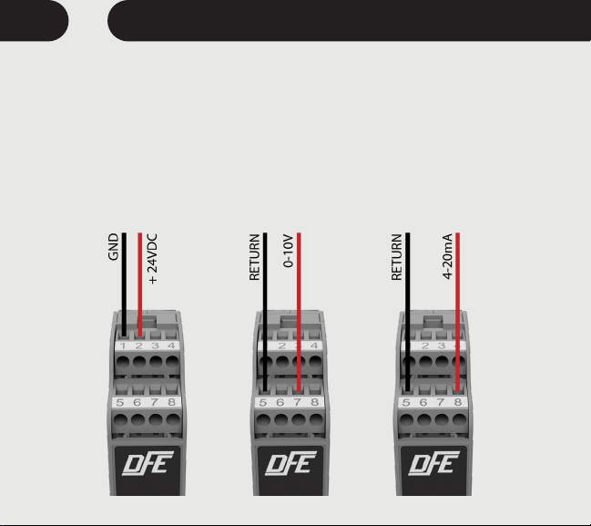
1. Power Input
Power should be
sourced to the TA1 on
Pins 1 (GND) and
2 (+24 VDC)
2. Tension Input
The tension output signal
is provided in two options:
• 0-10 V is available on
Pins 5 (Return) & 7 (0-10 V)
• 4-20 mA is available on
Pins 5 (Return) and 8 (4-20 mA)
POWER AND OUTPUT CONNECTIONS
Power Input Tension Output 0-10 V Tension Output 4-20 mA
2

Make your connections based on the type of transducer you have.
TRANSDUCER ELECTRICAL CONNECTIONS
MODEL C / F / UPB / RS MODEL TR / NW / RFA / VNW / LT
3
A calibration process must be performed before your amplifier is ready to indicate
tension. Select an appropriate calibration weight. The weight determines the value of
web tension that will produce full output of the TA1. For example: A 15 lb weight will
result in full output at 150 lbs of tension if the 10% calibration is performed. If a calibra-
tion of 25% is used, a calibration weight of 15 lbs will result in a full output at 60 lbs of
tension. The first step of any calibration is Zeroing out the amplifier.
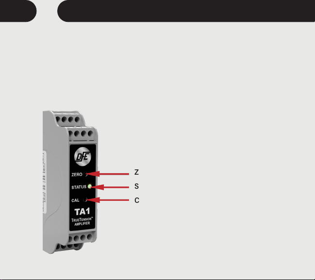
Zero Button - Used to zero the amplifier
Status LED - Indicator light for amplifier status
Cal Button - Used to calibrate the amplifier
4CALIBRATION AND ZERO

1. ZERO: Ensure nothing is hanging on or pressing on the transducer roll (including the
calibration rope). Press the ZERO pushbutton on the unit front panel for at least 1
second. The unit will automatically adjust and store the tension-zero value one second
after the button is pressed. The unit will rapid flash the green status LED to indicate
the zero has been stored. Release the button. The Output1 will read 0 VDC and Output2
will read 4 mA.
2. CALIBRATION: During the calibration the transducer(s) should be loaded. Fasten
one end of the rope in the machine and thread the other end around the transducer
roll in exactly the same path the web will take. Be sure the rope does not pass
around any driven rolls, drag bars, or anything else that can aect tension. Ideally
the rope should hit an idler roll immediately before and after the tension sensing roll.
It does not have to pass over any other rollers once these three are strung. Attach
the weight to the free end of the rope as shown in Figure 10. The weight should not
touch anything. Wait for the weight to stop swinging.
To calibrate at 10% :
Push and Hold the Cal Button (About 1 Second) until confirmation blinks, then release
the button. The output will read 10% of full scale after calibration.
To calibrate at 25% :
Push and Hold Cal Button (About 10 Seconds) until you see two sets of confirmation
blinks. Then release the button. The output will read 25% of full scale after calibration.
If no blink, inadequate Cal weight used.
5
CALIBRATION AND ZERO continued...

Remove the weight and observe the output. It should read 0 VDC or 4 mA with nothing
touching the tension sensing roller. Calibration weight percentage is 25% of full scale.
The TA1 is running normally when the status LED is showing a solid green. If it is not
staying on and is blinking, refer to the list of blink sequences indicating errors.
Perform the action required to clear them. Contact Technical Support if you need
additional help.
Your TA1 is now calibrated and ready for operation.
6CALIBRATION AND ZERO continued...

Normal Operation = Solid Green
1 BLINK = No Calibration Performed
Action Required: Perform Calibration. TA1 is not factory calibrated. A calibration
must be performed at the customers site. Each calibration is specific to the
installation configuration. If using CAL B – a separate calibration must be performed.
2 BLINKS = Outside Cal Range
Once calibrated the TA1 will indicate an over range or under range condition by
setting the error code to ‘Outside Cal Range’. The error is active once -20% or 120%
tension is exceeded.
Action Required: To clear this error the tension must be brought back into rang, or
a new calibration will need to be performed to do so.
3 BLINKS = Wiring Error
Will alert until the load cell are wired correctly.
Action Required: Check wiring and retry. Refer to page 4. Check for loose wires at
the terminal blocks, check for shorts, and be sure the load cells are connected. If the
transducers need trouble shooting – contact tech support for assistance.
Overload Condition (LT Transducer):
Will intermittenly alert if overload is reached.
Action Required: Check that the tension range does not exceed the transducer
load rating. Reduce wrap angle to reduce eective net force exerted on load cell.
7
TROUBLESHOOTING
4 BLINKS = Excitation Failure or Wiring Error
Action Required: Check for shorts in the transducer / load cell wiring. If the
transducers need trouble shooting – contact tech support for assistance.
5 BLINKS = DAC/ADC Internal Failure
Action Required: Contact DFE for replacement.
8TROUBLESHOOTING

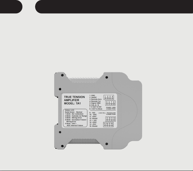
9
DIMENSIONS
To view or download the TA1 Instruction Manual go to:
https://dfe.com/products/ta1-tension-amplifier.html
Please call Technical Support if you need assistance.
E-mail: techsupport@dfe.com
Engineered • Supported • Made in the USA
©2021 Dover Flexo Electronics, Inc.
All Rights Reserved
0317 Doc 801-2571 R1
MADE IN USA
5 YEAR WARRANTY
DOVER FLEXO
ELECTRONICS
Ph: 603-332-6150 • www.dfe.com
www.dfe.com info@dfe.com
TA1
TA1
TA1
True Tension Amplifier
Model #
Product Name:
RoHS
COMPLIANT
TA1C02100001
www.dfe.com
307 Pickering Rd, Rochester, NH 03867 USA
Phone: (603) 332-6150 • FAX: (603) 332-3758 • Email: info@dfe.com • Website: www.dfe.com
THE TENSION CONTROL SPECIALISTS
DOVER FLEXO ELECTRONICS, INC.
Other manuals for TRUETENSION TA1
1
Table of contents
Other DFE Amplifier manuals


