DFE TRUETENSION TA1 User manual

INSTRUCTION MANUAL
TRUETENSIONTM Model TA1
Tension Amplifier
DOC 801-2568 R2

Dover Flexo Electronics
307 Pickering Road
Rochester, NH 03867- 4630
U.S.A.
FOR ASSISTANCE:
TECHNICAL SERVICE - Installations, Start-Up, Troubleshooting, Repairs, Field
Service, Returns: mailto: techsupport@dfe.com call
(603) 332-6150 and ask for Technical Support or email to
CUSTOMER SERVICE - Replacement Parts, Individual Products, Questions about
Orders, Manuals: mailto: customerservice@dfe.com call
(603) 332-6150 and ask for Customer Service or email to
us at customerservice@dfe.com
SALES - Product Information, Systems Application Questions, and
placing orders for standard products and special systems.
Please mailto: sales@dfe.com call (603) 332-6150 and ask
for Sales or email to us at sales@dfe.com
Telephone: (603) 332-6150 Fax: (603) 332-3758
©2020 Dover Flexo Electronics, Inc. All rights reserved. Dover Flexo Electronics has made reasonable effort to ensure accuracy of this
document. However NO WARRANTY, whether expressed or implied, is given regarding the completeness or correctness of information
in this document. Dover Flexo Electronics shall not be liable for damages of any kind arising from the use or misuse of this document.
Dover Flexo Electronics reserves the right to make changes, additions, and deletions to this document without notice and without
obligation.

This label indicates: “Read the manual”
Make sure you read and understand all instructions and safety precautions listed in this manual
before installing or operating your TA1 True Tension Amplifier. If you have any questions
concerning the operation of your device or the information in this manual, please contact us.
Telephone: (603) 332-6150
• Observe all warning labels.
•Never remove warning labels.
!WARNING: If this equipment is not connected or operated in the manner specified, the
operating safety of this unit or of connected equipment cannot be guaranteed.
!WARNING: The isolated output is designed to prevent ground loops and noise. It is not
intended or approved for safety isolation of hazardous voltages. Do not install unit where the
isolated circuit and chassis ground are more than 40 Vpk differential.

Table of Contents
1.0 Overview / Device Description
1.1 General Description ...................................... 1
1.2 Specifications................................................ 1
1.3 Features ........................................................ 1
2.0 Installation
2.1 Dimensions .................................................. 2
2.2 Mounting the Unit ......................................... 2
2.3 Standard Electrical Connections .................. 3
2.4 Optional Electrical Connections ................... 5
3.0 Operation
3.1 Hardware Identification ................................ 6
3.2 Calibration .................................................... 6
4.0 Operation
4.1 Troubleshooting ........................................... 8
APPENDIX A:
Transducer Connections .......................................... 9
Terms and Conditions ...................................... 11
Figures:
1 Dimensions ................................................... 2
2 Removing From DIN Rail .............................. 2
3 Convert to Screw Mount .............................. 3
4 Power Input Connections.............................. 3
5 Tension Output Electrical Connections ........ 3
6 Transducer Electrical Connections............... 4
7 Cal A/B Electical Connections ..................... 5
8 Remote Cal and Zero Connections ............. 5
9 Locations of Zero/Cal Buttons and
Status LED ................................................... 6
10 Web Path ...................................................... 7
11 Electrical Connections for Transducer
Models C, and F............................................ 9
12 Electrical Connections for Transducer
Models NW, RFA, TR, LT and VNW ............ 10

1OVERVIEW / DEVICE DESCRIPTION
1.1 General Description
The TA1 TrueTension™Amplifier with Quik-Cal™push-button zero and calibration is a
compact, versatile single-channel tension transducer interface. It can be used with DFE
tension transducers to monitor tension in any zone on web or filament processing
machinery.
The TA1 amplifier is powered by 24 VDC and supplies an excitation signal to connected
tension transducers installed in a machine's web path. The amplifier boosts the millivolt-
level tension-signal input from a DFE tension transducer (or transducer pair) to output a
proportional 0-10 VDC (isolated) and 4-20 mA signal to a PLC, drive or display meter.
The standard configuration for the TA1 is a 3.9"H x 4.41"D x 0.89"W enclosure with
connector terminals that mounts in a vertical orientation onto a DIN rail. The unit can
also be screw mounted. The TA1 is CE marked.
1.2 Specifications
Power Input: Voltage: 24 VDC +/- 10%, Current: 0.1 ADC typical, internal fusing PTC
resettable
Temperature Range: 32EF to 122EF (0EC to 50EC)
Tension Amplifier Accuracy: +/- 1/2% drift at ambient maximum
Tension Outputs: Output 1: 0-10 VDC isolated from 24 VDC input GND
Output 2: 4-20 mA isolated from 24 VDC input GND
Calibration Range: Up to 50:1
Processor: 32 Bit
Weight: 0.25 lbs (114g)
Resolutions: ADC - 16,777,216(24 Bit), DAC - 4,096 (12 Bit)
1.3 Features
•Quik-Cal™ push-button zero and calibration eliminates pot adjustments to make
calibrating simple and fast.
•10% or 25% Calibration Ratio. Full output when tension is at 10 or 4 times the
calibration weight.
•DIN Rail Clip. To be used with 35 mm DIN rail. Can be converted to screw mount.
•2 Tension Outputs. Outputs a 0-10 VDC and 4-20 mA proportionate signal to a
PLC, drive, or display meter.
•Dual Calibration. Allows two calibration settings. Dual calibration example
applications:
a. One set of transducers operating in a wide tension range. Dual calibration and
dual meter scale is used to enhance the resolution of indicated tension.
b. One set of transducers that may be subject to two different wrap angles or web
paths. In this case a dual meter scale may, or may not, be required.
•Status LED. Green LED flashes to verify ZERO and CALIBRATION, and indicates
presence of power and proper circuit operation. If power is on and no faults are
detected, LED will be on solid. LED will flash momentarily to indicate acceptance of
a ZERO or CALIBRATION button push.
1

FIGURE 1 - Dimensions
2INSTALLATION
2.1. Dimensions
2.2 Mounting the Unit
The unit is DIN rail mountable, compatible with DIN35mm rail. Snap on to mount. To
remove from the DIN rail, use a screwdriver and release the clamp as shown below.
FIGURE 2 - Removing from DIN Rail
2
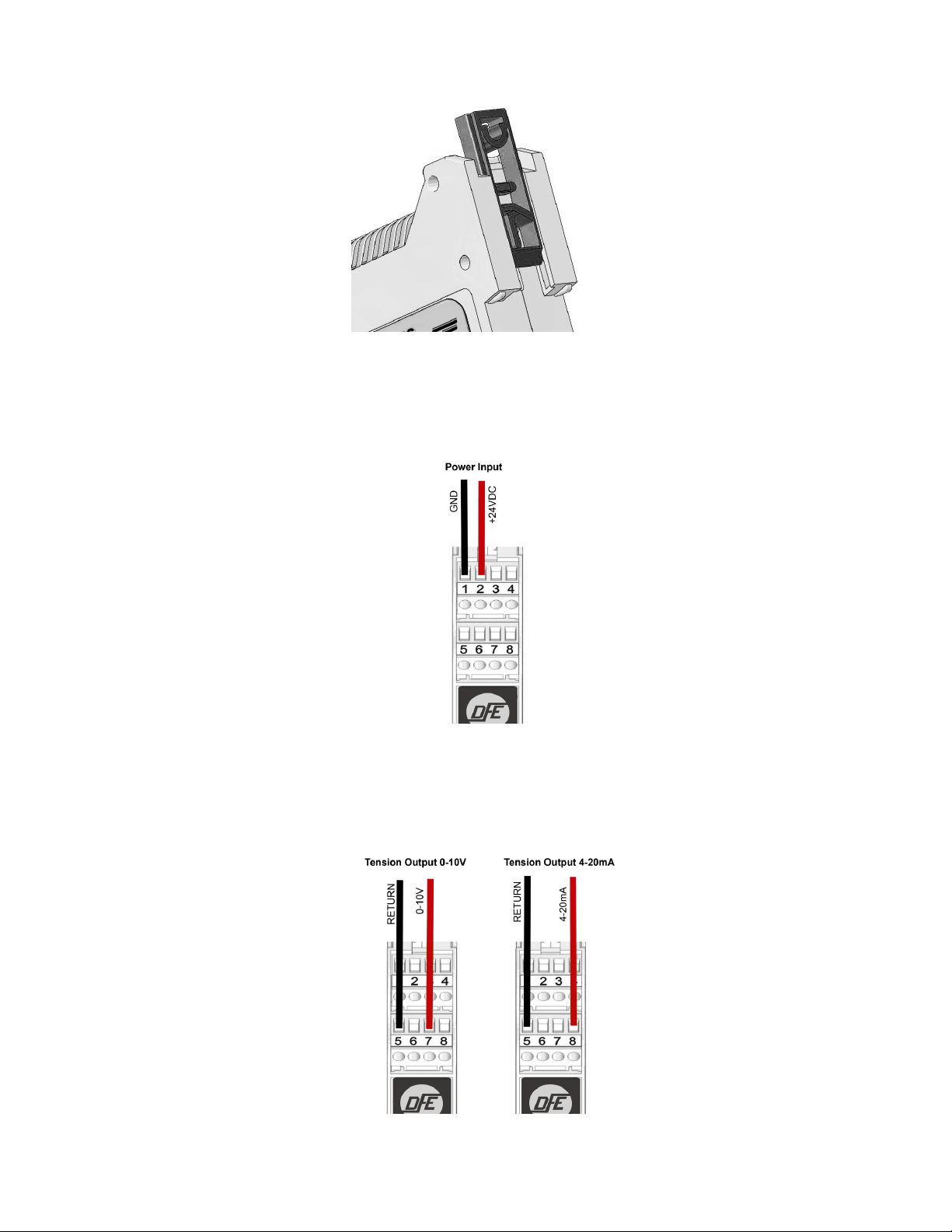
FIGURE 3 - Convert to Screw Mount
2.2 Mounting the Unit continued...
The unit can also be screw mounted. By adjusting the top and bottom clips to the outer
positions.
2.3 Standard Electrical Connections
1. Power Input
Power should be sourced to the TA1 on Pins 1 (GND) and 2 (+24 VDC)
FIGURE 4 - Power Input Connections
2. Tension Output
The tension output signal is provided in two options:
• 0-10 V is available on Pins 5 (Return) and 7 (0-10 V)
• 4-20 mA is available on Pins 5 (Return) and 8 (4-20 mA)
FIGURE 5 - Tension Output Electrical Connections
3

2.3 Standard Electrical Connections continued....
3. Transducers / Load Cells
FIGURE 6 - Transducer Electrical Connections
(See Appendix A for full Electrical Connections)
Below is label on left side of unit:
4

2.4 Optional Electrical Connections
1. CAL A/B (Dual Calibration)
Dual Calibration allows two calibration settings. To operate the TA1 amplifier in the
Calibration A configuration the connection to PIN 6 must be left open.
To operate the TA1 in the Calibration B configuration the 24V must be applied to PIN
6. A switch can be used as shown below. If a PLC or alternate source for 24V is
utilized be sure that the source has a common Ground with PIN 1. If you do not need
dual calibration no connection needs to be made to PIN 6.
FIGURE 7 - Cal A/B Electrical Connections
(See Appendix A for full Electrical Connections)
2. Remote Calibrate and Zero
FIGURE 8 - Remote Calibration and Zero Connections
(See Appendix A for full Electrical Connections)
5
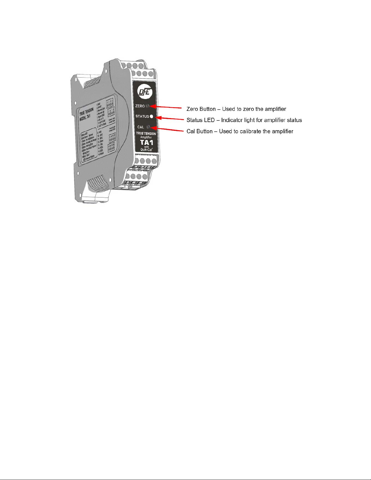
FIGURE 9 - Location of Zero, Cal Buttons and Status LED
3OPERATION
3.1 Hardware Identification
3.2 Calibration
A calibration process must be performed before your amplifier is ready to indicate
tension. Select an appropriate calibration weight. The weight determines the value of
web tension that will produce full output of the TA1. For example: A 15 lb weight will
result in full output at 150 lbs tension if the 10% calibration is performed. If a calibration
of 25% is used, a calibration weight of 15 lbs will result in a full output at 60 lbs tension).
The first step of any calibration is Zeroing out the amplifier.
1. ZERO: Ensure nothing is hanging on or pressing on the transducer roll (including the
calibration rope).
Press the ZERO pushbutton on the unit front panel for at least 1 second. The unit will
automatically adjust and store the tension-zero value one second after the button is
pressed. The unit will rapid flash the green status LED to indicate the zero has been
stored. Release the button. The Output1 will read 0 VDC and Output2 will read 4 mA.
2. CALIBRATION: During the calibration the transducer(s) should be loaded. Fasten
one end of the rope in the machine and thread the other end around the transducer
roll in exactly the same path the web will take. Be sure the rope does not pass
around any driven rolls, drag bars, or anything else that can affect tension. Ideally
the rope should hit an idler roll immediately before and after the tension sensing roll.
It does not have to pass over any other rollers once these three are strung. Attach
the weight to the free end of the rope as shown in Figure 10. The weight should not
touch anything. Wait for the weight to stop swinging.
6
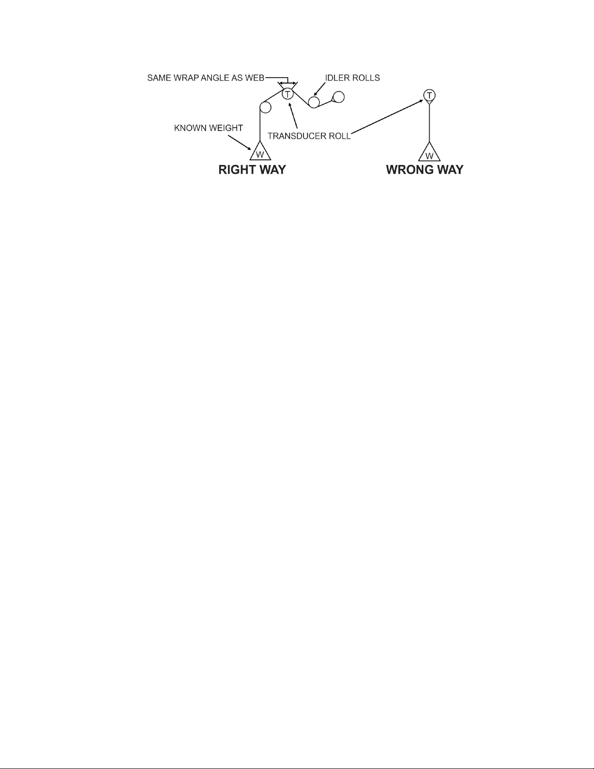
FIGURE 10 - Web Path
3.2 Calibration continued....
To calibrate at 10%:
Push and Hold the Cal Button (About 1 Second) until confirmation blinks, then release
the button. The output will read 10% of full scale after calibration.
To calibrate at 25%:
Push and Hold Cal Button (About 10 Seconds) until you see two sets of confirmation
blinks. Then release the button. The output will read 25% of full scale after calibration. If
no blink, inadequate Cal weight used.
Remove the weight and observe the output. It should read 0 VDC or 4 mA with nothing
touching the tension sensing roller.
Calibration weight percentage is 25% of full scale.
Your TA1 is now calibrated and ready for operation.
7

4TROUBLESHOOTING
4.1 Troubleshooting
The TA1 is running normally when the status LED is showing a solid green. If it is not
staying on and is blinking, refer to the list of blink sequences indicating errors. Perform
the action required to clear them. Contact Technical Support if you need additional
help.
Normal operation: Solid Green
• 1 Blink = No Calibration Performed
Action Required: Perform Calibration.TA1 is not factory calibrated. A calibration
must be performed at the customers site. Each calibration is specific to the
installation configuration. If using CAL B – a separate calibration must be performed.
• 2 Blinks = Outside Cal Range
Once calibrated the TA1 will indicate an over range or under range condition by
setting the error code to ‘Outside Cal Range’. The error is active once -20% or 120%
tension is exceeded.
Action Required: To clear this error the tension must be brought back into range, or
a new calibration will need to be performed to do so.
• 3 Blinks
Wiring Error:
- Will alert until the load cells are wired correctly.
-Action Required: Check wiring and retry. Refer to page 4. Check for loose wires
at the terminal blocks, check for shorts, and be sure the load cells are connected. If
the transducers need trouble shooting – contact tech support for assistance.
Overload Condition (LT Transducer):
-Will intermittenly alert if overload is reached.
-Action Required: Check that the tension range does not exceed the transducer
load rating. Reduce wrap angle to reduce effective net force exerted on load cell.
• 4 Blinks = Excitation Failure or Wiring Error
Action Required: Check for shorts in the transducer / load cell wiring. If the
transducers need trouble shooting – contact tech support for assistance.
• 5 Blinks = DAC/ADC Internal Failure
Action Required: Contact DFE for replacement.
8
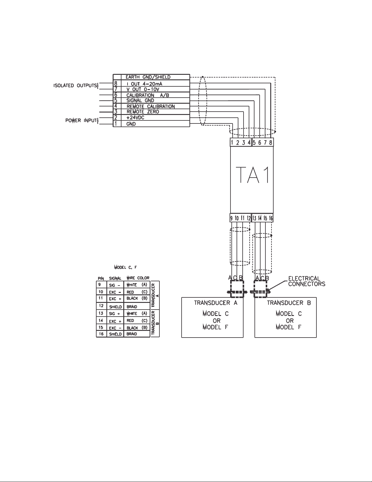
FIGURE 11 - Electrical Connections for Models C & F Transducers
APPENDIX A: Transducer Connections
9
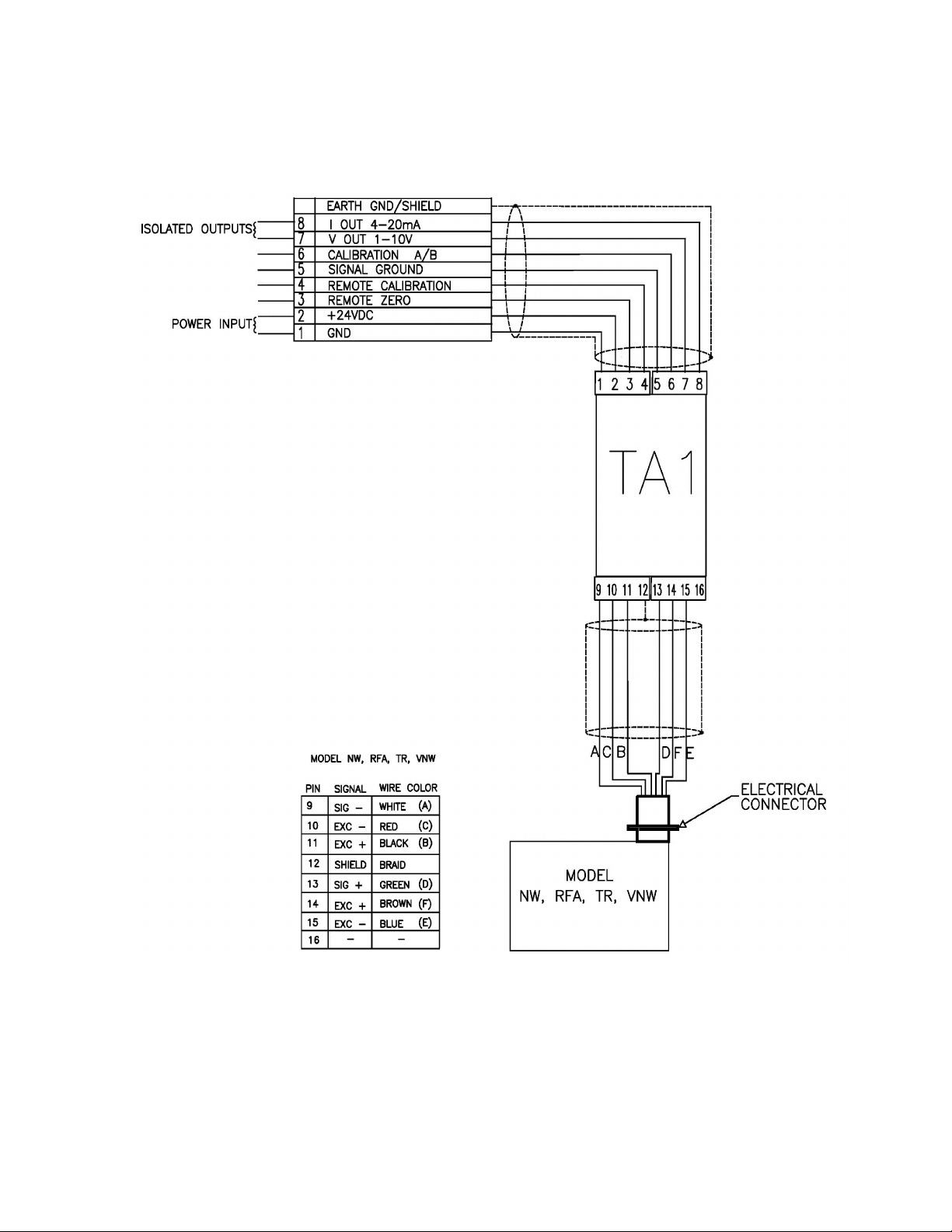
APPENDIX A: Transducer Connections continued...
Figure 12 - Electrical Connections for NW, RFA, TR, LT & VNW Transducers
10

TERMS AND CONDITIONS OF SALE AND SHIPMENT
1. THE COMPANY
Dover Flexo Electronics, Inc. is hereinafter referred to as the Company.
2. CONFLICTING OR MODIFYING TERMS
No modification of, additions to or conflicting provisions to these terms
and conditions of sale and shipment, whether oral or written, incorpo-
rated into Buyer's order or other communications are binding upon the
Company unless specifically agreed to by the Company in writing and
signed by an officer of the Company. Failure of the Company to object
to such additions, conflicts or modifications shall not be construed as a
waiver of these terms and conditions nor an acceptance of any such
provisions.
3. GOVERNING LAW
This contract shall be governed by and construed according to the laws
of the state of New Hampshire, U.S.A. The parties agree that any and
all legal proceedings pursuant to this contract shall take place under the
jurisdiction of the courts of the State of New Hampshire in the judicial
district of Strafford County.
4. PENALTY CLAUSES
Penalty clauses of any kind contained in orders, agreements or any
other type of communication are not binding on the Company unless
agreed to by an officer of the Company in writing.
5. WARRANTY
Dover Flexo Electronics, Inc. warrants, to the original Buyer, its'
products to be free of defects in material and workmanship for five
years from date of original shipment. Repairs on products are
warranted for 90 days from date of shipment. During the warranty
period the Company will repair or replace defective products free of
charge if such products are returned with all shipping charges prepaid
and if, upon examination, the product is shown to be defective. This
warranty shall not apply to products damaged by abuse, neglect, acci-
dent, modification, alteration or mis-use. Normal wear is not
warranteed. All repairs and replacements under the provisions of this
warranty shall be made at Dover Flexo Electronics or at an authorized
repair facility. The Company shall not be liable for expenses incurred to
repair or replace defective products at any other location or by unautho-
rized persons or agents. This warranty contains all of the obligations
and warranties of the Company. There are no other warranties, either
expressed or implied. No warranty is given regarding merchantability or
suitability for any particular purpose. The Company shall not be liable
in either equity or law for consequential damages, losses or expenses
incurred by use of or inability to use its' products or for claims arising
from same. No warranty is given for products of other manufacturers
even though the Company may provide these products with its' own or
by themselves. The provisions of this warranty can not be changed in
any way by any agent or employee of the Company. Notice of defects
must be received within the warranty period or the warranty is void. The
warranty is void if the serial number tag is missing or not readable.
6. PAYMENTS
Standard terms of credit are net 30 days from date of shipment,
providing satisfactory credit is established with the Company. Amounts
past due are subject to a service charge of 1.5% per month or portion
thereof or 18% per annum. The Company reserves the right to submit
any unpaid late invoices to a third party for collection and Buyer shall
pay all reasonable costs of such collection in addition to the invoice
amount. All quoted prices and payments shall be in U.S. Dollars. If the
Company judges that the financial condition or payment practices of the
Buyer does not justify shipment under the standard terms or the terms
originally specified, the Company may require full or partial payment in
advance or upon delivery. The Company reserves the right to make col-
lection on any terms approved in writing by the Company's Finance
Department. Each shipment shall be considered a separate and
independent transaction and payment therefore shall be made accord-
ingly. If the work covered by the purchase order is delayed by the
Buyer, upon demand by Company payments shall be made on the
purchase price based upon percentage of completion.
7. TAXES
Any tax, duty, custom, fee or any other charge of any nature whatso-
ever imposed by any governmental authority on or measured by any
transaction between the Company and the Buyer shall be paid by the
Buyer in addition to the prices quoted or invoiced.
8. RETURNS
Written authorization (MRA) must be obtained from the Company's
factory before returning any material for which the original Buyer
expects credit, exchange, or repairs. Material returned for credit must
be unused, received back within 30 days of original ship date and shall
be subject to a re-stocking charge of 15%. Special Product Requests
(SPRs), product manufactured specially to customer specifications, and
non-DFE product purchased on customer behalf shall not be returnable
for any reason. All material returned, for whatever reason, shall be sent
with all freight charges prepaid by the Buyer.
9. SHIPPING METHOD AND CHARGES
All prices quoted are EXW the Company's factory. The Company shall
select the freight carrier, method and routing. Shipping charges are
prepaid and added to the invoice of Buyers with approved credit,
however the Company reserves the right to ship freight-collect if it
prefers. Shipping charges will include a charge for packaging. Company
will pay standard ground freight charges for items being returned to
Buyer which are repaired or replaced under the Warranty. Claims of
items missing from a shipment must be received, in writing, within 30
days of original shipment
10. CANCELLATION, CHANGES, RESCHEDULING
Special Product Requests (SPRs), product manufactured specially to
customer specifications, and non-DFE product purchased on customer
behalf shall not be returnable for any reason. Buyer will be subject to a
15% fee for any standard item on order with the Company which is
cancelled by the Buyer. A one-time hold on any item ordered from the
Company shall be allowed for a maximum of 30 days. After 30 days, or
upon notice of a second hold, Company shall have the right to cancel
the order and issue the appropriate cancellation charges which shall be
paid by Buyer. Items held for the Buyer shall be at the risk and expense
of the Buyer unless otherwise agreed upon in writing. Company
reserves the right to dispose of cancelled material as it sees fit without
any obligation to Buyer. If Buyer makes, or causes to make, any
change to an order the Company reserves the right to change the price
accordingly.
11. PRICES
Prices published in price lists, catalogs or elsewhere are subject to
change without notice and without obligation. Written quoted prices are
valid for thirty days only.
12. EXPORT SHIPMENTS
Payment for shipments to countries other than the U.S.A. and Canada
or to authorized distributors shall be secured by cash in advance or an
irrevocable credit instrument approved by an officer of the Company. An
additional charge will apply to any letter of credit. There will also be an
extra charge for packaging and documentation.
13. CONDITION OF EQUIPMENT
Buyer shall keep products in good repair and shall be responsible for
same until the full purchase price has been paid.
14. OWNERSHIP
Products sold are to remain the property of the Company until full
payment of the purchase price is made.
Rev.10 10/15/19
11

307 PICKERING ROAD
ROCHESTER, NEW HAMPSHIRE 03867-4630
U.S.A
TEL: (603) 332-6150
FAX: (603) 332-3758
CANADA
MEXICO
UNITED KINGDOM
TAIWAN
KOREA
CHINA
INDIA
AUSTRALIA
SOUTH AFRICA
©2021DOVER FLEXO ELECTRONICS, INC.
ALL RIGHTS RESERVED
0624 DOC 801-2568 R2
PRINTED IN USA
Other manuals for TRUETENSION TA1
1
Table of contents
Other DFE Amplifier manuals


