DFI OPS100-SH User manual

1
OPS100-SH Installation Guide
Package Contents
• One
OPS100-SH System Unit
• One
OPS-DB Docking Board
•
One Quick Installation Guide
•
One DVD disk includes:
- Manual
DFI reserves the right to change the specications at any time prior to
the product's release. For the latest revision and more details of the
installation procedure, please refer to the user's manual on the website.
Notes:
1. Throughout this guide the OPS100-SH may be referred to as the
OPS+ Module
.
2. The OPS-DB (referred to as the Docking Board) is an expansion dock, which
provides additional I/O connectivity.
www.d.com

2
Panel: OPS100-SH
Mic-in
Line-outPower Button
HDD LED
HDMI-in
USB 3.0
COM LAN
Reset Button
microSD Card
Antenna Hole(1)
Antenna Hole(1)
Front View
Notes:
1. The OPS+ Module is equipped with a Wi-Fi module to provide Wi-Fi connectivity.
Please install antennas to these SMA connectors.
2. There may not be indicator light depending on the installed Wi-Fi module; for
example, the LED will not be lit for Intel®Dual Band Wireless-AC 8260.
Panel: OPS-DB
Rear View
HRS FX18 JAE TX25A
DP(B)
Power Button
DP(A)
COM USB 3.0
HDMI-out
USB 2.0
DC-in
Wireless LED(2)

3
Removing the Chassis Cover
1. Make sure the system and all other peripheral devices connected to it
have been powered-off.
2. Disconnect all power cords and cables.
3. The 6 mounting screws on the sides and top cover of the system
chassis, and the 3 screws that afx the front panel to the chassis should
all be removed to open the system. Put these screws in a safe place for
later use.
4. Lift the cover up to open the system.
5. The SODIMM sockets are readily accessible after removing the chassis
cover.
Mounting screw
Mounting screw
Mounting screw
CPU fan SODIMM
The OPS+ Module consists of a computing board in a wrapper chassis.
Pease observe the following guidelines and follow the procedure to open the
system.

4
Installing the OPS100-SH into a Display
2. Secure the module by attaching two screws on the front panel.
Integrating a computing system into a digital signage display is made easy
by standardizing the connectors and signals between an OPS+ Module
and an OPS-compliant display. Note that the OPS+ Module does not
support hot swapping; do not power on the display before the installation
is complete. Please use the following steps to install the OPS+ Module
into the display panel:
1. Align the OPS+ Module with the slot of the display and slide the module
into the slot. Note that the venting holes should face outward to allow
ambient airow.
Venting holes
Venting area of the panel
Note:
The location of the OPS slot may be at the side or at the bottom of the display
panel depending on the design.
Mounting screw holes
3. Power on the display panel. The OPS+ Module should be automatically
powered on.

5
2. Secure the module by tightening the thumbscrews on the front panel.
Installing the OPS100-SH into the OPS-DB
The OPS+ Module has an accompanying Docking Board and allows it to
serve as a standalone computing system. The plug and unplug mechanism
between the OPS+ Module and the Docking Board utilizes the combo
connector at the back of the module. Please use the following steps to
install the OPS+ Module into the Docking Board:
1. Align the OPS+ Module with the slot of the Docking Board and slide the
module into the slot. Note that the venting holes should face upward to
allow ambient airow.
3. Connect the included AC power adapter. Turn on the system by
pressing the power switch.
Docking Board
Thumbscrew
Thumbscrew
Power switch

6
Board Layout and Jumper Settings: OPS100-SH
M1
1
75
2
67 57
G2 G1
M2 M1
1
75
2
74
33
32
23
22
97
96 1
J22
M.2 Type 2280-S2-M
(PCIe/SATA)
M.2 Type 2230-D2-E
(PCIe/USB)
Clear CMOS J23
Normal (default) 1-2 On
Clear CMOS 2-3 On
Top View
2
I C
Mic-in
I C
Line-out
LAN 1
Buzzer
139
40
41
42
79
80
JAE TX25A-80P
81
111 140
HRS FX18-60S
LPC
1
13
2
14
SPI Flash BIOS
DC-in
Reset
COM 1
USB 3.0 USB 3.0
MicroSD
Power-on
Xeon E3-1515M v5
Core™ i5-6440EQ
Core™ i3-6100E
Intel
®
Intel
CM236/HM170
DDR4_1 SODIMM
DDR4_2 SODIMM
1
2
Battery (J3)
1
Clear
CMOS
(J23)
1
CPU Fan (J1)
110
Bottom View

7
Board Layout and Jumper Settings: OPS-DB
140
1
2
1
13
1
3
B1
B2
A1
A2
B31
B32
A31
A32
80
110
81
1
2
41
42
12
34
1
6
111
Power-on
Line_out
(J5)
I2C (J6) GPIO (J4)
USB PWR
(J15)
PCIE1(PCIe 3.0 x4)
JAE TX24A-80R
HRS FX18-60P
DPB
DPA
HDMI 1
USB 2.0
USB 3.0
DC-in
+12V Slide Switch
1
3
USB PWR
(J16)
AT/ATX mode
(J17)
1
SYS Fan (J3)
COM 1
USB Power Select J15 (for the USB 3.0 port)
J16 (for the USB 2.0 ports)
5V 1-2 On
5V Standby (default) 2-3 On
AT/ATX Mode Select J17
ATX mode (default) 1-2 On
AT mode 2-3 On

8
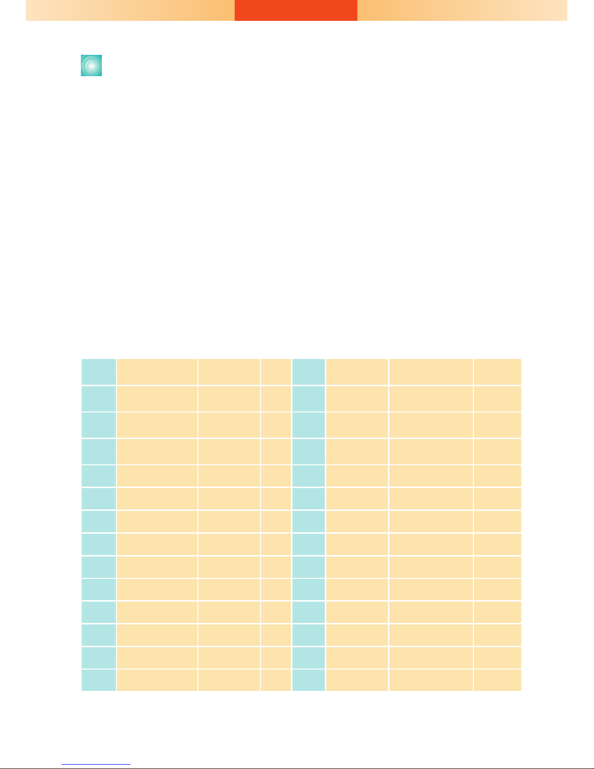
Connector Pin Assignment
Pins Pin Assignment Description I/O(1) Pins Pin Assignment Description I/O
40 +12V~+19V Power - 80 GND Ground -
39 +12V~+19V Power - 79 GND Ground -
38 +12V~+19V Power - 78 GND Ground -
37 +12V~+19V Power - 77 GND Ground -
36 +12V~+19V Power - 76 GND Ground -
35 +12V~+19V Power - 75 GND Ground -
34 +12V~+19V Power - 74 PWR_STATUS PowerGood OUT(OC)(2)
33 +12V~+19V/NC Power/NC - 73 PS_ON# Pluggable Signal ON IN
32 GND Ground - 72 PB_DET Pluggable Board Detect OUT
31 DVI0_HPD DVI-D IN 71 Not Available Not Available I/O
30 DVI0_DDC_CLK DVI-D I/O 70 AZ_LINEOUT_R Audio-R ch OUT
29 DVI0_DDC_DATA DVI-D I/O 69 AZ_LINEOUT_L Audio-L ch OUT
28 GND Ground - 68 GND Ground -
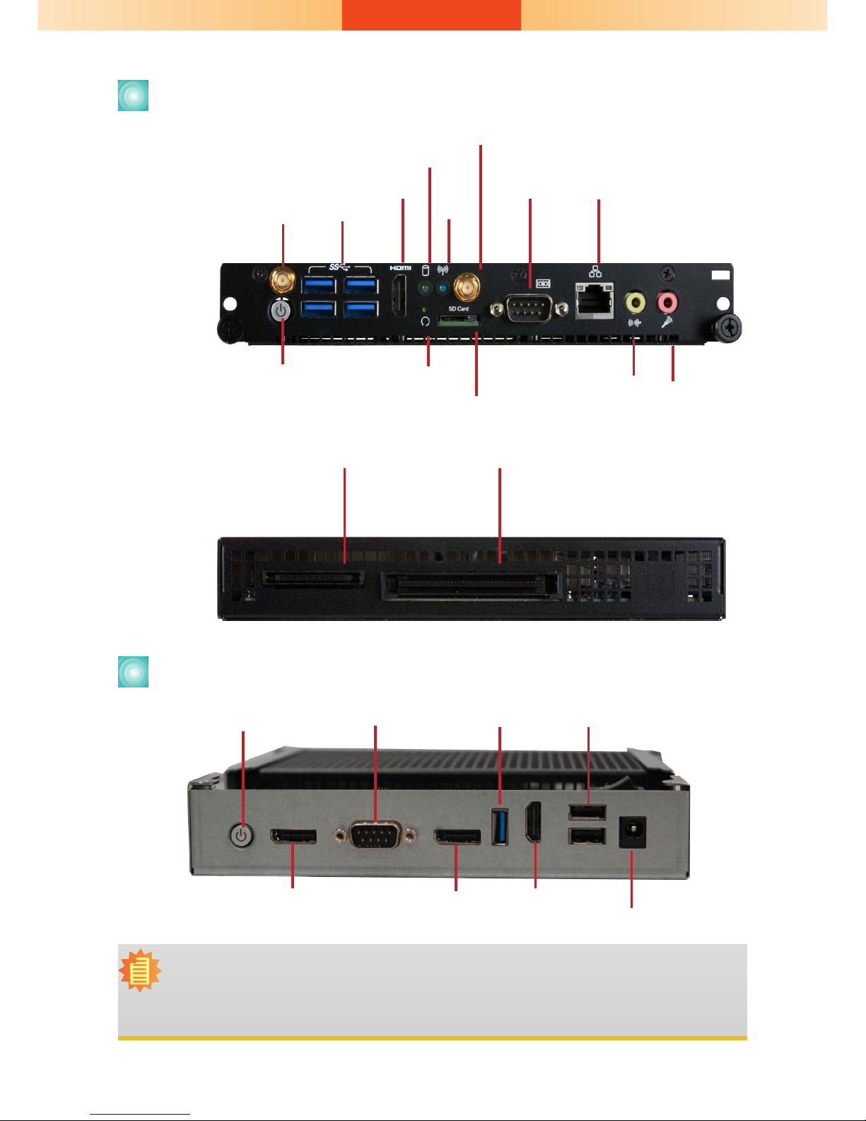
The OPS+ Module enables the integration of a pluggable module and a
display panel by employing the dened interconnect based on the JAE and
HRS combo plug and their receptacle connectors. The right angle blind
mate plug connector (p/n: JAE TX25A-80P-LT-H1E) should be mated with
the receptacle connector (p/n: JAE TX24A-80R-LT-H1E); together, they
provide interfacing for the following functions:
Power: DC-IN +12V~+19V@12A max
Display Interface: 2*HDMI 2.0 (or DVI or DP, 4K at 60Hz)
Audio: left and right Channel
USB: 1*USB 3.0 and 3*USB 2.0
Control and Sensors: 1*UART and Consumer Electronics Control (CEC, note
that the OPS100-SH does not support this function)
Control and Management Signals: the OPS+ Module power status, power-
on via display panel, OPS+ Module detect, Consumer Electronics Control
(CEC), system fan control, and device reset.
The following table lists the pin assignments of the 80-pin JAE connector:

9
27 TMDS0_2+ DVI-D OUT 67 USB_PP0 USB I/O
26 TMDS0_2- DVI-D OUT 66 USB_PN0 USB I/O
25 GND Ground - 65 GND Ground -
24 TMDS0_1+ DVI-D OUT 64 USB_PP1 USB I/O
23 TMDS0_1- DVI-D OUT 63 USB_PN1 USB I/O
22 GND Ground - 62 GND Ground -
21 TMDS0_0+ DVI-D OUT 61 USB_PP2 USB I/O
20 TMDS0_0- DVI-D OUT 60 USB_PN2 USB I/O
19 GND Ground - 59 GND Ground -
18 TMDS0_CLK+ DVI-D OUT 58 StdA_SSTX+ USB3.0 OUT
17 TMDS0_CLK- DVI-D OUT 57 StdA_SSTX- USB3.0 OUT
16 GND Ground - 56 GND GND -
15 DDP_HPD DisplayPort IN 55 StdA_SSRX+ USB3.0 IN
14 DDP_AUXP DisplayPort I/O 54 StdA_SSRX- USB3.0 IN
13 DDP_AUXN DisplayPort I/O 53 GND Ground -
12 GND Ground - 52 UART_TXD UART 3.3V OUT
11 DDP_0P DisplayPort OUT 51 UART_RXD UART 3.3V IN
10 DDP_0N DisplayPort OUT 50 SYS_FAN System Fan Control OUT
9GND Ground - 49 RSVD Reserved -
8DDP_1P DisplayPort OUT 48 RSVD Reserved -
7DDP_1N DisplayPort OUT 47 RSVD Reserved -
6GND Ground - 46 RSVD Reserved -
5DDP_2P DisplayPort OUT 45 RSVD Reserved -
4DDP_2N DisplayPort OUT 44 RSVD Reserved -
3GND Ground - 43 RSVD Reserved -
2DDP_3P DisplayPort OUT 42 RSVD Reserved -
1DDP_3N DisplayPort OUT 41 RSVD Reserved -
Notes:
(1) The I/O column denition is in reference to the OPS+ pluggable board.
(2) OC= Open Collector.

10
The right angle mate plug connector (p/n: FX18-60S-0.8SH) should be
mated with the receptacle connector (p/n: FX18-60P-0.8SH); together, they
provide interfacing for the following functions:
Display Interface: 1*DisplayPort 1.2 (4K at 60Hz)
PCI Express Expansion: 1*PCI-Express 3.0 x4
Control and Management Signals: 1*GPIO, 1*I2C, PHY device management
signals
The following table lists the pin assignments of the 60-pin HRS connector:
Pins Pin Assignment Description I/O(1) Pins Pin Assignment Description I/O
110 DDI1_TXP0 140 Hot Plug - Hot
Plug Detect
109 DDI1_TXN0 139 DDI1_TXP2
108 GND Ground 138 DDI1_TXN2
107 DDI1_TXP1 137 GND Ground
106 DDI1_TXN1 136 DDI1_TXP3
105 GND Ground 135 DDI1_TXN3
104 DDI_AUXP 134 GND Ground -
103 DDI_AUXN 133 GPIO GPIO
102 GND 132 PCIe_RST
101 I2C1_DATA1 I2C Data I/O 131 SLEEP_S3 PHY Status OUT
100 I2C1_CLK I2C Clock OUT 130 LAN_DISABLE PHY Status OUT
99 GND Ground 129 I2C_DATA_LAN I2C/SMBus Data I/O
98 PCIE_CLK_P PCIe CLK OUT 128 I2C_CLK_LAN I2C/SMBus CLK OUT
97 PCIE_CLK_N PCIe CLK OUT 127 GND Ground -
96 GND Ground 126 PCIE-TXP3 PCIe OUT
95 GND Ground -125 PCIE-TXN3 PCIe OUT
94 PCIE-RXP3 PCIe IN 124 GND Ground -
93 PCIE-RXN3 PCIe IN 123 GND Ground -

11
92 GND Ground -122 PCIE-TXP2 PCIe OUT
91 GND Ground -121 PCIE-TXN2 PCIe OUT
90 PCIE-RXP2 PCIe IN 120 GND Ground -
89 PCIE-RXN2 PCIe IN 119 GND Ground -
88 GND Ground -118 PCIE-TXP1 PCIe OUT
87 GND Ground -117 PCIE-TXN1 PCIe OUT
86 PCIE-RXP1 PCIe IN 116 GND Ground -
85 PCIE-RXN1 PCIe IN 115 GND Ground -
84 GND Ground -114 PCIE-TXP0 PCIe OUT
83 GND Ground -113 PCIE-TXN0 PCIe OUT
82 PCIE-RXP0 PCIe IN 112 GND Ground -
81 PCIE-RXN0 PCIe IN 111 PCI_E_WAKE PHY Status IN
Notes:
(1) The I/O column denition is in reference to the OPS+ pluggable board.
(2) OC= Open Collector.
The COM ports on the front panel of the OPS+ Module and the Docking
Board provide serial communication. The following illustrations show the
pin assignments of the COM port:
RS232
COM 1 on OPS100-SH COM 1 on OPS-DB
RTS
RI
DSR
CTS
6 7 8 9
DCD
TXD
RXD
DTR
GND
12 3 4 5
6 7 8 9
TXD
RXD
GND
12 3 4 5
RS232

12
Pins Pin Assignment
3No Connect
2PWM Control
1Ground
Both the OPS+ Module and the Docking Board provide pin headers for
miscellaneous connectors. The following tables list the pin assignments of
these connectors:
Pins Pin Assignment
4Speed Control
3Sense
2Power
1Ground
CPU Fan (OPS100-SH: J1)
GPIO (OPS-DB: J4)
Pins Pin Assignment
2GPIO
1Ground
I2C (OPS-DB: J6)
Pins Pin Assignment
5No Connect
4I2C_Data
3I2C_CLK
2Ground
13V3SB
Pins Pin Assignment
5AZ_LINEOUT_L
4Audio Ground
3AZ_LineOut_R
2No Connect
1No Connect
LPC (OPS100-SH: J7)
Line out (OPS-DB: J5)
Pins Pin Assignment Pins Pin Assignment
7L_AD3 14 5V
63V3 13 5VSB
5L_FRAME# 12 GND
4L_AD0 11 INT_SERIRQ
3L_RST# 10 Key
2L_AD1 9L_AD2
1L_CLK 8GND
SYS Fan (OPS-DB: J3)

13
Physical Dimension
The overall dimensions of the OPS+ Module exclusive of the front panel
frame is 180 x 30 x 119 mm (W x H x D). The following illustrations show
the dimensions of the OPS+ Module as well as the dimension and location
of the front panel screw holes:
200.00
180.00
30.00
2-R2.25
119.00
2-R2.25 91.50
14.50
4.50
5.00 192.00 5.00 23.00
3.00
14.50
4.50
7.00
Other manuals for OPS100-SH
1
Table of contents
Other DFI Desktop manuals

DFI
DFI EC800 Series User manual

DFI
DFI EC533-KD-AI6881 User manual

DFI
DFI EC70B-SU User manual

DFI
DFI EC800 Series User manual

DFI
DFI DT122-SD User manual

DFI
DFI EC800 Series Owner's manual

DFI
DFI ES520-HU User manual

DFI
DFI EMBEDDED ES300 User manual

DFI
DFI DT122-GH User manual

DFI
DFI WM342-KD Series User manual
Popular Desktop manuals by other brands

Asus
Asus Portable AiO P1802-T Series user manual

HP
HP VH677UA#ABA - Pavilion Dv6-1244sb... Product specifications

Dell
Dell Inspiron 5720 quick start guide

HP
HP Pavilion v400 - Desktop PC Technical specifications

Neousys Technology
Neousys Technology Nuvo-6000 Series user manual

AT&T
AT&T PC 6300 Service manual