DFX SOUND VersaLamp 485 User manual
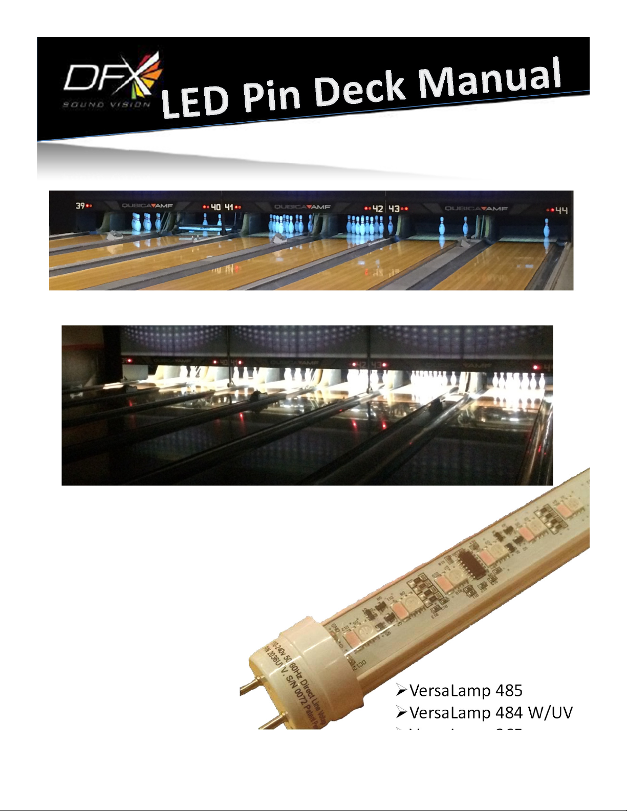
VersaLamp 485
VersaLamp 484 W/UV
VersaLamp 365
VersaLamp 364 W/UV

LED Pin Lighting System
USER MANUAL
2014-2015 DFX. Information subject to change without notice. DFX and all
affiliated companies disclaim liability for any injury, damage, direct or indirect
loss, consequential or economic loss or any other loss occasioned by the use
of, inability to use or reliance on the information contained in this manual.
The DFX logo, the VersaLamp LED Pin Lighting System by DFX logo, the
VersaLamp LED Pin Lighting System by DFX name, the DFX and VersaLamp
names and all other trademarks in this document pertaining to services or
products by DFX, VersaLamp or its affiliates and subsidiaries are trademarks
owned or licensed by DFX or its affiliates or subsidiaries.
All VersLamp LED Light Tubes are Patent Pending.
DFX • 465 Taunton A enue • Suite 108 • West Berlin • New Jersey • 08091 •
USA www.dfxsound ision.com
800-555-5280
Manual Version: C
2

TABLE OF CONTENTS
Safety Information………………………………………………………………...4-6
Introduction………………………………………………………………………….7
Before Installing……………………………………………………………….……8
Physical Installation………………………………………………………….……9
Step #1 First Lane Installation…………………………………………….….10
Installation Of The System…………………………………………………….11-12
DMX Controller………………………………………………………………….….13-14
Figure F: Identify Existing Pin Deck Fixture……………………..…….15
Figure G: Ballast………………………………………………………………....…16
Figure H: Dual 4’ Lamp……………………………………………………..…..17
Figure I: Single 4’ Lamp………………………………………………………….18
Figure J: Dual 3’ Lamp………………………………………………………..….19
Figure K: Single 3’ Lamp……………………………………………..……….…20
Figure W.1 &W.2: Single LED Light Tube Wiring……………………..21
Figure W.3 & W.4: Single Lamp Wiring Example…………………….22
Figure W.5: LED Tube, Fixture with Ballast…………………….……….23
Figure W.6: Dual Pin Deck Wiring Example…………………….…......24
Figure W.7: DMX Wiring Diagram…………………………….…….………25
Figure L: DMX Opto Isolator…………………………………………………..26
Figure M: Drill Template………………………………………………….…….27
DMX Addresser……………………………………………………………………..28-30
DMX Address Tables…………………………………………………………..…31
Troubleshooting…………………………………………………………….........37-40
Programmed Light Shows………………………………………………….….41

4

5

6
•
Do not operate the system with missing or damaged equipment cables.
•Do not lift or carry the LED light fixtures by their DMX cables.
•In the event of an operating problem, stop using the fixture/system immediately and
disconnect it from power.
•Never attempt to use a fixture or systems that are obviously damaged.
•Do not modify the fixtures or system in any way not described in this manual or install
other than genuine LED Light Pin Lights by DFX parts.
•Refer any service operation not described in this manual to a qualified technician.

7
Introduction
The VersaLamp LED Pin Deck Lighting System is a high output LED lighting system that
provides effects lighting for bowling pinsetters/pinspotters. The system uses LED light tubes
with R(red), G(green), B(blue) and/or W(white) and/or UV(ultra-violet) LEDs with DMX
control. See Figures A through D.
The LED light tubes are line voltage 100-240 volt 50/60Hz fixtures. Each LED Light Tube self-
adjusts to correct electric voltage that is being used.
Do NOT connect the LED Light Tube to a ballast!
This will damage the LED Light Tube and will no longer function. This is also not covered by
the warranty.
Each LED Light Tube is addressed with a DMX address. The address of each LED Light Tube
is located on the end cap of the tube (example: ADDR 151). The DMX address is important
because the DMX programming is done with the LED Light Tubes installed in the correct
order. If the tubes are not installed in the correct order the programming will not function
correctly. Each LED Light Tube can be re-addressed with the DMX Address unit.
Each LED Light Tube has a test pattern that is displayed when the DMX Controller is not
connected or powered on.
Here is a list of the test patterns for each LED Light Tube:
VersaLamp 485 – All white LEDs on.
VersaLamp 484W- All white LEDs on.
VesaLamp 484UV – All ultra-violet LEDs on.
VersaLamp 365 - All white LEDs on.
VersaLamp 364W – All white LEDs on.
VersaLamp 364UV – All ultra-violet LEDs on.
The key pad DMX control unit is programmed with ten light shows (See Figure E & E.1). The
LED Light Tubes. Custom programming can be done through the PC control software.
The system includes: LED Light Tubes, pre-programmed DMX Controller, DMX control
cables, Light Tube Addresser and in larger systems a DMX Opto Isolator (Figure L).

8
Before using the product for the first time
1. Read “Safety information” before installing, operating or servicing the fixture.
2. Read at a minimum the “First Lane Installation” instructions before
installing.
3. Unpack and ensure that there is no transportation damage before using the fixture.
Never attempt to operate a damaged fixture.
4. Before operating, ensure that the voltage and frequency of the local power source
match the power requirements of the fixture.
5. Check the LED Pin Deck Lighting System support pages on the DFX website at
www.dfxsoundvison.com for the most recent user documentation and technical
information about the system.

Physical installation
Warning! Read “Safety information” before installing
the system.
•The fixture is designed for indoor use only and must be used in a dry location with
adequate ventilation.
•Do not stand LED Light Tubes on a surface or leave it where it can be moved or fall
over.
•Some scoring systems may not be able to properly score when the light show is
operating. Test the system on one lane first. This includes testing that the scoring
system can properly score when the light shows are on and running. If the scoring
system does not properly score do not install the rest of the LED light Tubes until
the first lane is working properly. This may require adjusting the scoring system to
operate in lower light le els. Contact the scoring system manufacturers with all
scoring systems questions. DFX technical support can only pro ide support for the
LED Pin Deck Lighting System.
9

10
STEP #1!!!!
First Lane Installation
1. Test the light system on one lane first before installing all of the LED
Light Tubes. Some scoring systems may not be able to properly score when
the light show is operating. This includes testing that the scoring system can
properly score when the light shows are on and running. If the scoring system
does not properly score do not install the rest of the LED Light Tubes until the
first lane is working properly. This may require adjusting the scoring system to
operate in lower light levels. Contact the scoring system manufacturers with all
scoring systems questions. DFX technical support can only provide support for
the LED Pin Deck Lighting System.
2. On the back of the DMX Controller connect the power supply and the DMX
output cable. See Figure E.1.
3. Shut down the electrical power and lock-out the first bowling
pinsetter/pinspotter the lighting system is to be installed on. Generally, the
fixtures are to be installed left to right.
4. Be sure the LED Light Tube are all installed with the same orientation or DMX
cables on the same side of the pin deck fixture.
5. Identify the type of existing pin deck light fixture in your pinsetter/pinspotter.
See Figures H through K.
6. Follow the applicable directions to by-pass the ballast of the fluorescent light
fixture you will be replacing and wire the lamp sockets (tombstones) direct to the
line-voltage. See Figures W.1 through W.6.
7. Place included warning label on light fixture so the next technician to work on
the light fixture is aware that the ballast has been by-passed.
8. Press playback button #4 for VersaLamp 485 & 365 systems and play back button
# 3 for VersaLamp 484 & 364 systems on the DMX controller. This will play a fast
color change on the LED light tube. See Figure E.
9. With the light tube on and working, optimize the focus of the light tube.
10. With all of the cables and the controller secured and out of the way of the
pinsetter/pinspotter moving parts, bowl several frames to thoroughly test the
scoring system.
11. If the scoring systems operates and scores correctly, press playback #1 of the
controller. This is a white or ultra-violet light output depending on the fixture
type used.
12. Again, bowl several frames and thoroughly test the scoring system.
13. If the scoring system operates correctly then continue with the installation of
additional lanes. If not, then troubleshoot the issue with the Troubleshooting
section of this manual.

11
Installation of the System
1. Remove power from the first pinsetter/pinspotter and lock-out the machine.
2. Disconnect the controller from the light tube and remove all cables used to test the
first light tube.
3. If your installation is more than ten lanes for VersaLamp 485 & 365 systems a DMX
Opto Isolator is to be installed. If your installation is more than twelve lanes for
VersaLamp 484 & 364 systems a DMX Opto Isolator is to be installed. This is to be
installed in the middle of the lanes on the back side of the curtain wall. See Figure
L.
4. Permanently install the controller at the desired control position. Generally, it is
installed at the control desk or equipment rack.
5. Install the main DMX control cable from controller to the DMX Opto Isolator for
larger installations (more than ten lanes) or to the first LED Light Tube fixture for
smaller installations (ten lanes or less).
6. If a DMX Opto Isolator is used, install the DMX cable from output #1 of the splitter to
the first LED Light Tube. Be sure to secure all cables so that they are not in contact
with any moving parts of the pinsetter/pinspotter.
7. Then test the first lane again and bowl several frames to confirm the scoring system
is scoring correctly.
8. If the scoring system is scoring correctly, shut down the electrical power and lock-out
the first bowling pinsetter/pinspotter and the next pinsetter/pinspotter the lighting
system is to be installed on. Generally, the fixtures are to be installed left to right.
9. Follow the directions to by-pass the ballast of the pin deck light fixture for your
applicable existing fluorescent light fixture and wire the lamp sockets (tombstones)
direct to the line-voltage. See Figures W.1 through W.6.
10. Place included warning label on light fixture so the next technician to work on the
light fixture is aware that the ballast has been by-passed
11. Install the second LED Light Tube. Be sure the LED Light Tube is the correct address.
Refer to the DMX Address Table to confirm the address. The light tube is to be focus
to the center of pin #1. Depending on the fixture the lamp sockets of the light fixture
may need to be adjusted to properly focus the light tube. For many light fixtures, it is
possible to rotate the light tube in the lamp sockets. For spring loaded lamp sockets,
it may be necessary to remove the screws from the lamp socket and drill new holes
in the fixture case to be able to properly rotate the new LED Light Tube. Refer to the
template page of this manual.

12
12. Connect the DMX cables from the first light tube to the second light tube using the 15’
DMX cable and connect to the male XLR connector of the next Light Tube. Be sure all
cables are secure and away from all moving parts of the pinsetter/pinspotter.
13. Then test the both lanes again and bowl several frames to confirm the scoring system is
scoring correctly.
14. If the scoring system is scoring correctly, then continue installing up to ten or twelve
lanes depending on the model of the LED Light Tube being installed. Or ten to twelve
LED Light Tubes depending on the model being installed on the same feed from the
DMX Opto Isolator. Please refer to the low voltage wire diagram for the size of your
installation. If the scoring system is not scoring correctly or the LED Light Tubes are not
working properly please refer to the Troubleshooting section of this manual.
15. Once the LED Light Tube fixture limit is reached, it is time to install the next DMX cable
from the DMX Opto Isolator output #2 to the next set of LED Light Tubes.
16. Then continue installing and testing the LED Light Tubes and scoring system as you go.
Be sure all cables are secure and away from all moving parts of the
pinsetter/pinspotter.
17. Be sure to follow the included DMX wiring diagram. See Figure W.7.
18. Upon completion of the installation, thoroughly test the system. If there are any issues
please refer to the Troubleshooting section of this manual.

DMX Controller
13
Figure E
DO NOT USE THE INTENSITY & SPEED BUTTONS!!!!
THESE WILL CAUSE THE LED LAMPS TO BE OVER
DRIVEN AND DECREASE LAMP LIFE!!!!!!!!!

14
DMX Controller
Figure E.1

Figure F: Identify existing pin deck fixture
4 Types:
15
a) Dual lamp 4’
b) Single lamp 4’
c) Dual lamp 3’
d) Single lamp 3’
Fig F.1
Fig F.2
Fig F.3
Fig F.4
WARNING: DAMAGE/VOID WARRANTY DO
NOT PLUG INTO EXISTING FIXTURE WITH
BALLAST BYPASS
4’
4’
3’
3’
NOTE: MACHINE POWER
SHUTDOWN DURING ENTIRE
INSTALLATION.

Ballast Example
16
Figure G

Dual 4’ Lamp
Rewiring existing fixture to accommodate LED tube
fixture.
1. LED tube fixture is to replace the UV/Blacklight tube
not existing fluorescent white tube
2. Ballast must be bypassed allowing 110-240AC to the
existing fixture ends (tombstones) (see illustration W.5)
17
NOTE: MACHINE POWER
SHUTDOWN DURING ENTIRE
INSTALLATION.
WARNING: DAMAGE/VOID WARRANTY DO
NOT PLUG INTO EXISTING FIXTURE WITH
BALLAST BYPASS
Figure H: Wiring

Single 4' Lamp
Rewiring existing fixture to accommodate LED tube
fixture.
1. LED tube fixture is to replace the existing fluorescent
white tube
2. Ballast must be bypassed allowing 110-240AC to the
existing fixture ends (tombstones) (see illustration W.5)
18
Figure I: Wiring

Dual 3' Lamp
Rewiring existing fixture to accommodate LED tube
fixture.
1. LED tube fixture is to replace the UV/Blacklight tube
not existing fluorescent white tube
2. Ballast must be bypassed allowing 110-240AC to the
existing fixture ends (tombstones) (see illustration W.5)
19
Figure J: Wiring

Single 3' Lamp
Rewiring existing fixture to accommodate LED tube
fixture.
1. LED tube fixture is to replace the existing fluorescent
white tube.
2. Ballast must be bypassed allowing 110-240AC to the
existing lamp sockets (tombstones) (see illustration W.5).
20
Figure K: Wiring
This manual suits for next models
3
Table of contents