DH Antenna GIBRALTER GE-MINI User manual

CRITICAL FACTORS
INSTALLING A DH ANTENNA
1. READ INSTRUCTIONS before disassembling the crate.
2. RIBS: Look for color coded dot on the rib. Dots indicate correct order
to assemble panels. Number is stamped in the lip of the antenna too.
3. PILOT HOLE: Locate pilot hole on the ring and antenna. THIS IS
YOUR STARTING POINT! Pilot hole is located on the 2nd block from
the left of the weld on the ring from the back view of the antenna.
MATCH mount pilot hole to panel with pilot hole.
4. FINGER TIGHT: Installing the panels to the ring and installing the
ribs on the panel sections. DO NOT OVERTIGHTEN.
5. TIGHTEN DOWN all ribs to become a solid antenna. (Once all panels installed)
6. STRING THE ANTENNA. Strings should just touch. Adjust the
braces so front surface is exactly flat.
7. TIGHTEN DOWN ALL BOLTS: Ring to antenna.
8. SET FEEDHORN TO EXACT FOCAL LENGTH & TO EXACT
CENTER OF THE ANTENNA. Use a laser tool or cut a piece of wood
to the focal length of your antenna. Feedhorn must be flat to antenna
surface. Please consider feedhorn manufacturer’s recommendation. See
“Preparing the Feed Assembly” in manual.
CALL 1-608-326-8406 WITH QUESTIONS
Congratulations! You have now purchased the finest Dual Powered Azimuth-Elevation Mount
available. This unit will not only track the geosynchronous arc, but will work equally well for
satellites that are in inclined orbit, or elliptical orbit. Please follow these instructions. You may
call us at 608/326-8406 for help, Monday – Friday 7AM to 5 PM CST. Please review the
shipping warranty for missing parts immediately upon arrival (see back page).
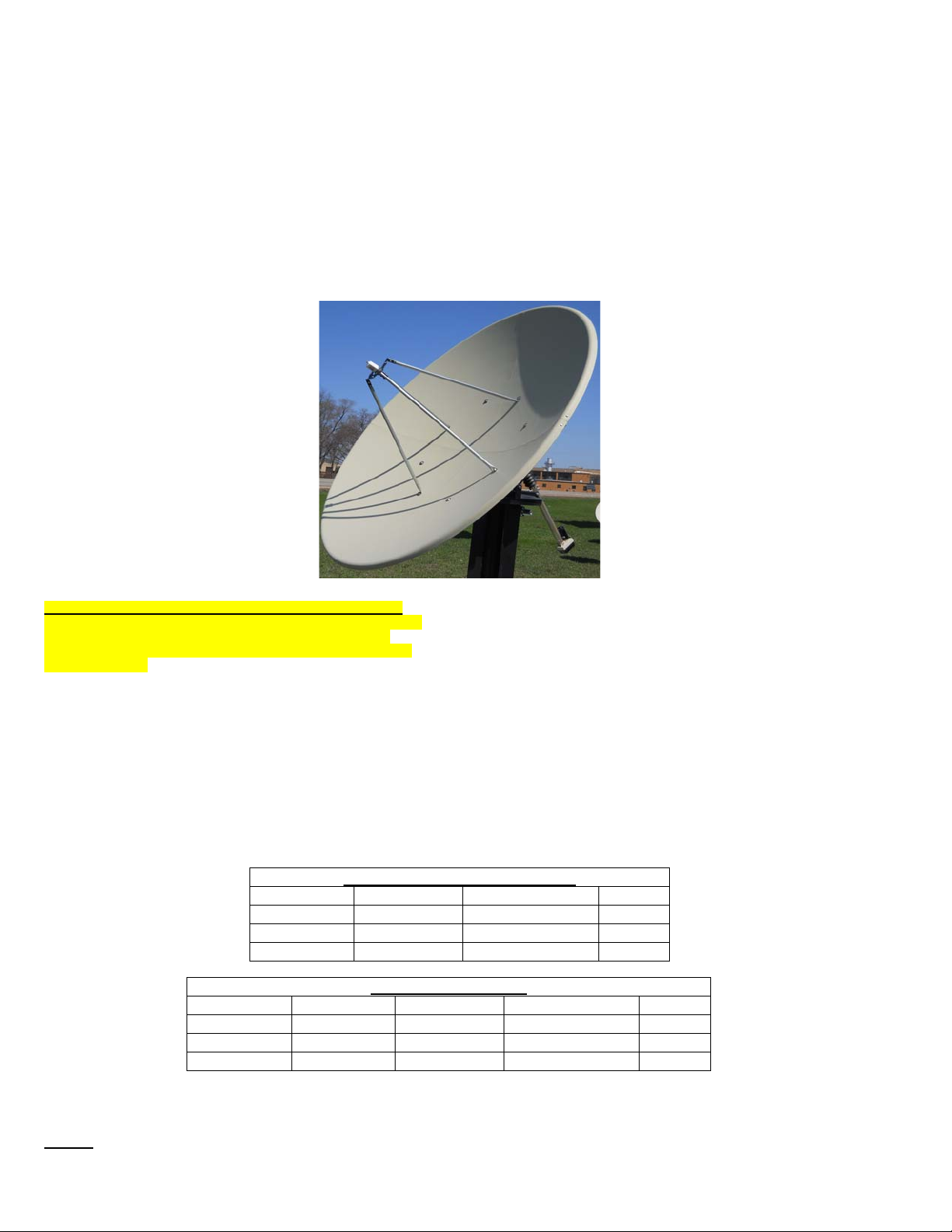
The Ge-mini is designed to go with the 2.4m, 2.7m, and 3m antenna from DH. The 2.4m and the
3m are identical in theory with the exception of the 3m having a 48” ring with eight back braces.
We will cover the basic installation first and address each individually as the installation
requires.
PLEASE READ COMPLETE INSTRUCTIONS BEFORE BEGINNING INSTALLATION!!
www.dhsatellite.com
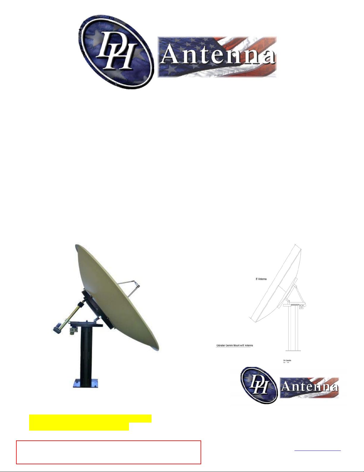
4PC Sectional Antenna Gibralter GE-MINI
Installation Instructions
PO BOX 239
600 N MARQUETTE RD
PRAIRIE DU CHIEN WI 53821
PHONE: 1 (608) 326-8406
FAX: 1 (608) 326-4233
EMAIL: [email protected]
CAUTION: Your 3m antenna will have 8 back braces.
Please be sure to string your antenna at time of installation.
Sectional antennas must be handled with care not to twist
or distort sections while handling for installation. 12/18/2017
*Galvanizedbackbracespleaseimmediately
readspecialnoteonboltbagpage2.
Parts List for: The “Dual Powered Ge-mini”
Elevation Assembly
1- 18" Actuator w/HD Clamp
1- 1/2" x 4 1/2" Bolt
1- 1/2" x 2" Bolt
2- 1/2" Lock Washers
2- 1/2" Nuts
Back Braces
3.0m w/48” Ring
(Optional on 2.4m & 2.7m w/39” Ring)
8- Back Braces
8- Brace Clips
8- Bent Tabs
8- ½” x 1 ½” Bolts
24- ½” Nuts
8- ½” Lock Washers
8-3/8" x 1 ½” Bolts
8-3/8" Nuts
8- 3/8” Lock Washers
16- ¼”x ¾” Bolts
16- ¼” Nuts
16- ¼” Lock Washers
PAGE 2
Base Plate Template Kit
(Optional)
4- 3/4" x 18" J-bolts
4- 3/4" Nuts
1- Wood Template
Antenna to Ring
39” & 48” Ring 8 Block
8- ½” x 3” Bolts
8- ½” Lock Washers
8- ½” Nuts
8- ½” Flat Washers
16- ½” Rubber Washers
C14F
Chaparral
Feed Assembly
1- Set of 4 Struts
1- Collar (C, Ku)
8- ¼” x 1 ½” Bolts
8- ¼” Lock Washers & Nuts
Ku4FL: 3PC
Add to C14F
3- Section to 3pc collar
3- 8-32 x 1” Bolts
3PC Collar for Ku4FL
(Use to Attach to Horseshoe of C14F)
3- 8-32 x ¾” Bolts
3- #8 Fender Washers
3- 8-32 Nuts
Mount to Ring
2- 1/2" Lock Washers
2- 1/2" x 2 1/2" Bolts
2- 1/2" Nuts
2- 1/2" x 3/4"x 1/2" Long Brass Bushings
NOTE:
Stainless steel or DURA-CON® hardware provided.
*DURA-CON® is a corrosion resistant coating.
DURA-CON®: Problem of thread-galling is eliminated.
NOTE: SECTIONAL ANTENNAS INCLUDE ADDITIONAL
HARDWARE, SEE TABLES BELOW
Template Rib Hardware: Sectional
Antenna Size ¼” x ¾” Bolts ¼” Lock Washers ¼” Nuts
2.4M 36 36 36
2.7M 40 40 40
3.0M 44 44 44
Splice Straps: Sectional
Antenna Size Splice Straps ¼” x ¾” Bolts ¼” Lock Washers ¼” Nuts
2.4M 4 8 8 8
2.7M 4 8 8 8
3.0M 4 8 8 8
Heavy Duty Feed
Struts
C14F or C24
1- Set of 4 Struts
1- Collar (C, Ku)
12 - 5/16” Lock Washers & Nuts
4- 2' x 2' Angle Brackets
4- 5/16” x 1 ½” Bolts
*Highly Recommended On Systems With Galvanized Back Braces*
Please use a rubberized spray or silicon sealant to coat the threaded rods on
the end of back braces to help prevent corrosion. When doing annual
maintenance on your antenna system please make sure to check as it may
need to be reapplied.

3/8" x 39" Ring
Gemini 39" Azel Mount & Fixed Mount
DH SATELLITE
PRAIRIE DU CHIEN, WISCONSIN 53821
PHONE (608) 326-8406
P.O. BOX 239
DESCRIPTION:
DRWN BY: DATE;
SCALE: REVISED:
DRWG#:
GILBERTS 1-27-15
NOT TO SCALE
39AZELMT wblocks
weld
22.5°
45.0° 45.0°
2" 1/2"
1 1/2"
2"
17/32" Hole
End Side
Top
Tabs
14 1/2"
3/4"
38 1/2"
1/4" x 3" Fins
1/2" x 18" x 18" Plate
3/16" x 2" Dust Shroud
Motivario Gearbox
Chain Drive
16" 20"
12"
6 1/2"
4"
1 1/2"
3/4"
2"
2"
1/8" x 2" x 2" x 40" Square Tube
1/8" x 2" x 2" x 32 1/2" Square Tube
1/8" x 2" x 2" Square Tube
2"
5 3/4"
5 1/4"
1 1/4" Hole
1/8" x 2" x 2"x 30 1/2" Square Tube
1/4" x 2" x 2" x 19" Square Tube
Galvanized Tin Shroud
10 1/2" x 17 3/4"
Front Shroud 5 1/4" deep x 20 1/4" Long
4"
1 3/4"
3/8"
17/32" Hole
31 1/4"
1/8" x 2" x 2" Square Tube
T- Top
Tab
Top Plate
Wear Plate
Bottom Plate 1/2" x 23 1/2"
Bottom of T-
Top
Side
19"
5 1/4"
17/32" Hole
1/4" 2" x 2" Square Tube
3/4"
5 1/2" x 48" Sch. 40
Gibralter Gemini Dual Az-El Mount
3/4"
1/2"
3/4" Hole
2" 2"
18"
18"
1 1/4" Holes
Gemini Base Plate
1/4 x 3" Fins full length
12"
3"
3"
6" O.D. Pipe
3/16" Wall
3/4" x 1 1/2" Set Screws (4)
8 1/2"
8 1/2"
Stow Bar End Tab
5/8"
2"
1/2"
17/32" Hole
Stow Bar End Cap
2 1/4"
30"
1 7/8" x 30" Tube
1/2"
1"
1/4"
2"
17/32" Hole
1"
17/32" Hole
1/2"
1 3/4"
3"
1/2"
Gibralter Gemini Fixed
6"
4"
10"
Fins made from 1/4 x 4"
39" Ring w/blocks
PAGE 3

INSTALLATION OF BASE
Look at the drawings below. Figure #1 shows a typical recommended concrete base. This base
should be a minimum of 3’0”x3’0”x 3’0” deep for 2.4m antenna. In areas of frost, we
recommend that this base go below frost levels. You can (depending on soil type) opt to use ½”
rebar to reinforce this structure. Contact your local concrete dealer or a local engineer to give
you an idea if you should use rebar for your locality. WE RECOMMEND THAT YOU CHECK
WITH A LOCAL ENGINEER TO DETERMINE SOIL TYPE AND BEARING TO VERIFY THAT THIS
BASE WILL WORK FOR YOUR LOCALE.
When pouring the concrete, be sure to have the base template ready and insert the J-bolts as per
Figure #2. Leave approximately 2” of the bolt out of the concrete. These bolts can be installed
after the mount is delivered; by drilling the holes in the concrete and using either lead heads or
Garonite, (A resin mortar) to secure the bolts. If you decide to put the bolts in after the concrete
has set, you must install regular hardened bolts or cut the bottom of the J-bolts. (We recommend
the bolts be installed prior to the delivery of the mount). Our people have installed both lead
heads and Garonite, we recommend the Garonite.
When installing the Gibralter Gemini stand, carefully lower it over the bolts and tighten the
nuts in place. (The gearbox should be on the North side of the mount in the Northern Hemisphere and on the
South side of the mount for the Southern Hemisphere.) Be sure to install a lock washer. It is always a
good idea to get the base plumb, although this is not critical with this Azimuth-Elevation mount
as it would be a polar mount. The front of the mount should be facing south in the Northern
Hemisphere. (The rear of the mount will have the gearbox). With the Gibralter Gemini mount,
you will have over 250 degrees of travel, but you do not have a full 360 degrees of azimuth. I
mention this for those of you who are installing the Gibralter Gemini to track things other than
the Geosynchronous Satellite belt.
Fig. #1
Fig. #2
PAGE 4
Assemble Ring to Base Stand (for the 2.4m & 2.7m)
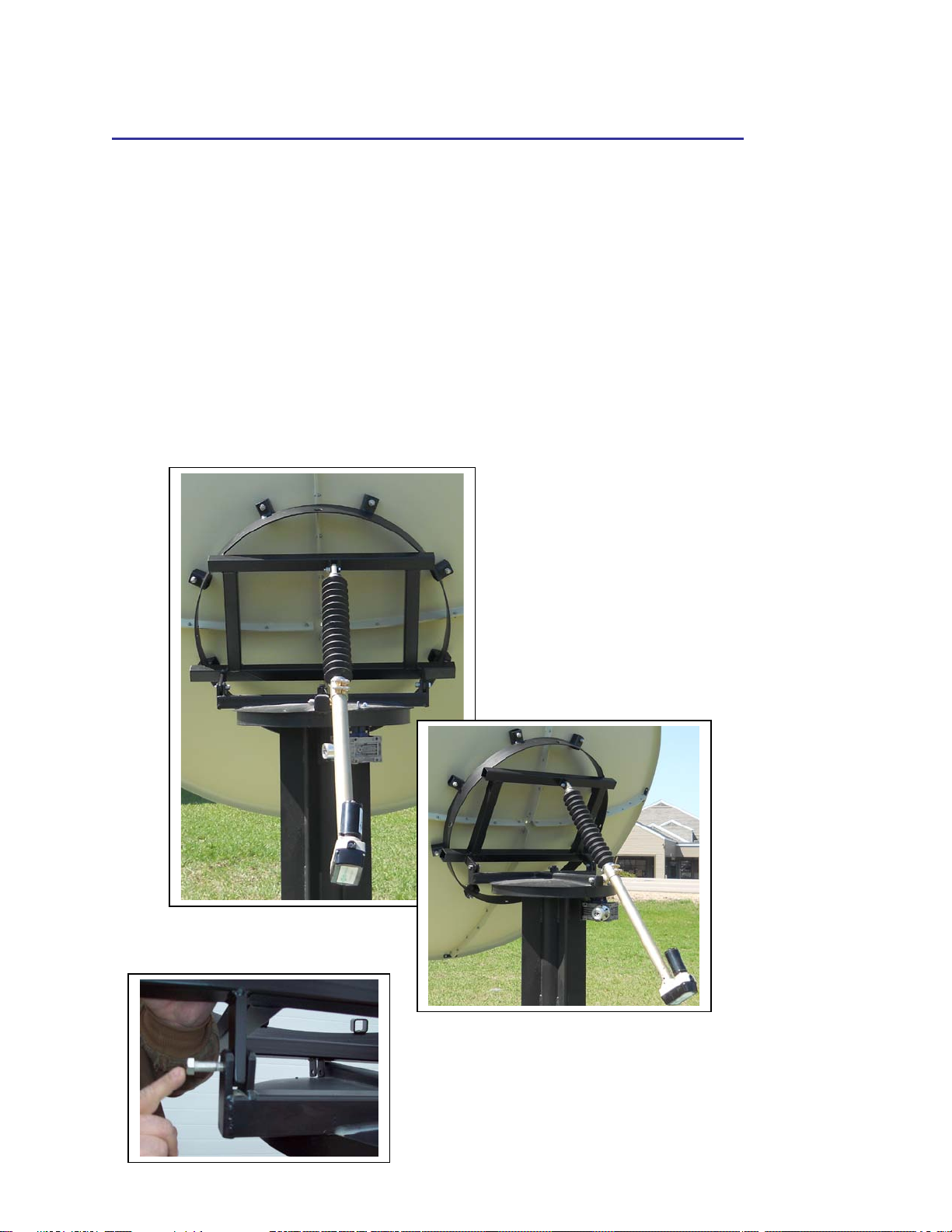
You will have to assemble the 39” ring to the Ge-Mini base. Look at the photo of
the mount in Fig. #3, you will notice that the top of the mount has a bracket to
attach the elevation arm. The bottom of the 2” framework has two tabs. Insert a
½”x ¾” x ½” long brass bushing (found in the bolt bag) into each of the tabs.
Place the ring on the base stand, inserting the tabs (with the bushing) into the
double ear tabs. Secure with ½” x 2 ½” bolt, ½” lock washer & nut. Next install
the elevation actuator. Attach the gimball actuator clamp to the right side rear of
the 2” square tube with a ½” x 4 ½” bolt. Then take the eyebolt on the end of the
actuator and put it in between the top bracket of the frame work of the ring. Use a
½” x 2” bolt and use a lock washer and nut to secure it in place. This elevation
actuator will be used to precisely aim the dish to the satellite you are using.
PAGE 5
Please see the parts listed supplied to
help identify all parts for both the
Dual Powered Ge-Mini and the Fixed
Az-El Ge-mini. You will find these
drawings on the previous pages of
this instruction manual. Note the
Fixed Az-El Ge-Mini does not
include the motors or gears and
drives. These parts are only used for
the Dual Powered Ge-mini.
Fig. #3

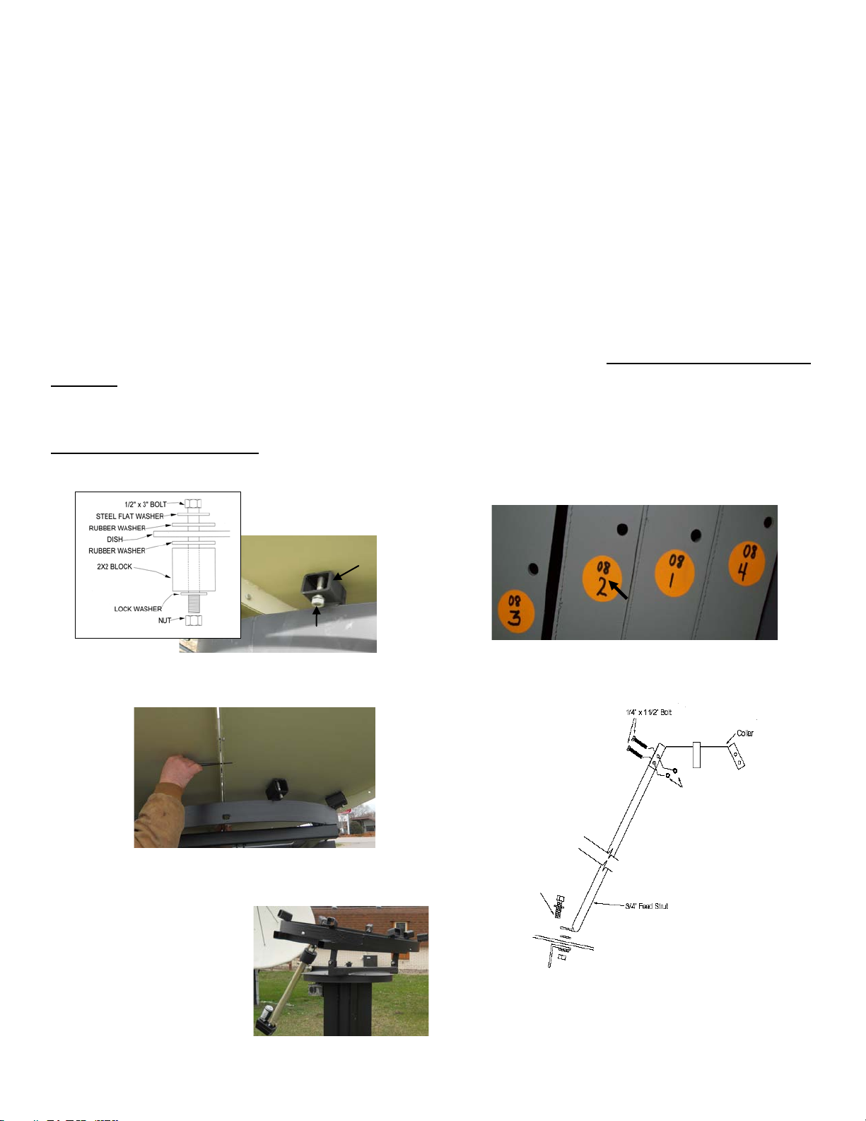
ASSEMBLING THE ANTENNA TO THE RING
The mount should be assembled and now it is time to install the antenna. We recommend two methods of lifting the
antenna onto the post. SPECIAL NOTE: A 2.4m and 2.7m use a 39” ring and a 3.0m uses a 48” ring.
1st Option: (On Ground: Lifting the Antenna as One Piece)
The antenna will come in 4 pieces each having a color coded dot on the rib (see FIG. #9). NOTE: After complete
installation you will no longer see the colored dots. You must take two sections of the antenna and place them on a flat
surface face down allowing for an installer to work on attaching the numbered ribs. The antenna must always stay in the
crate until assembled. (see FIG. #10). Take panel one labeled 08/1 and 08/2 and attach it to panel 2 which is labeled 08/2
on one rib and 08/3 on the other rib. Connect panel 1 with rib #2 (labeled 08/2) to panel 2 with rib #2 (labeled 08/2),
matching the #2 on each rib of the two panels (See photos below). Install 1/4" x 3/4" bolts in all holes, finger tight. To
allow for greater ease in aligning the templates we recommend using an alignment punch tool (See Figure #11).
IMPORTANT: Do not force or drill any ribs to make them fit. Doing so will void your warranty and the dish will
not perform. Once you have the bolts inserted into the template holes, attach the splice straps to the inside lip of the
antenna (See FIG. #12 ). Continue on to the next panel in the same manner until finished with all panels. Now tighten all
hardware.
Next lift up the antenna and have the smallest worker go underneath the dish. You will then place the ring on the
antenna, making sure that the two pilot holes correspond. One is located next to one of the 8- ½” holes in the dish and
other is found on one of the 8 blocks on the mount next to the ½” holes. The pilot holes are just locators for aligning the
holes on the dish with those on the mount. The weld on the antenna is lined up with the boom on the mount. Have the
worker underneath the antenna insert the bolts up through the dish. On the other side have another worker attach the
rubber washer, lock washer and nut. Please do not tighten nuts at this point. After all bolts have been inserted have
the worker underneath come out from under the dish. If you purchased an antenna with back braces attach them now and
tighten down all bolts. You can now lift the antenna and ring by a crane, forklift or a boom truck. This insures that no
pressure will be put on the antenna.
FIG. #9
FIG. #10
Match 2 with 2
Rib
The top number represents the serial number of the antenna. *Example: In FIG. #9 you will see 4 sections with the
top number 08. You will take all four pieces of 08 to make one complete antenna.
Rib number. *Example: On a 4 piece 3.0m antenna the dot will have a 08 on the upper part of the dot
(serial number) and the lower number of 1, 2, 3, 4 are the rib numbers.
FIG. #11
Splice Strap
FIG. #12
Alignment
Punch
PAGE 6
NOTE:
The aluminum antenna is also stamped in the lip. This number
reflects the position of the panel.
The number stamped on the rib reflects the antenna as a whole for
bulk shipping. Each section has one rib stamped. The number will
be the same on all ribs making it one complete antenna.
2nd Option: Bird Bath Method, installing by sections with BACK BRACES.
(Using 2-3 People)
*IMPORTANT: If you purchased an antenna without back braces continue to page 8.
Assemble mount and put mount in birdbath position (See picture C below).
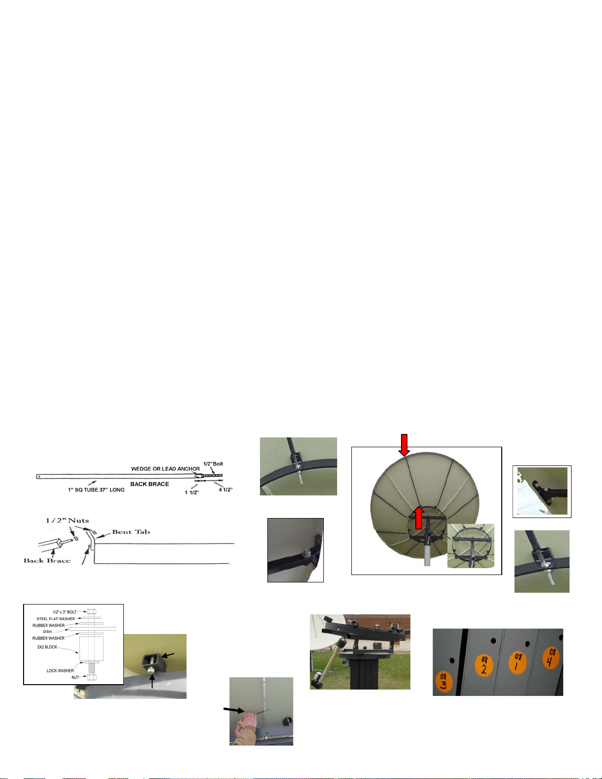
Step 1: Install the brace clips to the back braces before placing on the antenna lip and ring. Have all 4 brace
clips installed on the brace before going to the next step. See brace clip and back brace photos below.
Step 2: Install brace clips to the ends of the 4 back braces and install the ½” nut on the threaded rod end of the
back brace, threading it down approximately 4 to 4 ½” down the threaded rod (see FIG. #13).
Step 3: Take the first panel and install it to the ring of the mount finger tight. Be sure to find the pilot hole on
the mount and on the antenna. Take the back brace that is ready and put the threaded rod through the tab on the
ring (see photo A). Take the other end of the rod with the clip and attach the brace and clip to the lip of the
antenna section (see picture B).
Step 4: Insert ½” x 3” bolt (see FIG. #17 for washers and rubber placement) from the antenna to the mount.
Have one person continue holding the panel in place while the second person attaches the back brace.
(Remember the threaded end of the back brace should already have the ½” nut on the threaded end about 4-4 ½”
on the threaded rod and the bent tab already installed on the ring, see FIG. #15). Insert the threaded rod of the
back brace into the bent tab and bolt brace clip on the edge of the antenna with 3/8” x 1 ½” bolt, 3/8” nut and
3/8” lock washer. Make sure everything is finger tight.
Step 5: Pick up the second antenna panel and be sure the numbers line up and bolt in place just like the first
panel. (see FIG. #9) Once secure you can begin bolting the two units together by placing the ¼” x ¾” bolts
through the templates. Again only finger tight. Continue for the next 2 panels. To allow for greater ease in
aligning the templates we recommend that you use an alignment punch tool. (see FIG. #10).
STEP 6: You will notice all 8 bolts in the face of the antenna have been installed from the antenna to the ring at
this point. You now remove every other bolt from the face of the antenna and replace them with a feed strut.
(See preparing the feed assembly on page 10)
FIG. #13
PICTURE A
PICTURE B
FIG. #17
FIG. #15
Back braces are measured by tube length only.
PAGE 7
FIG. # 9
Brace Clip
Brace Tab Threaded
PICTURE C
PICTURE AA
1/2” x 1 1/2" Bolt
Match 2 with 2
FIG. # 10
Alignment
Punch
Block
1/2” x 3” Bolt
Bird Bath Method, installing by sections NO BACK BRACES.
(Using 2-3 People)
Assemble mount and put mount in birdbath position (See picture C below).
Step 1: Take the first panel and install the ½” x 3” bolt from the antenna to the mount finger tight (see FIG. #9
for washer and rubber placement). Be sure to find the pilot hole on the mount and on the antenna.
Step 2: Pick up the second antenna panel and be sure the numbers line up and bolt in place just like the first
panel (see FIG. #10). Once secure you can begin bolting the two units together by placing the ¼” x ¾” bolts
through the templates. Again only finger tight. Continue for the next 2 panels. To allow for greater ease in
aligning the templates we recommend that you use an alignment punch tool (see FIG. #11).
Step 3: You will notice all 8 bolts in the face of the antenna have been installed from the antenna to the ring at
this point. You now remove every other bolt from the face of the antenna and replace them with a feed strut.
Use this sequence: bolt, metal washer, feed strut, rubber washer. On the backside of the dish, insert a rubber
washer between the dish and the ring block, followed by a lock washer and a nut. Please do not tighten nuts at
this time.
Step 4: Next install the feed collar (C14F collar) into the feed struts. Secure with 8- ¼” x 1 ½” bolts and ¼”
lock washers and nuts. (see FIG. #12). Your next step is to tighten the 8 bolts that secure the dish to the ring.
DO NOT OVER TIGHTEN. This is also addressed in Preparing the Feed Assembly on page 10.
FIG. #10
Match 2 with 2
FIG. #9
FIG. #12
PICTURE C
FIG. #11
PAGE 8
¼” Lock Washers & Nuts
Block
1/2” x 3” Bolt
½” x 3” Bolt
½” Steel Washer
½” Rubber Washer
Antenna Surface
½” Rubber Washer
½” Lock Washer
½” Nut
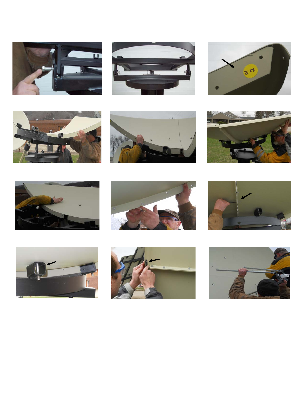
Installation Photos:
Additional Help for Installing by Sections to the Ring
Template Rib
Block
Splice Strap
Alignment Punch
PAGE 9
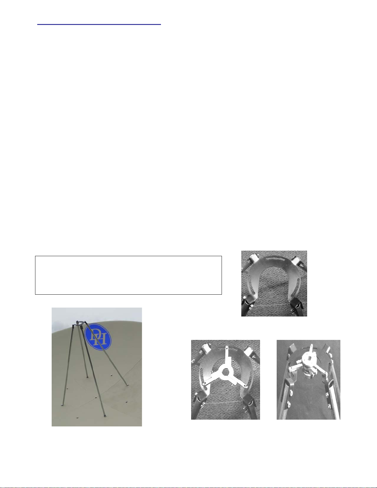
Preparing the Feed Assembly
If the feedhorn you have selected has an adjustable scalar ring, move it to the proper wave-guide setting.
The 2.4M, 2.7M, and 3M antennas all have the same f/l. The F/D ratio is listed below for each. Be
sure to measure from the center of the dish to the throat of the feedhorn when using a Chaparral
style feed. You should be measuring 35 ¾” from the center of the dish to the throat of the feedhorn
for C band. Ku band is more critical so please if using a C/Ku band feedhorn to error on setting it up
for measuring the Ku which would be 35 7/8” from the center of the dish to the throat of the
feedhorn. Major adjustments for Ku band can be made by placing the three-piece collar on
either side of the horseshoe collar.
Special note: Seavey feeds are measured to the scalar ring and not the throat.
Unless you have specified what brand name and frequency your feedhorn is, you will have received by
default the C14F collar. It is best if you have discussed with your sales rep the feedhorn you are using prior
to shipping so that DH Satellite can make sure you have the proper collar to mate to your feedhorn. You do
need to make sure your feedhorn and collar are the correct combination.
Take the scalar ring of the feedhorn and place it under the collar with rings pointing toward the dish. Turn
it until all three holes line up between the two and insert the ¼” x ¾” bolts through the scalar ring and then
through the collar; fasten with the ¼” nuts. Most C-band and dual feeds have a 3-bolt pattern on the scalar
ring just for this. Tighten all nuts and bolts. Figure #7 is the final assembly for the Ku band showing a Ku
straight through feedhorn being used.
Check to see that the feed is at the focal length, the actual focal length should be ¼”
inside the wave-guide, for C-band and 1/8” for Ku band.
8' 35 ¾” Focal Length - .375 F/D - Wave Guide 9/16”
9’ 35 ¾” Focal Length - .33 F/D -Wave Guide 5/8”
10’ 35 ¾” Focal Length - .3 F/D -Wave Guide 7/8”
KU4FL
FIG. #6
PAGE 10
FIG #7
C14F COLLAR AND STRUTS
Strut Local on Ring Face of 4PC Sectional
Antenna 8 Block Ring

HeavyDutyFeedStrut________________________
Wehavedevelopedanewfeedstrutandcollarforthe
heavier4PortSeaveyfeedassembly.Thisutilizesthe
rectangularaluminumtubeforthefeedstrut.Figure
#12rightshowsthesketchofthisfeedassembly;itis
verysimpletoinstall.Eachstruthas2‐5/16x21/4”
boltstoattachtothefeedcollar.Nowattachoneof
theanglebrackets(2"x2")totheantennawiththe
1/2"x3"bolts.Noticethatanglebrackethastwo
holes.Youwillusethebottomhole.Thetopholeis
foranoptionalChaparraltypefeed.Next,attachthebase
ofthestruttotheanglebracketswiththe5/16x11/2"
boltssupplied.Alignthefeedtopointdirectlyatthecenter
oftheantenna.Nowmeasurethefocallengthtothefront
ofthescalarrings.(Seaveyrecommendsf/lismeasuredto
frontofscalarring.)
KuBandFeedAssembly-----------------------------
WhenusingtheKuonlyfeeds,youwillbeusingtheC14Ffeedplateandtri‐collar.SeeFigure#13.First,attachtheflat
tri‐collartothefeedhornasfollows:attachthefirsttwopiecesbyusingthe8‐32x1"screwsprovided.Nowslidethe
collarontothefeedhornandaddthethirdpiece;tightenevenly.Attachthetri‐collartothelargerhorseshoecollarby
the8‐32x¾”boltsandnuts;tightendown.Youcanadjustpolaritybylooseningthesenutsandrotatingfeed.Finishby
assemblingthestrutstothefeedcollarasshowninFigure14.(Fig#14showssingleKufeedinsertedincollar)
Figure#13Figure#14
FineTuningtheAntenna--------------------------------
Aftertheassemblyiscomplete,werecommendyou"stringtheantenna."Simplyrunastringfromabackbraceacross
thefrontoftheantennatothebrace180degreesapart.Nowdothiswitheachbrace.Ifthestringsallmeetinthe
middleandnopressureisonanyofthem,theantennaisperfectandnofurtherworkneedsbedone.Ifoneofthe
stringsisnotclosetotheothers,thenstepbackandsightacrossthedishandseewhereyouwillhavetopushwiththe
backbraces.Onlymakesmalladjustmentsatatimeandremembertostartwithallbracesloose.Afteryouaresure
theantennasurfaceisflat,youshoulddoublechecktoseethatthefeedhornissetattheproperdistance,then
check
toseethatitispointedatthecenteroftheantenna.Inouryearsofsettingupantennas,these
threeitems
seemtocoverover98%ofallproblemsofpicturequality.
PAGE11
FeedStrutLength
2.4m&2.7mwitha39”mountis365/8”
3.0mwitha48”mountis413/4”
Figure#12
½” x 3” Bolts
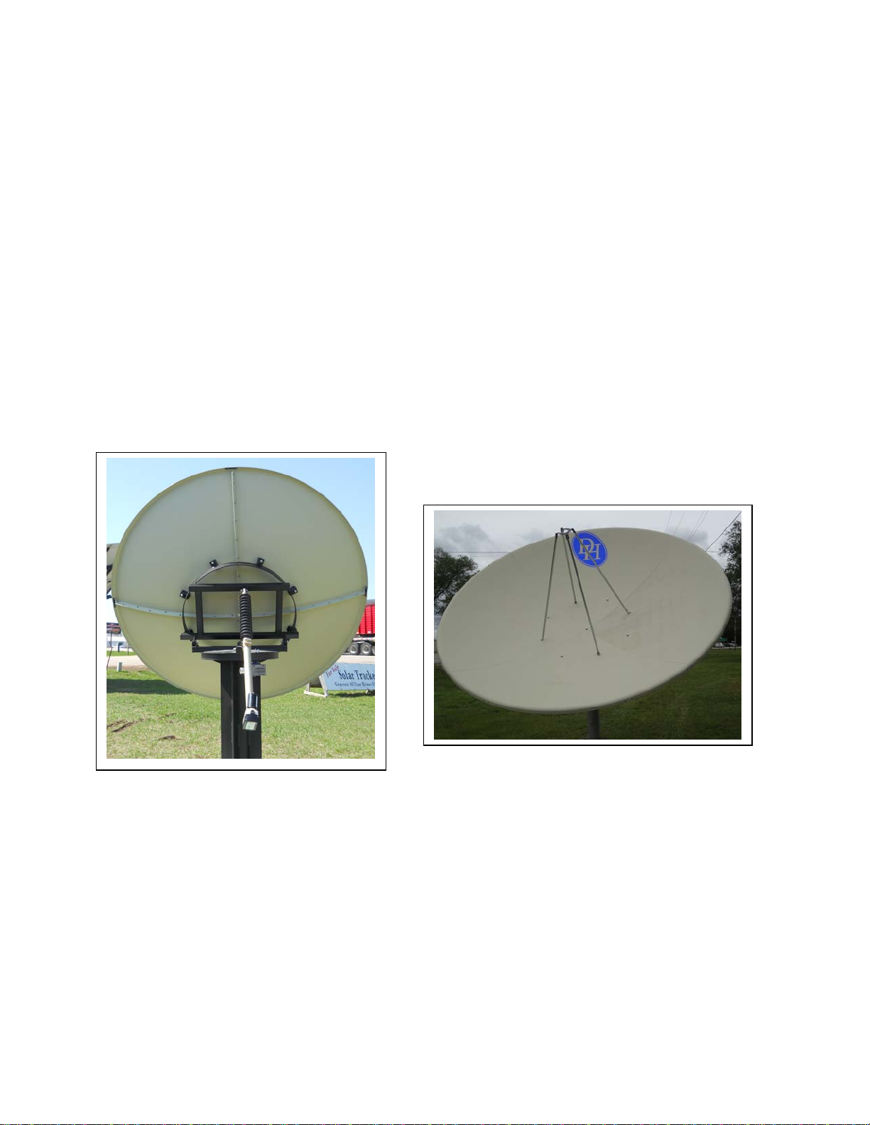
Final Inspection of the Antenna
After the assembly is complete, we recommend that you visually
look at the dish for FOUR things. 1. Make sure that both edges
are symmetrical. To accomplish this you should stand approx.
3M(10ft) away from the side of the dish. Eye ball the two edges to
confirm that they are even. This will confirm your dish is in
perfect shape. 2. Check to make sure that your feed is set to the
right focal distance. 3. Check that the feed is pointed precisely to
the center of the dish. 4. Look at all the nuts & bolts to confirm
that they are tight. After this final inspection you should be able to
install all your electronics and complete the wiring.
Technical Service: 1-608-326-8406
M-F 7:30AM to 5PM CST
www.dhsatellite.com
PAGE 12

MISSING PARTS WARRANTY
You have obtained one of the best antennas on the market today!
We hope that you will be happy with your new DH Antenna.
To better acquaint you with our system, we ask that you read the
instruction manual and verify that all of the equipment has been
supplied in your shipment. Please check the hardware as well as the
parts list and compare to what you have received. It is our policy to
make every effort to assure you that you have received all parts
necessary to make this a pleasant experience.
While checking over your parts it is possible to find that you are
missing pieces that are necessary to complete the installation. You
will find below our shipping policy and charges if any.
Notify Factory within 5 days ARO (Delivery): Red / no charge
Notify Factory 5 to 30 days ARO: Regular / no charge
Notify Factory 31 days ARO: Your cost for parts and shipping.
Please note we are only able to ship out from our location if notified by 12:00
PM CST. Calls received after this time will ship the following business day.
International shipping will need to be discussed prior to shipping.
Call us M-F 7:30 am to 5 pm 608-326-8406
PHONE: 1 (608) 326-8406
FAX: 1 (608) 326-4233
EMAIL: [email protected]
Size of antenna: _________________ Date: ______________________
Feedhorn make: _________________ Model: ______________________
LNB Make: _____________________ Model: ______________________
Please make notes below to help in future years with replacement needs.
Table of contents
Popular Antenna manuals by other brands

Channel Master
Channel Master 2016 installation instructions

Deger
Deger D25H Assembly and operating manual

HUSTLER
HUSTLER 6-BTV installation instructions

Trantec
Trantec S4.5 Series operating instructions

Cisco
Cisco Aironet AIR-ANT2568VG-N quick start guide

PRO.SIS.TEL.
PRO.SIS.TEL. PST-DDR5 Assembly instructions


 owner's manual")
VideoComm Technologies
VideoComm Technologies EAT-002 (PARA-5829) owner's manual

RCA
RCA ANT1650 - Flat Digital Amplified Indoor TV... user guide

M2 Antenna Systems
M2 Antenna Systems 403CP20 Assembly manual

Hama
Hama 121703 operating instructions

RF Elements
RF Elements UltraDish TP 400 user guide

Shure
Shure PA411 quick start guide