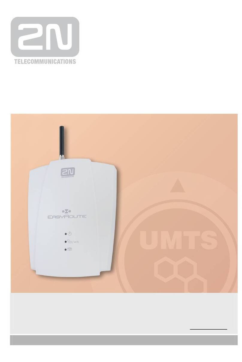
DH electronics DHCON DRC Compact User manual

User manual DRC Compact
DH electronics GmbH
R01
USM_DRC Compact-EN.docx
Page 3 / 28
Dear customer,
We are enthusiastic about technology –and have been for more than 25 years. It is our motivation to pave the
way for the digital future with our solutions. It is our spirit of discovery that drives us to realize our vision of the
future, thinking outside of the box.
We see ourselves as digital heroes who will find an individual solution for your problem together with you –also
with this product.
Thank you for choosing us and thus a product containing innovative solutions down to the finest detail. So that
you can use our product continuously and without problems, please read the user manual carefully and keep it
for future consultation.
Should you still have a problem someday, please contact us.
We are here for you and happy to help.
We hope you enjoy using this product.
Your Digital Heroes.
Premliminary

User manual DRC Compact
DH electronics GmbH
R01
USM_DRC Compact-EN.docx
Page 4 / 28
Contents
1 General product information ......................................................................................................................................7
1.1 Product details ................................................................................................................................................7
1.2 Scope of delivery..............................................................................................................................................7
1.3 Manufacturer and customer service address ...............................................................................................7
2Product description ................................................................................................................................................8
2.1 Overview...........................................................................................................................................................9
2.2 Technical specifications..................................................................................................................................9
2.2.1 Short description .....................................................................................................................................9
2.2.2 Detailed information ..............................................................................................................................10
3Safety information ................................................................................................................................................11
3.1 Graphic symbols for safety-related information .........................................................................................11
3.2 Activities according to user groups ..............................................................................................................11
3.3 Intended use ..................................................................................................................................................11
3.4 User group .....................................................................................................................................................12
3.5 Danger............................................................................................................................................................12
3.6 Special precautionary measures..................................................................................................................12
4Prepare the use of the product............................................................................................................................12
4.1 Transport and storage ..................................................................................................................................12
4.2 Disposal of product and packaging material ...............................................................................................12
4.3 Preparation of the installation......................................................................................................................13
4.4 Setup ..............................................................................................................................................................14
5Operation...............................................................................................................................................................14
5.1 Interfaces .......................................................................................................................................................14
5.1.1 Power supply..........................................................................................................................................14
5.1.2 RS485-1 ..................................................................................................................................................15
5.1.3 RS485-2 ..................................................................................................................................................15
5.1.4 RS232......................................................................................................................................................15
Premliminary

User manual DRC Compact
DH electronics GmbH
R01
USM_DRC Compact-EN.docx
Page 5 / 28
5.1.5 CAN.........................................................................................................................................................15
5.1.6 Gbit Ethernet ..........................................................................................................................................16
5.1.7 100 Mbit Ethernet ..................................................................................................................................16
5.1.8 USB Host ................................................................................................................................................17
5.1.9 Micro SD card socket.............................................................................................................................17
5.1.10 WiFi/BT ...................................................................................................................................................17
5.1.11 Status LEDs............................................................................................................................................18
5.1.12 Debug Interface .....................................................................................................................................18
5.2 Normal mode.................................................................................................................................................20
5.3 Malfunction ....................................................................................................................................................20
6Software documentation......................................................................................................................................21
6.1 System architecture......................................................................................................................................21
6.1.1 Boot loader U-Boot................................................................................................................................21
6.1.2 Linux Kernel...........................................................................................................................................21
6.1.3 Linux root file system ............................................................................................................................21
6.2 Linux boot process ........................................................................................................................................22
6.2.1 Boot loader.............................................................................................................................................22
6.2.2 Kernel .....................................................................................................................................................22
6.2.3 Root file system .....................................................................................................................................22
6.3 Device access and login ................................................................................................................................23
6.3.1 Console via Debug Interface .................................................................................................................23
6.3.2 Console via Ethernet..............................................................................................................................23
6.3.3 Web interface .........................................................................................................................................24
6.4 Updates ..........................................................................................................................................................24
6.5 Interfaces .......................................................................................................................................................24
6.5.1 RS485-1 ..................................................................................................................................................24
6.5.2 RS485-2 ..................................................................................................................................................24
6.5.3 RS232......................................................................................................................................................24
Premliminary

User manual DRC Compact
DH electronics GmbH
R01
USM_DRC Compact-EN.docx
Page 6 / 28
6.5.4 CAN.........................................................................................................................................................25
6.5.5 USB Host ................................................................................................................................................25
6.5.6 Status LEDs............................................................................................................................................25
6.5.7 WiFi .........................................................................................................................................................26
6.6 Implementing applications of your own .......................................................................................................26
7Maintenance .........................................................................................................................................................26
8Decommissioning, disassembly, disposal ..........................................................................................................27
9Order information.................................................................................................................................................28
10 Customer-specific changes .................................................................................................................................28
Premliminary

User manual DRC Compact
DH electronics GmbH
R01
USM_DRC Compact-EN.docx
Page 7 / 28
1 General product information
1.1 Product details
With the DRC Compact, you have chosen a product of the DHCON series. Our DHCON products are optimized for
smart home and building as well as Industry 4.0 and IoT applications. The DHCON DRC Compact is a universally
usable computer for control and connectivity tasks and is characterized by highest flexibility combined with low
energy consumption and an availability of at least ten years.
To guarantee a long-term, error-free service life, this manual has to be read before use and be at hand for fu-
ture consultation. You can find further useful information, documents, and software on
https://www.dh-electronics.com/en/.
Product name
DHCON DRC Compact
Product revision
R01
Product version
DH standard
Manufacturer
DH electronics GmbH
1.2 Scope of delivery
The following listing gives an overview of the components included in the delivery.
▪Short instructions
▪DIN rail controller DRC Compact
1.3 Manufacturer and customer service address
We do our best to provide you with all necessary information about our products. Should you however not be able
to solve a problem with the user manual and the documents on our website, we are happy to help. Please feel
free to contact one of our employees.
▪Via our website: https://www.dh-electronics.com/en/contact-form
▪Via e-mail: [email protected]m
▪Via phone: +49 8662 4882 0
▪Via mail: DH electronics GmbH, Am Anger 8, 83346 Bergen, Germany
Premliminary

User manual DRC Compact
DH electronics GmbH
R01
USM_DRC Compact-EN.docx
Page 8 / 28
2Product description
The DHCON DRC Compact is a universally usable computer for control and connectivity tasks and can be used as
gateway, router, or soft-PLC due to its variety of industrial interfaces. Due to its compact and robust design, it fits
perfect to industrial surroundings. The DRC Compact controller differs from other available devices due to two
special features:
▪Modular communication interface extensions
It is possible to choose between the second RS485 interface or RS232 interface or CAN.
Depending on the chosen configuration the board has one of the three interfaces above available.
▪Optional WiFi/BT connectivity
A configuration of the DRC Compact with WiFi/BT connectivity is also available. The device is fully certified
and supports all of the needed standards.
Premliminary

User manual DRC Compact
DH electronics GmbH
R01
USM_DRC Compact-EN.docx
Page 9 / 28
2.1 Overview
2.2 Technical specifications
2.2.1 Short description
Input voltage
10,8 to 26,4 VDC
Input current
2.5 A (max.)
Power consumption
4 W (typ.)
Operating temperature
0 bis +50 °C
Storage temperature
-20 bis +70 °C
Protection class
IP 30
Dimensions length x width x height
128 x 17,5 x 94,2 mm
Weight
120 g
1x 100 Mbit/s Ethernet
1x USB 2.0 host
3x status LEDs
RS485 isolated
microSD slot
Power supply: + 24 VDC
1x Gbit/s Ethernet
RS485 or RS232 or CAN
Premliminary

User manual DRC Compact
DH electronics GmbH
R01
USM_DRC Compact-EN.docx
Page 10 / 28
2.2.2 Detailed information
CPU
Type
DHCOR STM32MP157
Frequency
650 MHz
RTC
Yes, battery-backed CR1220 or internal capacitor
Memory
RAM
512 MB
eMMC Flash
8 GB
Mirco SD card slot
Up to 64GB
Interfaces
Ethernet
1 x 10/100 Mbit/s
1 x 10/100/1000 Mbit/s
Serial COM
1 x RS485 isolated
1 x RS485 or RS232 non-isolated
CAN
1 x up to 1 Mbit/s non-isolated
(instead of second serial interface)
USB 2.0
1 x USB Host 2.0
LEDs
3 x status LEDs
(2 x user defined)
Debug interface
Internal TTL UART
Wireless interfaces
Bluetooth
Bluetooth v4.2 (BR/EDR/BLE)
WiFi
WiFi 5 GHz & 2,4GHz IEEE 802.11a/b/g /n/ac
Antenna
Internal PCB antenna
Premliminary

User manual DRC Compact
DH electronics GmbH
R01
USM_DRC Compact-EN.docx
Page 11 / 28
3Safety information
3.1 Graphic symbols for safety-related information
Symbol
Category
Description
Mandatory sign
Ground before use
Prohibition sign
General prohibition sign
Warning sign
General warning sign
Warning sign
Warning of electric voltage
3.2 Activities according to user groups
Activity
Layperson
Trained specialists
Technical sales employee
Unpacking and setup
X
Connection and launch
X
Operation
X
Troubleshooting
X
Maintenance
X
Disassembly
X
Disposal
X
3.3 Intended use
The DHCON DRC Compact is a universally usable computer for control and connectivity tasks. The device may
only be used in indoor applications. Any deviating use is not intended and can lead to malfunctions. Information
on the secure operation and maintenance can be found in the respective chapters. Please contact us in case of
any problem that you cannot solve yourself.
Premliminary

User manual DRC Compact
DH electronics GmbH
R01
USM_DRC Compact-EN.docx
Page 12 / 28
3.4 User group
The device may only be used by trained specialists. The specialists can carry out the tasks mentioned in Chapter
3.2 independently. In case of failures and for maintenance tasks, please contact a technical sales employee.
3.5 Danger
Inappropriate use of the device can lead to damage of objects or the injury of people. Therefore, please make sure
to bear in mind the safety instructions included in the user manual and do not deviate from the recommended
measures, especially regarding commissioning and decommissioning, maintenance, or in case of failure.
3.6 Special precautionary measures
If you comply with the precautionary measures contained in the user manual and take into account warning and
safety indications, you should be able to operate the device without problems. Should you ever be under the im-
pression that a secure operation cannot be guaranteed, disconnect the device from the power supply as quickly
as possible and contact a technical sales employee.
4Prepare the use of the product
The following paragraph describes the correct approach before the actual use of the product.
4.1 Transport and storage
All products of DH electronics are delivered in professional packing. In any case, the products are protected from
vibrations; if necessary, a special ESD packaging is used. Our products may only be transported and stored in the
provided original packaging, as only then can a high product quality be guaranteed for a longer transport or stor-
age period. The scope of delivery should be controlled when the product is unpacked; afterwards, the packaging
has to be disposed appropriately. The customer is responsible for this.
4.2 Disposal of product and packaging material
Packaging material always has to be disposed appropriately by the customer. In addition, he is responsible for
disposing of the delivered product after termination of use at his own expense according to
legal regulations. The customer indemnifies DH electronics GmbH from the take-back obligation and related
third-party claims. Should the product be passed on to third parties, the customer must instruct these third
parties by contract regarding taking over the duty of disposal and reiterating this duty. Should the customer re-
frain from doing so, he is obliged to take the delivered product back after termination of use at his own expense
and to dispose of it according to legal regulations.
Premliminary

User manual DRC Compact
DH electronics GmbH
R01
USM_DRC Compact-EN.docx
Page 13 / 28
4.3 Preparation of the installation
Safety information
▪In electric systems, voltages can occur that are dangerous for people.
When live parts are touched, this can lead to an electric shock.
▪Make sure that the device is disconnected from the power supply.
▪
Do not supply the device via an alternating current network.
▪The device has to be grounded before use.
▪Do not drop the device.
▪Make sure that the ventilation slits of the housing are not covered and bear below instal-
lation instructions in mind!
▪The device must not be operated in inflammable or explosive surroundings.
Installation instructions
The device is clipped into a DIN rail by means of a clip on the bottom of the housing. For this purpose, put the
device onto the side opposite the clip and then push it down. The device may only be installed horizontally; a de-
viating installation is not permitted.
Installation on the DIN rail (rear view)
Horizontal installation position (front view)
Premliminary

User manual DRC Compact
DH electronics GmbH
R01
USM_DRC Compact-EN.docx
Page 14 / 28
4.4 Setup
The device is delivered in an operational condition. For setting up the device, proceed as described in the follow-
ing paragraph and bear in mind the safety instructions from Chapter 3.
▪Make sure that the power supply on the customer side is switched off at first.
▪Put the device into the DIN rail (see Chapter 4.3).
▪The device has to be grounded before use. For that purpose, connect X1 with the protective conductor.
For the power supply of the device, use a +12/+24 VDC power supply unit.
Do not supply the device with alternating voltage.
▪Connect the negative lead of the power supply with X1-GND.
▪Connect the positive lead of the power supply with X1-24 V.
▪Switch on the supply voltage.
▪The device will boot automatically.
5Operation
Bear in mind the safety instructions from Chapter 3 and the instructions for setup from Chapter 4.4. To guaran-
tee a secure operation, the device must only be used by trained staff according to Chapter 3.2.
5.1 Interfaces
The device contains various interfaces, which are listed and described briefly in the following.
5.1.1 Power supply
▪The device is supplied via a power supply unit with +10,8 to 26,4 VDC; for this a pin header with 3 poles is
used. A supply with alternating voltage is not permitted.
▪Input voltage is protected against polarity reversal, the input current is limited to 2,5 A.
▪The current limit is carried out by a 2,5 A fuse. Should you suspect it to have blown, please contact us im-
mediately.
Terminal
Pin
Name
Description
X1
Pin1
24 V
Input voltage
X1
Pin2
GND
Input ground
X1
Pin3
Ground connection *)
*) For a fault-free operation, the ground connection must be connected according to regulations!
Pin1
Premliminary

User manual DRC Compact
DH electronics GmbH
R01
USM_DRC Compact-EN.docx
Page 15 / 28
5.1.2 RS485-1
The RS485-1 interface is connected via a 6-pin header and is isolated (2,500 Vrms) from all other interfaces.
.
Terminal
Pin
Name
Description
X2
Pin1
RS485-1-A
Positive RS485 signal
X2
Pin2
RS485-1-B
Negative RS485 signal
X2
Pin3
GND_ISO
Isolated mass
5.1.3 RS485-2
The RS485-2 interface is –if the RS485 board configuration is in use - connected via the same 6-pin header as
the RS485-1 interface.
CAUTION: This interface is not isolated
Terminal
Pin
Name
Description
X2
Pin4
RS485-2-A
Positive RS485 signal
X2
Pin5
RS485-2-B
Negative RS485 signal
X2
Pin6
GND
mass
5.1.4 RS232
The RS232 interface is –if the RS232 board configuration is in use - connected via the same 6-pin header as the
RS485-1 interface.
CAUTION: This interface is not isolated
Terminal
Pin
Name
Description
X2
Pin4
RS232-TX
RS232 transmit signal
X2
Pin5
RS232-RX
RS232 receive signal
X2
Pin6
GND
mass
5.1.5 CAN
The CAN interface is –if the CAN board configuration is in use - connected via the same 6-pin header as the
RS485-1 interface.
CAUTION: This interface is not isolated
Pin1
Pin3
Pin3
Premliminary

User manual DRC Compact
DH electronics GmbH
R01
USM_DRC Compact-EN.docx
Page 16 / 28
5.1.6 Gbit Ethernet
The device offers the possibility to connect two separate Ethernet networks. One interface supports networks
with up to 1000 Mbit/s. In addition, transmitting and receiving lines are recognized automatically via Auto MDI-X,
so that both crossed and uncrossed patch cables can be used. The RJ45 sockets are allocated according to
Ethernet standard.
LED state:
The green LED is on when a 1Gbit connection is established.
The green LED is blinking while data transfer in a 1Gbit connection.
The orange LED is on when a 100Mbit connection is established.
The orange LED is blinking while data transfer in a 100Mbit connection.
The green and orange LED are on when a 10Mbit connection is established.
The green orange LED are blinking while data transfer in a 10Mbit connection.
5.1.7 100 Mbit Ethernet
The device offers the possibility to connect two separate Ethernet networks. One interface supports networks
with up to 100 Mbit/s. In addition, transmitting and receiving lines are recognized automatically via Auto MDI-X,
Terminal
Pin
Name
Description
X2
Pin4
CAN-H
CAN high signal
X2
Pin5
CAN-l
CAN low signal
X2
Pin6
GND
mass
Pin3
1x Gbit/s Ethernet
Premliminary

User manual DRC Compact
DH electronics GmbH
R01
USM_DRC Compact-EN.docx
Page 17 / 28
so that both crossed and uncrossed patch cables can be used. The RJ45 sockets are allocated according to Ether-
net standard and have a green LINK LED and a yellow SPEED LED. The blinking speed of the green LED stands
for the data transmission rate. The yellow LED lights up when the data transmission takes place with a network
speed of 100 Mbit/s. If the yellow LED does not light up, the network speed is 10 Mbit/s.
5.1.8 USB Host
The device has one USB 2.0 host interface.
The assignment of the socket corresponds to the USB 2.0 standard.
5.1.9 Micro SD card socket
The device is equipped with an microSD card slot.
The assignment of the socket corresponds to the micro SD card specification
5.1.10 WiFi/BT
The device offers the possibility to connect to WiFi networks and establish a Bluetooth connection.
The DRC Compact supports WiFi 5 GHz and 2,4 GHz and fulfils the standard IEEE 802.11a / b / g / n / ac.
The DRC Compact supports Bluetooth 4.2 (BR/EDR/BLE)
The device uses an internal PCB antenna for bringing up the WiFi and BT connection.
1x 100Mbit/s Ethernet
microSD slot
Premliminary

User manual DRC Compact
DH electronics GmbH
R01
USM_DRC Compact-EN.docx
Page 18 / 28
5.1.11 Status LEDs
The device has 3 status LEDs.
The green LED is on when the board is powered with the supported voltage.
The red LED is controlled via GPIO and can be configured by the customer.
The yellow LED is controlled via GPIO and can be configured by the customer.
5.1.12 Debug Interface
The DRC Compact supports an internal debug interface. If the front bezel is removed there can be find a 3 pin
header which is connected to the console of the device.
Status LEDs
Premliminary

User manual DRC Compact
DH electronics GmbH
R01
USM_DRC Compact-EN.docx
Page 19 / 28
With this interface it is possible to have access to the CPU via the console.
For the use of a terminal program (Tera Term, Putty), the following settings apply:
Baud rate: 115,200 bit/s
Data bits: 8 bit
Parity bits: none
Stop bits: 1 bit
Flow control: deactivated
Terminal
Pin
Name
Description
Debug
Pin1
TX
Console transmit
Debug
Pin2
RX
Console receive
Debug
Pin3
GND
mass
Pin1
Premliminary

User manual DRC Compact
DH electronics GmbH
R01
USM_DRC Compact-EN.docx
Page 20 / 28
5.2 Normal mode
After the wiring has been locked, the device can be connected to the input voltage.
The functionality depends on the specific programming.
5.3 Malfunction
The procedure in case of a malfunction depends on the software. A description will follow shortly.
Premliminary
Table of contents


