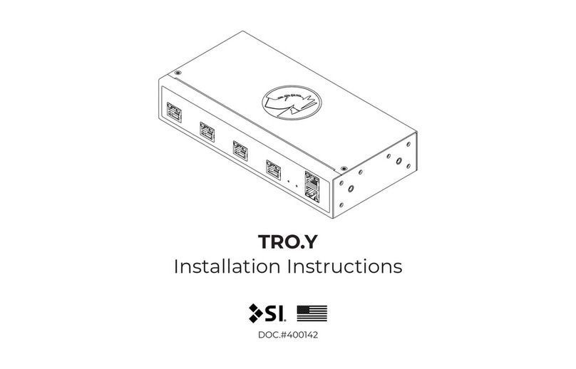
SI TRO.Y Operating instructions

DOC.#400114
TRO.Y
Programming Guide
®

2
Somfy®, UAI+™, and SDN are copyrighted and owned by Somfy Systems Inc. and are used in this
document with permission and are in full compliance with the June 2016 Somfy Trademarks, Logos
and marketing Assets Guide and Use Agreement.
All product names, logos, and brands are property of their respective owners. All company, product
and service names used in this document are for identification purposes only. Use of these names,
logos, and brands does not imply endorsement.
Copyright©2018, Control4 Corporation. All rights reserved. Control4, the Control4 logo, the 4-ball
logo, 4Store, 4Sight, Control4 My Home, Mockupancy, BakPak, Pakedge, Pakedge TruStream,
SmartWav, StealthPorts, and Triplex are registered trademarks or trademarks of Control4
Corporation or its subsidiaries in the United States and/or other countries.
2021 Copyright©US SCREEN CORPORATION

3
Table of Contents
TRO.Y Setup Procedure 5
Connection Status Types 9
Introduction 4
General Procedure Overview 4
Web browser interface etiquette 6
Home Menu 7
Dashboard 8
Firmware 10
System Settings 12
Integration Settings 13
Integration Table 16
Device Integration Table 17
485 Device Discovery 18
Device Configuration 19
485 Motor Configuration 20
RTS Receiver Configuration 23
485 Keypad Configuration 24
Keypad Comand List 26
Keypad Sequence 27
Groups 28
Super Groups 29
Broadcast Alias 30
Telnet Client Table 31
Special Groups 32
Reports 32
Programming Troubleshooting 33
Future TRO.Y Firmware releases 34

4
This guide is intended to provide step-by-step instructions to commission a TRO.Y as a central
controller for any Screen Innovations shade/screen products.
Note: If your project contains any Zigbee or RTS motors, you must complete your configuration
using the TaHoma app with your TaHoma/LinkPro Z.
Before binding any RTS products to a TaHoma or LinkPro Z, all RTS products must be fully
commissioned. Up end limits, down end limits, “my” positions, and group hand controls (Situo
remotes, DecoFlex switches, etc) must all be fully configured.
1. Connecting your TRO.Y to a PoE switch or a PoE injector
2. Discover the TRO.Y on the network
3. Create a TRO.Y account by selecting a system password
4. Configuring TRO.Y system, integration settings
5. Test and verify
www.screeninnovations.com | 512.832.6939 | Doc.#110-104a | Version 0.0.3 | 07/08/2019
Introduction
General Procedure Overview

5
TRO.Y Setup Procedure
Before starting the setup process, unbox the TRO.Y unit and connect the PoE switch or connect
to PoE injector. Verify the status LED light on TRO.Y is solid red.
1. Using a standard web browser, lets connect to TRO.Y
a. Use one of the following methods to determine TRO.Y’s IP address:
- DHCP server
If you have access to your DHCP server, locate the MAC address on the label of the
bottom of TRO.Y. All TRO.Y units MAC address will start with “70:B3:D5”
- Windows Console
Using the windows search command, type in “CMD”,
then click to open the command prompt, next type
“arp-a”. Review the list untill you find your TRO.Y’s MAC
address.
- Using universal plug-n-play
Open file explorer and click on the network icon. TRO.Y
is listed in “Other devices” in network devices.
- Now you can double click the TRO.Y icon to bring up the web browser OR
- You can right click the TRO.Y icon to bring up the TRO.Y properties including the IP
address
www.screeninnovations.com | 512.832.6939 | Doc.#110-104a | Version 0.0.3 | 07/08/2019

6
As with any web browser interface, refrain from using the standard back and forward buttons as
you can lose data that has not been saved or sent to TRO.Y. The refresh button is ok, but you can
lose data that has not been saved or sent to TRO.Y on the current page.
Web browser interface etiquette

7
Home menu has 5 selections:
- Dashboard – This is an information only page that shows
your current Wireless, Telnet Server, and Telnet Client
statues and any configured 485 devices that may be offline
and you will need the system password to proceed to any
other pages (if setup)
- Integration Table – This selection requires a valid password and provides access to the Device,
Group, Telnet Client, and Super Group tables
- Integration Settings – This selection requires a valid password and provides access to the Telnet
server, Telnet Client, Serial Control, and Wireless Bridge configuration settings
- System Settings – This selection will allow you to create a system password, adjust and view the
TRO.Y unit IP settings and update firmware
- Reports allow you to create Integration reports and soon site files
www.screeninnovations.com | 512.832.6939 | Doc.#110-104a | Version 0.0.3 | 07/08/2019
TRO.Y Data storage
Home Menu

8
- Now use a browser and navigate to the TRO.Y IP
address found using one of the previous methods
listed on pg. 4
- If this is the 1st time, you are accessing TRO.Y no
password has been created yet. See pg. 8 on how
to setup a password. If a password has already been
created, you must enter it in order to get that into
any of the menus.
- If you have forgotten the password,
pressing the reset button once on the
TRO.Y unit will allow you to bypass the
password for 5 minutes.
Dashboard

9www.screeninnovations.com | 512.832.6939 | Doc.#110-104a | Version 0.0.3 | 07/08/2019
Connection Status Types
- Telnet Server Connection – will show the
current connection or configuration status
- Wireless Bridge Connection – will show the
current connection or configuration and
authentication status
- Telnet Client Connection – will show the
current connection or configuration status
- 485 Devices offline – show all the currently
configured 485 devices that are currently offline
- Refresh – Click this button to update the Connection status
Connection status types
Check Ethernet connection, IP and subnet address(es)
Current connection is good
Disabled in the Integration Settings Menu
Performing 485 Discovery
Connection is ok, but settings are not authenticated or are not at
the currently set IP address(es) in the integration Settings menu
Connection status

10
- TRO.Y ships from factory with firmware version 1.4
- SI recommends to always update TRO.Y to the latest firmware version
- You can find the latest version in the TRO.Y resource section under firmware at the screen
innovations support website https://support.screeninnovations.com/accessories/kratos/
- TRO.Y firmware will have an extension of ###.troy. Using the “choose file” button to browse
the location where you downloaded the file on your device. Press reset button once, until the
status LED is flashing Red. Select submit to send the firmware update to TRO.Y
- TRO.Y will acknowledge the firmware update was received and you can now perform a reboot
from the settings page, or by pressing the reset button for 10 seconds, or by removing the PoE
power and then re applying the PoE power to TRO.Y
- TRO.Y will now reboot, load the new firmware and is now ready to continue your setup
Firmware

11
- If you received a “Fail” message
in the firmware dialog box, the
firmware process failed. Check
if the status LED is still flashing
Red. If not, then press the
RESET button once to enable
the TRO.Y security bypass.
- Make sure you have pressed
the reset button on the
TRO.Y unit and that the status
LED is flashing red.
- You should receive a “Good”
message, when the firmware
has been successfully updated.
- You can click the System
RESTART button now to reboot
the unit.

12
- The System name can be changed
- The currently loaded Firmware and compiled date is
shown as well as the physical MAC address
- DHCP setting can be set to enable or disable. If
disabled, a static IP address, Subnet and Gateway
can be entered
- When finished click on the Submit button
Then restart TRO.Y from the System Restart button
- You can restart TRO.Y from this button
A pop-up window will appear to
confirm you want to restart TRO.Y
System Settings

13
- The Telnet Server Settings are used
for 3rd party control systems
- Click Enable to start Telnet Server
session
- Select Telnet port (default is 23)
- Select User Name and Password
- Click submit when your configuration is
complete
- The Telnet Client Settings which are typically used for 3rd party keypads
- Click Enable to start Telnet Client session
- Select IP address and TCP port
- Set User Name and Password
- Click submit when your configuration is
complete
- Once your Telnet sessions are configured,
you must use the Restart button to
Reboot TRO.Y
Integration Settings

14
- Baud Rate can be adjusted from
4800-57600
- Parity can be Odd, Even or None
- Stop bits can be 1 or 2
- Click on Submit when configuration is
complete
Note: The colors above are from 568B, the
serial port data output (WHT/BLUE) is the
transmit (TX) from TRO.Y. The serial port data
input (GRN) is the receive (RX) from TRO.Y.
The labels from above are from EIA561.
- The Serial port Settings are used for 3rd party control systems
- Serial port and Telnet server settings are
mutually exclusive, so you can only use
one at a time
- Enable/Disable Serial port

15
- The Wireless Bridge Settings are used for
communication between TRO.Y and
Zigbee Mesh Controllers
- Enter the IP address of your Wireless
Bridge. If your gateway cannot use
static IP’s then you must create an IP lease
in your router/DHCP server
- Link ProZ and TaHoma both use port
44100 (Smarthings, and Echo hubs are not
supported by SI)
- The Wireless Bridge Settings in TRO.Y
must be set up before you activate the 3rd
party integration inside your TaHoma app.
TRO.Y has the following wireless modes:
- Disabled
- Enabled, but not authenticated/or no link
- Enabled and Authenticated
Screenshot from TaHoma app

16
- The Aggregate Integration table contains
all of the devices in your system including
motors, keypads, groups and RTS receivers
- Some devices in this table can be
configured while others may only be
shown for information purposes
- The data in this table is not yet stored in
TRO.Y, in order to save this data you must
click on the “commit integration table
button”
- You can click to configure devices on this
page, and use the wink command to
identify motors
- When you commit this table, the data is sent and stored in TRO.Y and table will turn green
- In the future release you can also save this data in a Site File
Integration Table

17
- Clicking the Device table button, will
bring you the device Integration Table
- In this table, you can create, edit, import
and delete motors, Keypads, RTS
Receivers, or Functional Zigbee Edge
Routers (on/off)
- To discover 485 motors, keypads and RTS receivers click on the 485 Discovery button
- To discover wireless devices, click on the “Import Wireless Devices and Groups” button
- You can also create any motor, keypad, RTS device by clicking on the “ Create device” button
- When you are done adding devices you can accept them (Send to Aggregate Table) or
validate them (run Design check), or erase them
- To create a Device, click on Create
Device button
- Optionally a label can be made to
help identify this device in a large
system
- Integration ID’s are auto generated,
and optionally can be edited
- If known the Native IDs can be entered in the Native ID field
- Select 485 or Wireless Communications for created device
- Select the type of device to create (Motor, Keypad, RTS receiver, Zigbee Functional Edge
Router)
- When you are done adding devices you can accept them (Send to Aggregate Table) or
validate them (run Design check), or erase them
Device Integration Table

18
- Clicking on the 485 Discovery button will bring you
to the Device Discovery menu.
- Before you click Start Discovery button, ensure you
have your 485 devices connected to one or more of
the 485 BUS OUT ports on TRO.Y
- Press Start to begin 485 Discovery
- 485 Devices will start populating in the table, this can take
some time depending on how many devices you have
- When finished click on the Pause button to stop the current discovery (clicking the Back button
also pauses the discovery)
- Click on the Clear button to erase the table of devices
- Clicking on the “Import Discovered Devices” button will send all discovered devices to the
Device Integration table
- When finished click the Back button to return to Device Integration table
- For your convenience, clicking on the
“Import 485 device” button will import
devices from the Discovery table (this
button serves the same function as
the Import Discovered Devices button
on the Discovery menu)
- To import Zigbee or RTS motors
you can click on “Import Wireless
Devices and Groups” button
(depending on size of Zigbee network, this import can take up to a min. to fully load)
- When you are done creating or importing devices you can accept them (Send to Aggregate
Table) or validate them (run Design check), or erase them
485 Device Discovery

19
- Clicking on a “Config” button will
bring up the Device Configuration
page
- Clicking on the “Wink” button will
send a momentary up and down
movement to the motor.
- Zigbee and RTS motors need to be
configured in the TaHoma app before they will be listed in this aggregate table
Device Configuration

20
- Enter the properties menu by clicking the “Properties”
button
- In the properties the Node Id, firmware (if available),
serial number and motor type are displayed
- The label, motor rotation, and speeds can be
adjusted
- Clicking the “Submit” button sends any changes
to the motor
- Click on another menu button or if you are done,
click the “Back” button to take you back to the
Aggregate Integration table
485 Motor Configuration
- Clicking on the motor “Config” button will
bring you to the Device Configuration menu.
- 485 motor confirguration has 4 menus,
properties, limits, presets, groups
- Motor movement controls allow you to adjust
the motor (@=stop)
- Click “Refresh” button to see current position
Other manuals for TRO.Y
1
Table of contents
Other SI Gateway manuals