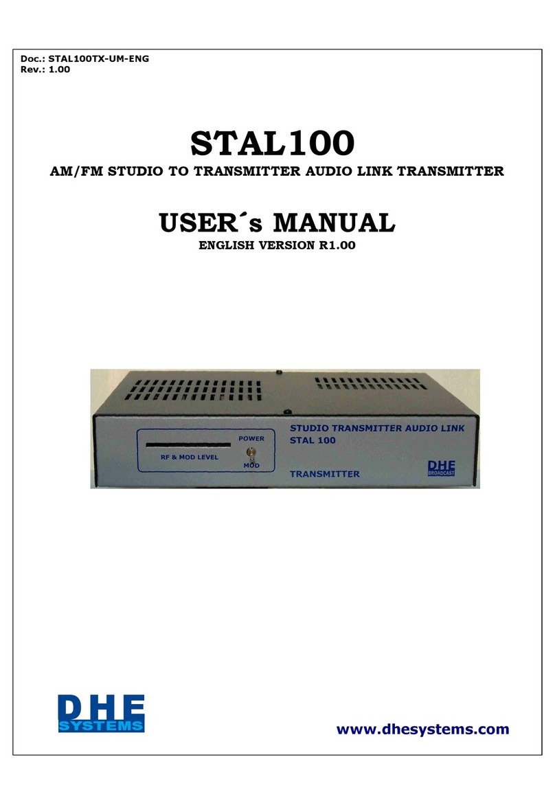
DHE SYSTEMS STAL1000 User manual

Doc.: STAL100TX-UM-ENG
Rev.: 1.20
STAL1000
AM/FM STUDIO TO TRANSMITTER AUDIO LINK TRANSMITTER
USER´s MANUAL
ENGLISH VERSION R1.20
www.
dhesystems
.co
m
H
D
E
SYSTEMS

USER´s MANUAL NDEX RECE VER STAL1000
Doc.: STAL1000TX- UM -ENG
Rev.: 1.20
SECT ON CONTENS
1 REV S ONS
2 ABOUT TH S MANUAL
3 WARRANTY
4 UNPACK NG
5 NSTALAT ON
6 MA NTENANCE AND SERV C NG
7 GENERAL DESCR PT ON
8 TECHN CAL SPEC F CAT ONS
9 PROGRAMM NG COMMANDS

USER´s MANUAL REV S ONS RECE VER STAL1000
Doc.: STAL1000TX-UMR-ENG
Rev.: 1.20
SECT ON 1
REV S ON
MODEL SOFTWARE DOC. REV. REPLACE TO REPLACED BY DATE
STAL1000-TX 1.00 1.00 ---------- 1.20 10/02/13
STAL1000-TX 1.20 1.20 1.00 ---------- 15/06/14

ABOUT TH S MANUAL
Doc: STAL1000TX-ATM
Rev.: 1.20
This manual has been written with the purpose o providing a general explanation, serve as re erence and
support and it shall be used only by quali ied technical personnel.
It should be noted that this equipment uses widely sur ace mount technology (SMT) components , so at certain
times and to a severe ault there is no chance to repair the module/s and will be necessary to replace it/s.
Because in this equipment there are currents and voltages dangerous or humans never operates it connected to
the mains AC line without the actory coverage removed.
Never open the equipment, remove parts or components without irst turning it o and disconnect it rom the
mains AC line.
I you have to service with the equipment in operation, you must ollow care ully the protection rules
and electrical insulation or the intervening personnel.
This equipment contains electrical and / or electronic components whose manipulation can be harm ul to the
human being in case o not proceeding adequately, there ore the corresponding precautions should be taken.
SECT ON 2

WARRANTY
Doc.: STAL1000TX-WAR
Rev.: 1.20
DHE SYSTEMS warrants this equipment for a period of one (1) year from the date of delivery
against defects in manufacturing workmanship and / or defective material at no extra
charge. To comply with this warranty the equipment should be sent to the factory in
its original and complete packaging, including all accessories with was dispatched in the
same, with transportation costs, insurance, duties, taxes and all other additional costs
generated in the process of shipment to the factory and subsequent return to the client, paid
advance and according to the following conditions:
1-This warranty does not cover damage that could possibly occur during transport to the
customer, not from it to the factory, where the equipment sent for repair, adding options,
packaging, etc.
2-This guarantee does not apply if in the opinion of DHE SYSTEMS is determined that the
defect in the equipment is a result of improper handling, installation and operation outside
the recommendations provided by DHE SYSTEMS, use the equipment for other applications
for which was designed, intervention of technical personnel not expressly authorized by DHE
SYSTEMS, and / or not qualified enough, damage power conditions outside the
specifications, environmental conditions and / or adverse, extreme and unpredictable
weather, electric shock on the line power, signal, data, control or antenna.
3-This warranty does not cover damages that may occur in radio frequency power
transistors, power supply, connectors, keyboards and displays due to improper handling or
as a result of the conditions expressed in P2.
4- n if necessary replace materials that are not manufactured by DHE SYSTEMS replenishing
them at no additional cost to the customer will be subject to that obtained from the
manufacturer and / or supplier thereof. To this point the general conditions apply.
5-DHE SYSTEMS ensures equipment specifications, but is not responsible for the coverage
area that is intended to achieve with it.
6-This warranty does not cover damage that may occur directly or indirectly on other
equipment connected to, or during the use of the equipment.
7-No other warranty that is not expressed in this document will be recognized by DHE
SYSTEMS.
8-The conditions of this warranty may be modified by DHE SYSTEMS without notice or
authorization.
SECTION 3

UNPACKAG NG
Doc.: STAL1000TX-UN-EN
Rev.: 1.20
This equipment was tested, inspected and packed care ully at the actory. Check upon receipt that the packaging is
in per ect condition, and or any bumps or breaks on the packaging itsel or sa ety belts. I this happens document
it immediately upon receipt o the equipment.
Unpack the equipment and check at a glance that no damage is observed, and that the content matches the list
contained in the document "PACK NG L ST" in the box. I damage is observed ask or an inspection o the
carrier, and immediately contact the dealer or distributor where you made the purchase.
I the content does not match that listed contained in the document "PACK NG L ST" immediately contact the
dealer or distributor where you made the purchase.
CAUT ON: Keep the packaging material with which was sent equipment or subsequent shipment to actory i
necessary within or outside the warranty period, since otherwise a charge or replacement o the original
packaging will be charged.
SECT ON 4

Doc: STAL1000TX- WN-ENG
Rev: 1.20
WARN NG
TH S EQU PMENT HAS A FACTORY SUPPL ED POWER AC CORD W TH
GROUNDED P N. BEFORE TO CONNECT THE UN T TO THE AC POWER
L NE, CHECK FOR A GOOD AC NSTALLAT ON GROUND. F THE AC
NSTALLAT ON HAS A POOR GROUND THE OPERAT ON OF THE UN T
W LL BE NOT SURE FOR THE PERSONNEL. NEVER USSES AC ADAPTORS
W THOUT GROUND TERM NALS.
NEVER REPLACE THE RF, S GNAL OR CONTROL CONNECTORS FOR
D FFERENTS TYPES THAN THE OR G NALS SUPPL ED W TH THE
EQU PMENT.
NEVER MAKE D RECT CONNECT ONS FROM THE NTER OR OF THE
EQU PMENT.
ANY OF THE PREV OUS S TUAT ONS W LL REVOKE THE FACTORY
WARRANTY.
TH S EQU PMENT HAS MONO AND MPX NPUTS COUPLED N
CONT NUOUS CURRENT, SO T SHOULD ENSURE THAT THE EQU PMENT
CONNECTED TO T DOES NOT PRESENT LEVELS OF CONT NUOUS
VOLTAGE N TS OUTPUTS, OTHERW SE DAMAGE TO THE EQU PMENT
MAY OCCUR.
TH S EQU PMENT COMES PROV DED W TH FOUR PLAST C LEGS
LOCATED N THE BOTTOM FOR WHEN TH S S USED MOUNTED N
SHELF. F THESE D FF CULTY YOUR NSTALLAT ON N NORMAL ZED
RACK CAN BE REMOVED REMOV NG THE THREADED SCREWS TO THE
GAB NTE W TH THOSE THAT ARE SUBJECT.
SECT ON 5

Doc.: STAL1000TX- NS
Rev.: 1.20
NSTALALAT ON
Be ore proceeding with the connection o the equipment to the electrical network, veri y that the voltage o the
same is within the operation range o the equipment, and that it is o . I you are not sure that the network power
is clean, stable and ree o transients, a stabilizer and transient suppressor o at least 100 W o power should be
used.
Install the equipment in a clean, ventilated place and in which the temperature is within the range o operation o
the equipment.
Connect the antenna cable to the "N" connector located on the rear panel. Use or this operation coaxial cable with
50 Ohms impedance and low losses. Never use coaxial cable type RG58 or this unction. I the necessary length o
the cable is reduced, a low cost cable can be used, such as RG213, otherwise use Cel lex o ½ "or similar.
Veri y be ore putting the equipment in transmission, that the load to which it is going to connect presents an
adequate adaptation in such a way that the ROE is within the parameters accepted by it, and i possible veri y it
using other equipment. I you do not have this possibility and i you do not know the conditions o the load to
which the equipment is to be connected, program it be orehand in requency and power using an arti icial load,
and set the power output to 3W, to reduce the risk o damage when connecting it to the load that will be de initely
used.
Connect the program inputs according to the use that will be given to the equipment, using shielded cable or the
Mono input, and 75 Ohms coaxial cable or the Mpx input.
Turn on the device and veri y that a ter a ew seconds the display shows the welcome message.
Wait until the "PLL" led lights up indicating that the synthesizer is engaged.
From this moment the equipment is ready to be used. Re er to the User Manual to obtain a detailed description o
the operation, commands and unctions available through the Multi unction Panel.
CONNECTORS P NS ASS GMENTS
BALANCED MONO NTPUT
Pin 1- Ground
Pin 2- Positive balanced intput
Pin 3- Negative balanced intput
UNBALANCED MONO NTPUT
Pin 1- Ground
Pin 2- Unbalanced intput
Pin 3- Ground
SECT ON 5/1

SERV C NG AND MA TENANCE FOR THE STAL1000 TRANM TTER
Doc.: STAL1000TX-MAN-ENG
Rev.: 1.20
This equipment has been designed and built to operate in a continuous cycle without degradation o its
parameters, however it may require maintenance and / or repair in certain occasions, or in case o ailures caused
by abnormal situations in the electrical network, electric discharges on the power lines , signal, data, control and
antenna.
I it is necessary to replace the power use (s), always do so or others o the same current.
The only recommended maintenance is the periodic cleaning o the ventilation inlets to allow the passage o clean
air and in the volume necessary to ensure the correct cooling o the equipment.
The printed circuit modules can also be cleaned by blowing clean, dry pressure air over them. Never use solvents
or this operation as this can cause severe damage to the components or permanently disable the plate.
The above cleaning operations are recommended when the equipment operates in environments with a high dust
content in the air.
To carry out any type o maintenance and / or repair operation, the power supply must be disconnected rom the
power supply be ore proceeding to remove the coverings and shields.
HANDL NG OF THE MODULES
The modules in this equipment are mostly provided with connectors, so to remove them it is only necessary to
disconnect these connectors and remove the set screw / ixing washer.
Special care must be taken when reinstalling a module, to veri y that the connectors are connected in the same
place and position in which they were originally, otherwise damage may occur to them and / or to other parts o
the equipment.
HANDL NG OF COMPONENTS
This equipment uses SMD sur ace mount technology or smaller components such as resistors, capacitors, diodes,
low and medium power transistors and integrated circuits. To remove them always use adequate desoldering tools.
Special care should be taken not to damage the printed circuit board or the metallic holes when removing a
component, since there is a risk that the module will be permanently disabled.
REPLACEMENT OF MODULES
In certain circumstances and in the event o damage caused by non-speci ied power conditions, adverse
environmental conditions and / or extreme, unpredictable, electric discharges on the power supply, signal, data,
control or antenna, it will be necessary to completely replace the / Damaged modules, pej, power supplies, RF
input stages, CPU board, etc.

SECTION 6

GENERAL DESCR PT ON OF THE STAL1000 TRANSM TTER
Doc.: STAL1000TX-GD-ENG
Rev.: 1.20
The AM / FM STAL1000 link transmitter is a state-o -the-art equipment, the result o the experience accumulated
over the years in the manu acture o broadcasting and communications equipment.
Designed and built to comply with international standards incorporates synthesized technology, programming and
measurement o parameters in an agile and simple way through the multi unction panel with keyboard and
display, and operates within the band or which it is programmed without adjustments.
The synthesizer is o the direct synthesis type and uses a modulator o exclusive design that allows it to operate
within the whole band with very low distortion and dispersion in the modulation index.
It has detection o the state o the PLL that prevents the transmitter rom delivering power until the synthesizer
has inished stabilizing.
Indication o the status o the PLL, the transmitter and the mode o operation using LEDs on the ront.
It has Monaural and Mpx options, and input or auxiliary service.
The input in Mono mode is balanced / unbalanced with XLR connector, in Mpx mode and or unbalanced auxiliary
service with BNC connector.
The RF power ampli ier is o the broadband type built with printed lines and LDMOS transistor and convection
ventilation.
Switching power supply rom 100 to 130 Vac and 180 to 240 Vac allows it to operate over the voltage range
without degradation o the parameters.
Its modular construction, made mostly with connectors to link the di erent modules, makes it very easy to service
it.
The electrical shielding available allows the installation o the equipment directly at the site where the main
transmitter is located, since this shield protects it rom electrical radiation coming rom outside.
The multi unction panel allows programming and measuring in an agile and simple way the di erent parameters o
the equipment, with access code to prevent the entry o unauthorized personnel to critical unctions. The
in ormation presented on the display can be programmed to be viewed in Spanish or English.
All the parameters o the equipment are saved in memory once they are set, so they are retained when the
equipment is turned o , and reset when turned on again.
SECT ON 7

TECHN CAL SPEC F CAT ONS FOR THE STAL1000- TRANSM TTER - R1.20
Doc.: STAL1000TX-SPE-ENG
Rev.: 1.20
Synthesis type Direct FM.
Frequency precission ±2.5 ppm a ter de 30 minutes.
Temperatura range 0 a 45 °C.
Frequency stability ±2.5 ppm, 0°C to +45 °C.
Frequency programming From keyboard in 25 Khz steps, protected by key.
Frequency range 200/520 Mhz (in 25 Mhz requency steps).
900/920 Mhz, 920/940 Mhz, 940/960, 960/980 Mhz.
Maximum deviation ± 75 Khz @ 100 % modulation.
Signal to noise ratio mono
Signal to noise ratio mpx
> 65 dB, @ 1Khz @ ± 75 Khz, w/ ilter de 15 Khz.
> 60 dB, @ 1Khz @ ± 75 Khz, w/ ilter de 80 Khz.
Maximum available power 200/520 Mhz: 15 or 50 Watts, adjustable.
900/980 Mhz: 10 Watts, adjustable.
Out o band emissions Better than – 60 dB.
Maximum re lected power admissible 1.5 W or 15 W option, 3 W or 50 W option.
Inputs Mono : 600 Ohms ± 5% balanced, unbalanced, XLR.
Mpx : 2 K ± 5% unbalanced, BNC.
Aux : 10 K ± 5% unbalanced, BNC.
Input level Mono : -10 to + 10 dBm (0.25 a 2.5 Ve ) @ ± 75 Khz.
Mpx : -10 to + 10 dBm (0.45 a 4.5 Ve ) @ ± 75 Khz.
Aux : 3.5 Ve @ ± 7.5 Khz.
Frequency response Mono : ± 0.2 dB, rom 30 to 15000 Hz r
re erred to the standard
preenphasis curve.
Mpx : ± 0.2 dB, 30 Hz to 100 Khz.
Aux : ± 0.5 dB, 30 Hz to 100 Khz.
Distortion Mono : < 0.1 %, @ 1 Khz, @ ± 75 Khz.
Mpx : < 0.1 %, @ 1 Khz, @ ± 75 Khz.
Aux : < 0.2 % @ 7,5 Khz.
Modulation latness ± 0.4 dB, @ 1Khz, @ ± 75 Khz, rom lower and upper requency
range with respect to the center o band.
Preenphasis 0, 25, 50 o 75 useg selectable.
Indicactions Transmitter status, PLL status, by leds.
Meditions Forward and re lected output power, modulation level, input
attenuator level, main power supply voltage.
Keyboard programming Frecuency, operation mode, modulation level, output power, display
language, user key.
Antenna 50 Ohms unbalanced. Connector “N” emale.
Power request 100/130 Vca – 180/240 Vca - 47/63 Hz, switching power suppy,
jumper select.
Dimensions Height: 2U - Wide: 430 mm - Deep: 330 mm.
Power drain 15W option : 45 W
50W option : 110 W
Weight 15W option: 7.5 Kg
50W option: 9.0 Kg
SPEC F CAT ONS MAY CHANGE W THOUT PREV OUS NOT CE
SECT ON 8

COMMANDS AND PROGRAMM NG NDEX FOR THE
STAL1000 TRANSM TTER
Doc.: STAL1000TX-CP -ENG
Rev.: 1.20
SECC ON CONTENS
9/ 1 ACCESS FUNCT ONS AND COMMANDS DECR PT ONS
9/ 2 USER MODE
9/10 MULT FUNCT ON
9/15 N T AL SETT NGS
9/21 TRANSM TTER NFO
9/23 USER MODE HELP
9/24 COMMANDS QU CK REFERENCE
SECT ON 9

DHE BROADCAST
STAL
100
0
USUER MODE
FUNC(0:HELP):
_
COMMANDS
DESCR PT ON
Doc.: STAL1000TX-COM-ENG
Rev.: R1.20
1-ACCESS FROM KEYBOARD
Power on. Alter a ew seconds the display will show this message:
The STAL1000 Transmitter is ready to receive commands rom the keyboard.
Below is the list o the keys assigned unctions or the keyboard:
KEY FUNCT ON
E Enter, is the irst key to be pressed to access the menu and to exit rom the previous sub menus.
C Correct, let to correct errors in the character typed.
↑
↑↑
↑↓
↓↓
↓ Increment and decrement value o the selected and available unction.
0 a 9 Numeric keys.
The main menu have our sub menus. You can select one o them pressing:
E: USER MODE
E+1: USER PROGRAMM NG
E+2: MULT FUNT ON METER
E+3: START SETT NGS
E+4: EQU PMENT NFO
E+0: USER PROGRAMM NG HELP
USER MODE
1.1-Press "E”
The display show:
Pressing "E" again to exit to P1.
SECT ON 9/1

2-USER PROGRAMM NG
Sequence: E + 1
The display shows:
The available options are:
E : Exit to P1.1
E+1+1: Transmitter enabled/disabled
E+1+2: Frequency setting
E+1+3: Access to memories
E+1+4: Input attenuator & modulation level
E+1+5: Output power setting
E+1+0: Help or “User programming mode”
SECT ON 9/2
USER PROG
FUNC(0:HELP):

2.1-Transmitter enable / disable
Sequence: E + 1 +1
It is a cyclic operation key, i the transmitter is disabled, it activates it and vice versa.
I the transmitter is disabled, the display shows:
The "TX" LED on the MEASUR NG AND CONTROL PANEL will light up.
At the end o the operation the panel returns to P2.
I the transmitter is enabled, the display shows or 2 seconds:
At the end o the operation the panel returns to P2.
CAUT ON: The equipment retains in non volatile memory the last state in which the function
was found to activate / deactivate the transmitter when switching it off intentionally or
accidentally, pej. before a power cut. n this way, if the transmitter was activated, when it is
turned on again or the power is restored, it will start up in transmission. Special care must be
taken when turning on the equipment that is connected to the load, if the status of the
activation / deactivation of the transmitter was not known before turning it off, otherwise the
destruction of the power stage of the transmitter may occur. RF.
SECT ON 9/3
TRANS: ENA WA T
TRANS:D S

2.2-Frequency settings
Sequence: E + 1 + 2
The display shows:
I you do not want to change the requency, press "E" to return to P2.
Enter the current our digit user key. By de ault, the key is 1234. The typed key is not
shown, the characters are replaced by "*". The key is checked one time the our entered
digits I this is incorrect, the message "ERROR" is heard and it is returned to P1. I during the process o
typing the key you decide to exit the requency change option, press "E" to return to P2.
I the password entered is correct, the ollowing message is displayed:
I you do not want to change the requency, press "E" to return to P2.
The irst digit shown corresponds to the irst digit o the lower limit o the band.
Enter the requency in steps o 25 Khz. The accepted terminations are 00, 25, 50, 75 Khz. The digits o the
new requency are checked when entering the one corresponding to the Mhz, so in case o inding that the
requency is out o the range o operation o the equipment, the message o "ERROR" is heard, and it is
returned to P2. I during the process o typing the new requency you decide to exit the requency change
option, press "E" to return to P2.
Once the new operating requency has been entered, the display shows:
Press "1" to save the new requency, "2" to exit the option without changing it.
SECT ON 9/4
CURRENT KEY :
NEW FREQUENCY
X
STORE FRE:XXX.XXX
1:YES
2:NO:

2.3- Access to memories
Sequence: E + 1 + 3
The display shows:
Press "E" to return to P2
2.3.1-Download requencies stored in memories
Sequence: E + 1 + 3 + 1
The display shows:
I you do not want to access a memory, press "E" to return to P2.2
Enter the current our-digit user key. By de ault, the password is 1234. The key is not typed
is displayed, the characters are replaced by "*". The password is checked one at a time entered the
our digits I this is incorrect, the message "ERROR" is heard and it is returned to P1. I during
the process o typing the key is decided to leave the requency change option, press "E" to return to
P2.2
I the password entered is correct, the ollowing message is displayed:
Select the desired memory by entering the numbers rom 1 to 0. The display will show
successively the number o the memory selected and the requency stored in it, pej .:
Once you have ound the memory whose requency you want to program in the device, press "E"
The display shows:
Press “1” to store the new memory, “2” to exit without change the current memory and to return
to P1.
SECT ON 9/5
1:DOWN MEM
2:UP MEM
CURRENT KEY :
MEM :
MEM :
MEM5:233.025 MHZ
MEM :
STORE FRE: 233.025
1:
YES
2:NO:

2.3.2- Program the requencies to be stored in memory
Sequence: E + 1 + 3 +2
The display shows:
I you do not want to access a memory, press "E" to return to P2.2
Enter the current our digit user key. By de ault, the password is 1234. The key is not typed
is displayed, the characters are replaced by "*". The password is checked one at a time entered the
our digits I this is incorrect, the message "ERROR" is heard and it is returned to P1. I during
the process o typing the key is decided to leave the requency change option, press "E" to return to
P2.2
I the password entered is correct, the ollowing message is displayed:
The irst digit shown corresponds to the irst digit o the lower limit o the band.
Enter the requency in steps o 25 Khz. The accepted terminations are 00, 25, 50, 75 Khz. The digits o the
new requency are checked when entering the one corresponding to the Mhz, so in case o inding that the
requency is out o the range o operation o the equipment, the message o "ERROR" is heard, and it is
returned to P2. I during the process o typing the new requency you decide to exit the requency change
option, press "E" to return to P2.
Once the new operating requency has been entered, the display shows:
Enter the number o the memory in which you want to save the programmed requency, pej 2
I you do not want to save it in any memory, press "E" to return to P2.2
The display shows or a moment:
Then it is returned to P2.2.2
Press "E" to return to P2.2
SECT ON 9/6
CURRENT KEY :
FRE : 2
MEM5:233.025 MHZ
MEM :
MEM5:233.025 MHZ
MEM :
2

2.4-Input level attenuator & modulation level
Sequence: E + 1 + 4
The display shows:
The digital control o the input level attenuator level allows to modi y it between -10dB and +10 dB.
I "E" is pressed without changing the output level value, it is returned to P2.
The modulation level is displayed in digital and analog ormat in the orm o bars.
Under normal modulation conditions, the analog meter moves rom the minimum to the maximum o 75 Khz,
indicated by bar Nº. 13. The irst symbol “∗
∗∗
∗” indicates 110% modulation.
To modi y the modulation level, press the “↑
↑↑
↑↓
↓↓
↓” keys until the desired value is reached. Once this one is
reached, press "E".
The display will shows:
Press “1” to store the new output level, “2” to exit without change the current output level and to return
to P1.
SECT ON 9/7
MOD: 75 K AT: 6dB
∗
∗∗
∗ ∗
∗∗
∗ ∗
∗∗
∗
STORE LEVEL: 6 dB
1:YES 2:NO:
Table of contents
Other DHE SYSTEMS Transmitter manuals
Popular Transmitter manuals by other brands

Jamara
Jamara CCX Lipo 2,4 GHz 3 CH Instruction

Air Monitor
Air Monitor VELTRON II Installation, operation and maintenance manual
Rough and Ready
Rough and Ready YS-1010S operating manual

Air Monitor Corporation
Air Monitor Corporation ELECTRA-flo Installation, operation and maintenance instructions

SenseAir
SenseAir aSENSE user manual

Vislink
Vislink HDX-1100 User and technical manual
