DHR 230RCN 230 Technical manual

Navigation Lights
Signalling Lights
Searchlights
Whistles
TECHNICAL DOCUMENT
DHR 230RCN 230
Remote Controlled Searchlight
Den Haan Rotterdam
S
i
n
c
e
1
9
2
2

2Version 1.0 October 2018
Den Haan Rotterdam
(Intentionally blank page)

3Version 1.0 October 2018
Den Haan Rotterdam
Safety notes:
• Turn power off before inspection, installation or removal
• Keep combustible materials away from lamp
• Do not exceed 105% of rated voltage
• Allow lamp/fixture to cool before handling
• Do not use the searchlight if outer glass is scratched or broken
Damage due to inappropriate handling is
not covered by the warranty.
© Copyright, Den Haan Rotterdam B.V.
Version 1.0 October 2018
This document contains proprietary information that is protected by copyright.
All rights reserved.
!
4Version 1.0 October 2018
Den Haan Rotterdam
Den Haan Rotterdam is a family-owned company established in 1922. Started as a small tinsmith, it has
evolved into a globally respected producer of navigation lights, searchlights, air horns and a wide range of
nautical lamps made from copper and brass. By introducing products with advanced LED-technology, DHR
has safeguarded a visibly safe future for marine vessels in all weather conditions.
Den Haan Rotterdam manufactures halogen searchlights for over 30 years and are known for their robust-
ness, quality and reliability: key values for marine equipment. The RCN-series is the second generation of
DHR remote controlled type of searchlights introduced in 2011. This product range is very popular, because
of its compact size and its simplicity in installation and operation. The RCN-series includes various types of
light sources, such as: halogen bulbs, sealed beams and metal halide bulbs. Also the optical performance
is top-notch, thanks to the use of silverplated mirror reflectors in the 260 & 350 models.
The application of the 260- and 350-series searchlights is limitless. Mostly they are benificial for work boats,
tugs, fishing vessels, dredgers and even watch towers for land based solutions.
DEN HAAN ROTTERDAM B.V.
D.M. Den Haan
Managing Director
FOREWORD
QUALITY STANDARDS
Excellent Optics
Maintenance Friendly
Light Weight Construction
IP66 Water Ingress Protection
Remote control
LED technology

5Version 1.0 October 2018
Den Haan Rotterdam
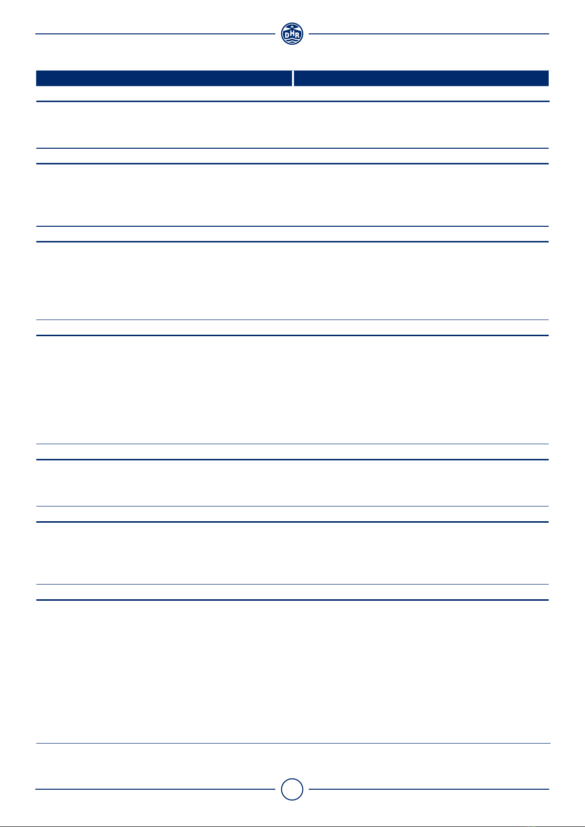
TABLE OF CONTENTS
1. Mounting instructions 6
2. Specifications 8
3. Dimensions 11
4. Photos 13
5. Wiring diagrams 14
6. Maintenance and correct use 19
7. Replacing of motor frame 20
8. Recommended spare parts 21

6Version 1.0 October 2018
Den Haan Rotterdam
1. MOUNTING INSTRUCTIONS
Mounting the panel
Place the control panel inside the wheelhouse, where it is protected against weather influences. The housing
is especially constructed to be flush mounted in an instrument cabinet according the illustration on the right.
The minimum space needed behind the panel is 110 mm. (depth)
97 ± 1 mm
97 ± 1 mm
Cut-out panel
Searchlight installation
Install the searchlight in a horizontal upright position with sufficient space around the head of the searchlight
to ensure it can move freely. The dimensions can be found on page 9.
Bolt M10x (60 + M)
Insulation sleeve
Lantern base
Insulation sleeve
Washer M10
Mounting plate Min. 5 mm
Nut M10
M
All dimensions in mm
Fasteners
• The permissible torque should be 8 Nm
• Use only A4-grade stainless steel
Caution!
Even though the housing is made of corrosion resistant materials, galvanic corrosion may still occur. To
prevent galvanic corrosion use the supplied insulation sleeves to isolate the aluminium housing from
other metal parts.
4 x Ø10
162,5
162,5
Warning!
Den Haan Rotterdam does not accept responsibility for any damage if the searchlight is in-
stalled incorrectly and/or used improperly. When in doubt consult a qualified electrical techni-
cian.
!

7Version 1.0 October 2018
Den Haan Rotterdam
Electrical installation
Install the electrical wiring according to the wiring diagrams showed on pages 11 - 14. Keep the distance
between the power supply and halogen lamp as short as possible. Long wires will increase a voltage drop
near the halogen lamp, which affects the light output.
Cable glands
ØD
Cable
• Prefered diameter D is 7 - 12 mm
• Material: Neoprene H07RN-F
Cable too tight!
This gives unwanted stress at the sealing of the
cable gland and water ingress will occur.
Include cable slack at the entering
point of the cable gland
Replacing cable gland
• Use gasket between housing
and cable gland
• Tighten firmly (6Nm) with
wrench
Remove the plug before placing the cable.
If no cable is connected, leave the plug in place!
Note
The cable glands on the searchlight prevent water ingress. Do not use (electrical) tape to cover the
cable where it enters the cable gland as this will cause water ingress. Do not use a rubber or shrink-
able cover on the cable gland to improve water tightness.

8Version 1.0 October 2018
Den Haan Rotterdam
2. SPECIFICATIONS
Control panel
Model PAN2011
Dimensions
Depth 110 mm
Width 110 mm
Weight 0,6 kg
Electrical
Voltage 24 VDC±20%
Maximum wattage 20 W
Fuse T2A
Electrical insulation class III
Housing
Front Stainless steel 316
Back Aluminium, painted black
Operating temperature 0° / + 45° C
Switches
1. BEAM ON/OFF, switches the searchlight on or off.
2. Joystick, controls the direction of the movement.
3. ON/OFF, switches the panel on or off.
Potentiometers
4. SPEED U/D, speed of the movement up and down.
5. SPEED L/R, speed of the movement left and right.
ON/OFF
BEAM ON/OFF
SPEED U/D SPEED L/R
1
3
2
4 5
9Version 1.0 October 2018
Den Haan Rotterdam
Searchlight
Model 230RCN230
Dimensions
Height 617 mm
Width 331 mm
Weight
Electrical
LED-driver 230 VAC / 75W
Motor voltage 6-13 VDC
Preferred cable type H07RN-F
Cable diameter Ø 6-12 mm
Optics
Mirror Parabolic mirror reflector Ø 230 mm
Range 775m
Adjustable Focus No
Beam angle at 50% -
Luminous intensity 600.000 cd
LED
Model CLU731
Luminous flux 8767 lm
Rated LED voltage -
Rated LED wattage -
Average life-time 30.000 h
Color temperature 5000 K
Base -
Heater
Type PTC-heater
Voltage 24VDC
Maximum wattage 70 W
Motor Unit
Tilt + 30° / - 60°
PAN 340°
Max. speed left / right approx. 34°/ sec
Max. speed up / down approx. 3,2° / sec
Housing
Material Chromated seawater resistant aluminium
Finish UV resistant powder coating - White RAL9016
Front glass Hardened front glass
Seals Silicone / Neoprene, black
Cable gland M25x1.5
Operating temperature - 25° / + 40° C
Ingress protection class IP66 c/w Membrane vent

10 Version 1.0 October 2018
Den Haan Rotterdam
11 Version 1.0 October 2018
Den Haan Rotterdam
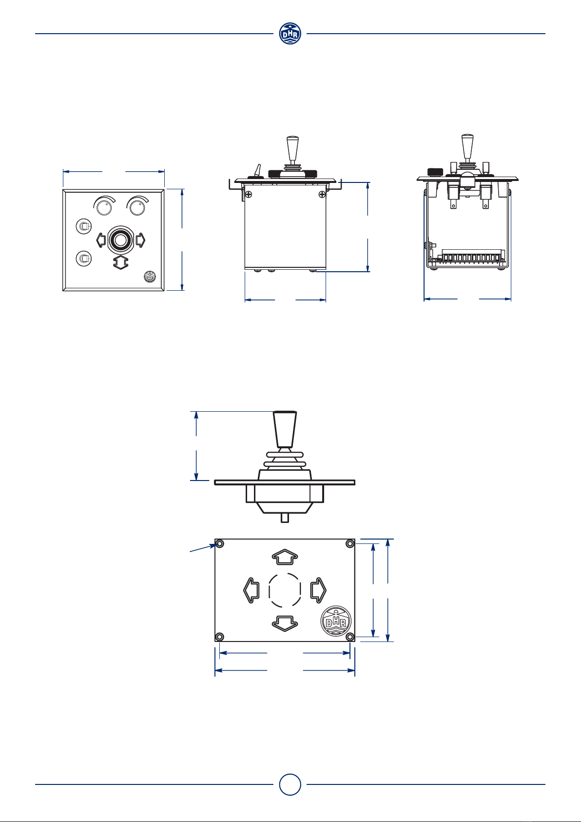
3. DIMENSIONS
All sizes are in mm.
Control Panel
Joystick
112
SPEED U/D SPEED L/R
BEAM ON/OFF
ON/OFF
94
88
98
110
110
6660
84
90
Ø3
45

12 Version 1.0 October 2018
Den Haan Rotterdam
All sizes are in mm.
Base RCN
162,5
162,5
4 x Ø10
Searchlight
617
277

13 Version 1.0 October 2018
Den Haan Rotterdam
4. PHOTOS
14 Version 1.0 October 2018
Den Haan Rotterdam
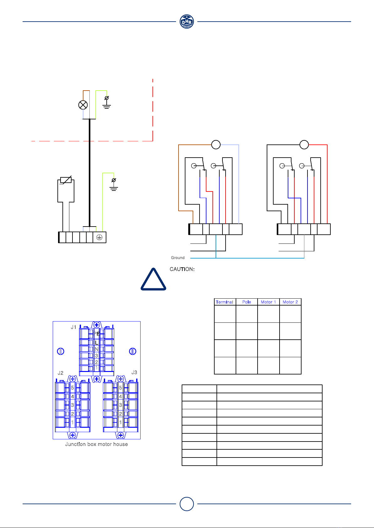
5. WIRING DIAGRAMS
M
M
PTC Heater 12- 24V 30W,
Motor house
Power for LEDdriver
L1
S1, S2, S3, S4
PTC
J2, J3
J1
M1
X6
M2
X3, X4, X5
Component
J2 J3
1
Junction box motor house
1
2
3
4
5
1
2
4
3
5
N
J1
2
3
L
PE
-
Ground
+
J3-2
J3-3
J3-4
Motor 12VDC/6W, gearhead 1:100 (right / left)
Head resisting cable 3 x1,5 - 1,25 m
Special spindle Motor 25W (up / down)
Mounting wire 1,5 mm², green/yellow (earth)
Description
Terminal block 5 way - Motors
Terminal block 6 way - Mains
PTC heater 12-24V 30W (self-regulating)
Halogen lamp
Microswitch V3 with roller lever, IP67 sealed
Motor 1
-
Down
Up
-
+
Ground
-
J2-2
J2-3
J2-4
-
Ground
+
J2-2
J2-3
J2-4
+
Ground
-
J3-2
J3-3
J3-4
Pole
Terminal
-
Left
Right
-
Motor 2
Motor Up / down
6 - 13VDC
S1
1
L = 100mm
J1
X3
X6
N123L
PTC
(Mounting plate motor house)
Ground
CAUTION:
Ground is used as return pad when on the end-position switch.
Always use the ground from the control panel to avoid unwanted
potential differences.
(Drum)
Head searchlight
L1
Motor left / right
6 - 13VDC
J2
3542 54123 J3
S2
M1
S4S3
M2
A. Internal Connections
!

15 Version 1.0 October 2018
Den Haan Rotterdam
B. External Connections
Motor up / down
3
F2A
Voltage 24VDC
F3A
1 2
6-13VDC
Beam On/Off
LEDdriver
23LN
PTC Heater
230VAC
1J1 532
6-13VDC
- +
J2 J3
- +
1 454
Motor left / right
F0.5AF1A
Joystick
(Four directions
and neutral)
Voltage 230VAC

16 Version 1.0 October 2018
Den Haan Rotterdam
L N PE
230VAC
5 x 1 mm²
4
587691012 11
24VDC
321
F2A
K1 2414
2313
Motor housing
PTC Heater
1
Motor up / down
F3A
Powerfor LEDdriver
J2
2
5
4
3
2
3
1
PE
N
L
J1
Motor left / right
3 x 1,5 mm²
1
J3
5
4
3
2
C. Control panel

17 Version 1.0 October 2018
Den Haan Rotterdam
3 x 1,5 mm²
L N PE
230VAC
1
4
7
1112 10 9 678 5
24VDC
13 K3**56
123
F2A
8
14
K1 14
24
13 13
23
Motor housing
PTC Heater
11
1
5 x 1 mm²
Motor up / down
F3A
1 09
14
Powerfor LEDdriver
5
3
4
2
J2
3
2
1
J1
L
N
PE
** K3 not standard in delivery
Coil operating range 70-110%
Motor left / right
12
4
3
2
J3
5
2
3
4
1
24
23
9
1112 10
K2
568 7 3214
D. Dual control panel

18 Version 1.0 October 2018
Den Haan Rotterdam
LN PE
230VAC
5 x 1 mm²
24VDC
See table 1
K1
Motor housing
PTC Heater
1
Motor up / down
F3A
Powerfor LEDdriver
J2
2
5
4
3
2
3
1
PE
N
L
J1
Motor left / right
3 x 1,5 mm²
1
J3
5
4
3
2
21 364 5
T1AS2
12/24VDC
E. Joystick
19 Version 1.0 October 2018
Den Haan Rotterdam
6. MAINTENANCE AND CORRECT USE
Tips for correct use
• Do not overheat the searchlight - max. burning time 20 min.
• Switch off the searchlight immediately after use, this increases the life
expectancy of the bulb
• Do not light-up objects closer than 2 metres
• Clean the searchlight regularly with water
• Do not point the light beam at the eyes of humans or animals
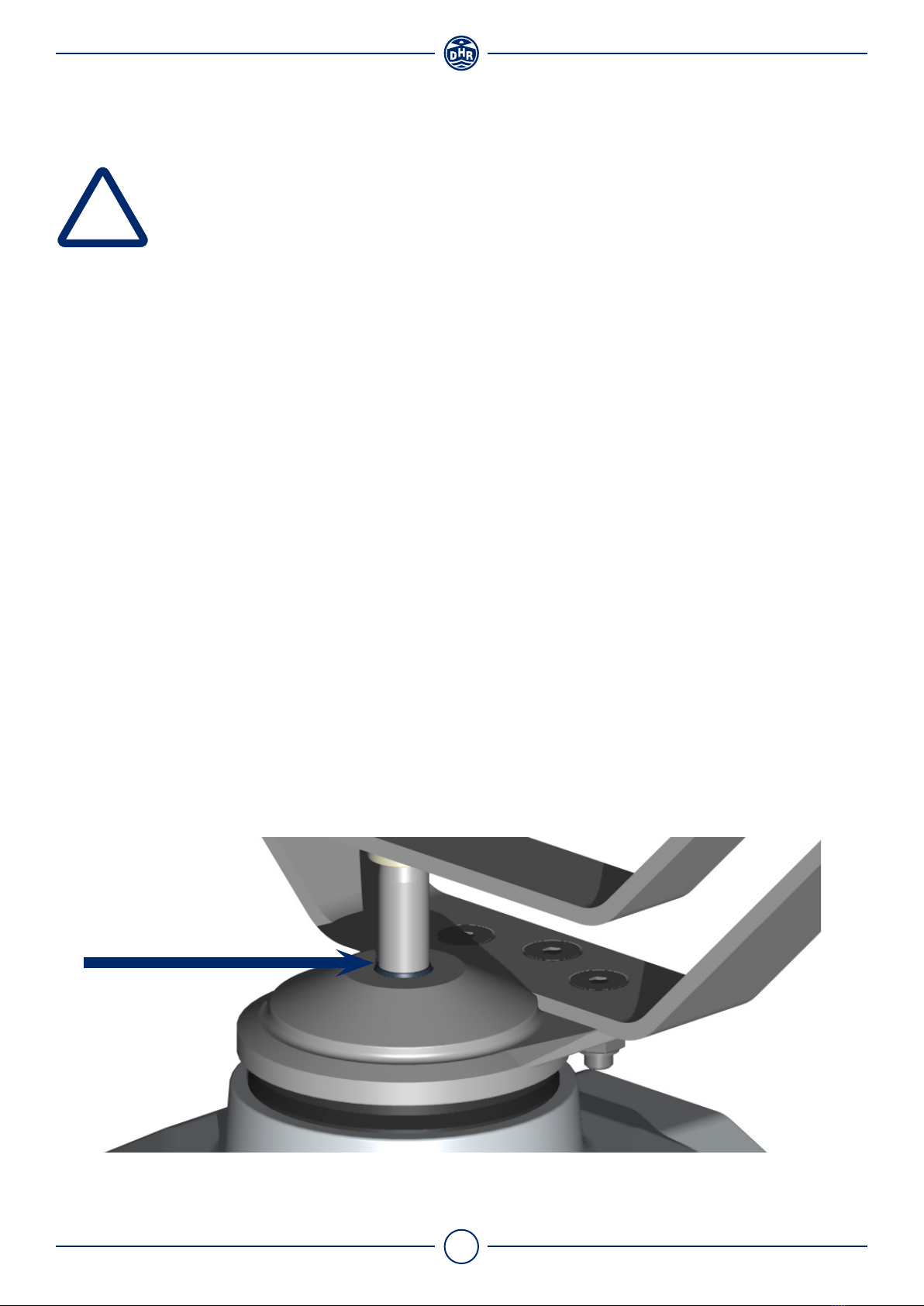
Preventive maintenance
Clean the searchlight with clean water regularly. Do not use any aggressive cleaning agents. At least twice
a year rub the dirt wiper, on top of the motor housing (see drawing below), in with silicone grease.
Safety notes
• Handle with care
•Turn off main power
• Warning, lamp is hot
!

20 Version 1.0 October 2018
Den Haan Rotterdam
7. REPLACING OF MOTOR FRAME
Motor frame replacement
1. Switch off the main power
2. Open the backplate of the motor housing
3. Disconnect the power cables connected to the motor frame
4. Unscrew the four (4) bolts to dismount the searchlight from the base structure
5. Unscrew the spindle nut
6. Tilt the searchlight vertically
7. Disassemble the bottom plate
8. Unscrew the (4) bolts and carefully remove the defective motor frame
9. Slowly insert the new motor frame in the motor housing. Be careful not to damage the dirt wiper
located on top of the motor housing
10. Before fixing the (4) bolts of motor frame, the following steps should be taken:
A. Reconnect the power cables
B. Turn the motors left/right and up/down using the controls. This is necessary to settle the motor
frame inside the motor housing
11. Close the motor housing by mounting the bottom plate
12. Reposition the searchlight and mount it on the base structure
13. Fasten the spindle nut. Do not overtighten it!
14. Test the searchlight both in vertical and horizontal directions to ensure that the searchlight is function-
ing properly
15. Searchlight is ready for use
Spindle nut
Bottom plate
Four bolts
Dirt wiper
1
1
2
2
4
3
3
5
Motor frame
5
4
!
!
Table of contents
Other DHR Floodlight manuals


