Di-soric ID-01 User manual

ID-01 Laser Scanner
User’s Manual
ID-01 User’s Manual

ii ID-01 Laser Scanner User’s Manual
Copyright and Disclaimer
Copyright ©2010
ISO 9001 Certified
Issued by TüV USA
All rights reserved. The information contained herein is proprietary and is provided solely for the purpose
of allowing customers to operate and/or service di-soric manufactured equipment and is not to be
released, reproduced, or used for any other purpose without written permission of di-soric.
Throughout this manual, trademarked names might be used. Rather than place a trademark (™) symbol
at every occurrence of a trademarked name, we state herein that we are using the names only in an editorial
fashion, and to the benefit of the trademark owner, with no intention of infringement.
Disclaimer
The information and specifications described in this manual are subject to change without notice.
Latest Manual Version
For the latest version of this manual, see the Download Center on our web site at:
www.di-soric.com.
Technical Support
Warranty and Terms of Sale
For Standard Warranty information contact:
di-soric GmbH & Co. KG
Steinbeisstraße 6
DE-73660 Urbach
Fon: +49 (0) 71 81 / 98 79 - 0
Fax: +49 (0) 71 81 / 98 79 - 179
www.di-soric.com

ID-01 Laser Scanner User’s Manual iii
Introduction
Table of Contents
Chapter 1 Quick Start
Step 1 Check Hardware...........................................................................1-2
Step 2 Connect the System .....................................................................1-3
Step 3 Position Symbol and Scanner ......................................................1-4
Step 4 Install di-soric ID...........................................................................1-5
Step 5 Select Scanner Model ..................................................................1-6
Step 6 Autoconnect .................................................................................1-7
Step 7 Test for Read Rate .......................................................................1-8
Step 8 Calibrate the Scanner...................................................................1-9
Step 9 Save Calibration Settings for Power-On.....................................1-10
Step 10 Configure the Scanner .............................................................1-11
Chapter 2 Using di-soric ID
Setup Mode .............................................................................................2-2
Application Mode .....................................................................................2-3
Dropdown Menus.....................................................................................2-4
Connect Menu ........................................................................................ 2-9
View ...................................................................................................... 2-11
Navigating in di-soric ID.........................................................................2-12
Send/Receive Options ...........................................................................2-13
Chapter 3 Communications
Communications by di-soric ID ................................................................3-2
Communications by Serial Command .....................................................3-2
Password Protection................................................................................3-3
RS-232/422 Host Port..............................................................................3-4
RS-232 Auxiliary Port ............................................................................3-11
Preamble ...............................................................................................3-20
Postamble..............................................................................................3-21
LRC Status ............................................................................................3-22
Intercharacter Delay ..............................................................................3-22
Chapter 4 Read Cycle
Read Cycle by di-soric ID ........................................................................4-2
Read Cycle by Serial Command..............................................................4-2
Multisymbol..............................................................................................4-3
Number of Symbols .................................................................................4-4
Serial Trigger .........................................................................................4-12
End of Read Cycle.................................................................................4-14
Decodes Before Output .........................................................................4-16
Scanner Setup .......................................................................................4-17
Laser Setup ...........................................................................................4-21
Chapter 5 Symbologies
Symbologies by di-soric ID ......................................................................5-2

iv ID-01 Laser Scanner User’s Manual
Table of Contents
Symbologies by Serial Command ........................................................... 5-2
Code 39 ................................................................................................... 5-3
Code 128 ................................................................................................. 5-6
Interleaved 2 of 5................................................................................... 5-10
Codabar................................................................................................. 5-13
UPC/EAN............................................................................................... 5-16
Code 93 ................................................................................................. 5-19
Pharmacode .......................................................................................... 5-20
Narrow Margins ..................................................................................... 5-22
Symbology ID ........................................................................................ 5-23
Background Color.................................................................................. 5-24
Autodiscriminate .................................................................................... 5-24
Symbol Ratio Mode ............................................................................... 5-25
Chapter 6 I/O Parameters
Output Conditions by di-soric ID Menu.................................................... 6-2
I/O Parameters by Serial Command........................................................ 6-3
Symbol Data Output ................................................................................ 6-4
Message Output ...................................................................................... 6-7
No Read Message................................................................................... 6-8
Bad Symbol Message.............................................................................. 6-9
No Symbol Message ............................................................................. 6-10
Beeper................................................................................................... 6-11
Partial Output......................................................................................... 6-12
Serial Verification................................................................................... 6-13
EZ Button............................................................................................... 6-15
Output 1................................................................................................. 6-18
Output 2................................................................................................. 6-24
Output 3................................................................................................. 6-25
Quality Output........................................................................................ 6-26
Chapter 7 Matchcode
Matchcode by di-soric ID ......................................................................... 7-2
Matchcode by Serial Command .............................................................. 7-2
Overview of Matchcode ........................................................................... 7-3
Using Master Symbols............................................................................. 7-3
Matchcode Type ...................................................................................... 7-4
New Master Pin ....................................................................................... 7-9
Master Symbol Database ...................................................................... 7-10
Chapter 8 Diagnostics
Diagnostics by di-soric ID ........................................................................ 8-2
Diagnostics by Serial Command ............................................................. 8-2
Diagnostic Messages Overview .............................................................. 8-3
Counts ..................................................................................................... 8-4
Hours Since Last Reset........................................................................... 8-6
Laser High ............................................................................................... 8-7

ID-01 Laser Scanner User’s Manual v
Introduction
Laser Low ................................................................................................8-8
Service Message .....................................................................................8-9
Chapter 9 Calibration
Calibration................................................................................................9-2
Auto Frame ..............................................................................................9-6
Chapter 10 Terminal
Terminal Window ...................................................................................10-2
Find Function .........................................................................................10-3
Macros ...................................................................................................10-4
Terminal Window Functions ..................................................................10-5
Chapter 11 Utilities
Utilities by di-soric ID .............................................................................11-2
Summary of Utilities Commands ...........................................................11-3
Read Rate..............................................................................................11-5
Counters ................................................................................................11-6
Master Database ...................................................................................11-8
Digital Bar Code...................................................................................11-11
Firmware..............................................................................................11-12
Device Control .....................................................................................11-13
Symbol Type........................................................................................11-15
Defaulting/Saving/Resetting ................................................................11-16
di-soric Grading ...................................................................................11-17
Reader Status Requests......................................................................11-19
Appendices
Appendix A General Specifications ........................................................ A-2
Appendix B Electrical Specifications....................................................... A-5
Appendix C Serial Configuration Commands ......................................... A-6
Appendix D Serial Command Format ..................................................... A-9
Appendix E ASCII Table ....................................................................... A-11
Appendix F Defaulting/Saving/Resetting .............................................. A-13
Appendix G Symbol Configuration........................................................ A-15
Appendix H Object Detector ................................................................. A-17
Appendix I Formulas for Number of Decodes....................................... A-18
Appendix J Operational Tips................................................................. A-21
Appendix K Interface Standards ........................................................... A-22
Appendix L Multidrop Communications ................................................ A-23
Appendix M Troubleshooting ................................................................ A-28
Appendix N Glossary of Terms............................................................. A-30

vi ID-01 Laser Scanner User’s Manual
About the ID-01 Laser Scanner
About the ID-01 Laser Scanner
The ID-01 is an ultra-compact scanner that can decode high density symbols from 2 to 10
inches at a 70 degree scan angle, at speeds of 300 to 1,000 decodes per second, with a
power draw of only 300mA at 5V. The multi-function EZ button can be used for read rate
tests and automatic calibration right out of the box, and it can also be programmed to per-
form a variety of other functions.
Programmable firmware also allows considerable control of multiple features, including
three programmable relay outputs and new master and trigger inputs.
The scanner can be configured with di-soric ID (Setup Program), di-soric’s proprietary
scanner setup software. di-soric ID can be downloaded from the di-soric website at
www.di-soric.com. You must be running Microsoft Windows 2000 or higher to use
di-soric ID.
Scanner Communication
There are five ways to program the scanner:
1. di-soric’s Windows-based di-soric ID, which offers point-and-click ease of use and
visual responses to user adjustments.
2. Serial commands such as <K100,1> can be sent from di-soric ID’s Terminal or
another terminal program.
3. Embedded firmware (onboard menus).
4. Symbol configuration.
5. The EZ Button on the top of the scanner.
Note: You can learn the current setting of any parameter by inserting a question mark after
the command number, as in <K100?> To see all “K” commands, send <K?>.

ID-01 Laser Scanner User’s Manual vii
Introduction
Warning and Caution Summary
This equipment has been tested and found to comply with the limits for a Class A digital
device, pursuant to part 15 of the FCC Rules. These limits are designed to provide reasonable
protection against harmful interference in a residential installation. This equipment generates,
uses, and can radiate radio frequency energy, and, if not installed and used in accordance
with the instructions, may cause harmful interference to radio communication. However,
there is no guarantee that interference will not occur in a particular installation. If this
equipment does cause harmful interference to radio or television reception, which can be
determined by turning the equipment off and on, the user is encouraged to try to correct
the interference by one or more of the following measures:
• Reorient or relocate the receiving antenna;
• Increase the separation between the equipment and receiver;
• Connect the equipment into an outlet on a circuit different from that to which the receiver
is connected;
• Consult the dealer or an experienced radio/TV technician for help.
For connection to a UL-listed direct plug-in power unit marked Class II and rated 10 to 28
VDC at 5 watts or greater.
European models must use a similarly rated Class I or Class II power supply that is certified
to comply with standard for safety EN 60950.
Use of controls, adjustments, or performance of procedures other than those specified
herein may result in hazardous laser light radiation exposure.
There are no user-serviceable parts in the scanner. Opening the scanner voids the di-soric
Systems, Inc. warranty and could expose the user to laser diode power.
The laser beam can be harmful to eyesight. Avoid eye contact with the laser beam. Never
point the beam at other people, or in a direction where people may be passing.

viii ID-01 Laser Scanner User’s Manual
Warning and Caution Summary
Warning and Caution Summary (cont.)
The following label is located on side of the ID-01 Laser Scanner:
• Embedded Laser Diode - 650nm, 12mW
• Wavelength: 650nm
• Beam Divergence: 0.6˚(typ.)
• Pulse Duration: 38μs
• Maximum Power: 1mW
• Standard - IEC-60825-1 Ed. 2(2007)
Location of the ID-01’s laser aperture:
CAUTION: Use of controls or adjustments or performance of procedures other than those
specified herein may result in hazardous radiation exposure.
IMPORTANT: The ID-01 is intended for connection to a UL-listed direct plug-in power unit
marked Class 2 and rated 5 VDC at 3.5 Watts, or greater if using electrical accessories.
European models must use a similarly rated Class 1 or Class 2 power supply that is certified
to comply with standard for safety EN 60950.
Laser Aperture

ID-01 Laser Scanner User’s Manual ix
Introduction
Warning and Caution Summary (cont.)
Warning Label Placement
These labels are located on the ID-01 Laser Scanner:

xID-01 Laser Scanner User’s Manual
Statement of Agency Compliance
Statement of Agency Compliance
This device has been tested in accordance with IEC 60825-1 2nd ed., and has been certified
to be under the limits of a Class 2 Laser device.
The ID-01 has been tested for compliance with FCC (Federal Communications Commission)
regulations and has been found to conform to all applicable FCC Rules and Regulations.
To comply with FCC RF exposure compliance requirements, this device must not be co-located
or operate in conjunction with any other antenna or transmitter.
Changes or modifications not expressly approved by the party responsible for compliance
could void the user’s authority to operate the equipment.
The ID-01 has been tested for compliance with CE (Conformité Européenne) standards
and guidelines, and has been found to conform to applicable CE standards, specifically
the following requirements:
Radiated Emissions: EN 55022:2006 Class A 30-1000 MHz
Conducted Emissions: EN 55022:2006 Class A .15-30 MHz
The ID-01 has been tested by an independent electromagnetic compatibility laboratory in
accordance with the applicable specifications and instructions.
The ID-01 is compliant with FDA performance standards for laser products except for
deviations pursuant to laser notice no. 50, dated June 24, 2007.

ID-01 Laser Scanner User’s Manual xi
Introduction
Statement of RoHS Compliance
All di-soric ID readers are RoHS-Compliant.
These products meet all the requirements of the European Parliament and the Council of the
European Union for RoHS compliance. In accordance with the latest requirements, our
RoHS-compliant products and packaging do not contain intentionally added Deca-BDE,
Perfluorooctanes (PFOS) or Perfluorooctanoic Acid (PFOA) compounds above the
maximum trace levels. To view the documents stating these requirements, please visit:
http://eur-lex.europa.eu/LexUriServ/LexUriServ.do?uri=CELEX:32002L0095:EN:HTML
and
http://eur-lex.europa.eu/LexUriServ/LexUriServ.do?uri=OJ:L:2006:372:0032:0034:EN:PDF
Please contact your sales manager for a complete list of di-soric’s RoHS-Compliant
products.
This declaration is based upon information obtained from sources which di-soric believes to be reliable, and from
random sample testing; however, the information is provided without any representation of warranty, expressed or
implied, regarding accuracy or correctness. di-soric does not specifically run any analysis on our raw materials or
end product to measure for these substances.
The information provided in this certification notice is correct to the best of di-soric’s knowledge at the date of
publication. This notice is not to be considered a warranty or quality specification. Users are responsible for
determining the applicability of any RoHS legislation or regulations based on their individual use of the product.

xii ID-01 Laser Scanner User’s Manual

ID-01 Laser Scanner User’s Manual 1-1
1Quick Start
Contents
This section is designed to get your scanner up and running quickly. When connected to a
host computer with Windows™ operating system (2000 or above), you can use di-soric
ID (Setup Program) to configure and control your ID-01 Laser Scanner. In addition
to di-soric ID, you can send commands to your scanner by serial command and by the
scanners’s embedded menus.
Step 1 Check Required Hardware................................................................................................ 1-2
Step 2 Connect the System.......................................................................................................... 1-3
Step 3 Install di-soric ID................................................................................................................ 1-4
Step 4 Select Scanner Model in di-soric ID.................................................................................. 1-5
Step 5 Autoconnect ...................................................................................................................... 1-6
Step 6 Position Symbol and Scanner........................................................................................... 1-7
Step 7 Test Read Rate................................................................................................................. 1-8
Step 8 Calibrate the Scanner ....................................................................................................... 1-9
Step 9 Save Calibration Settings for Power-On ......................................................................... 1-10
Step 10 Configure the Scanner .................................................................................................. 1-11
1-2 ID-01 Laser Scanner User’s Manual
Hardware Required
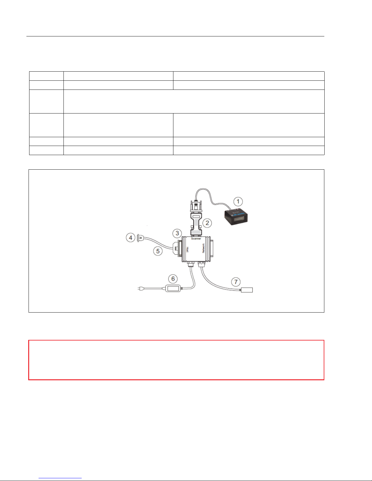
Step 1 — Hardware Required
Item Part Number Description
1ID-01-LX-X-S ID-01 Scanner
2
Host Computer (running Windows 2000 or higher,
and with di-soric ID or a terminal communications
pro-
gram such as HyperTerminal)
3VSID-K-25S/9K-2
Cable, Setup, DB-25 Plug to DB-9 Socket, 6 ft. (If
using another host cable, be certain it does not
have RTS/CTS connected to the host.)
4VSID-IB-S Interface Device
6VSID-PS-24V-ES Voltage Converter
Figure 1-1 ID-01Hardware Configuration
Caution: If using your own power supply, be certain that it is wired correctly and
supplied voltage is within the +10-28VDC limits. Incorrect wiring or voltage can
cause software or equipment failures.

ID-01 Laser Scanner User’s Manual 1-3
Quick Start
Step 2 —Connect the System
1. Connect the scanner to the VSID-PS-24V-ES and connect the VSID-PS-24V-ES to the
VSID-IB-S.
2. Connect the VSID-IB-S 25-pin connector to the host computer.
3. Connect the power supply to the VSID-IB-S’s POWER connector.
4. Apply power to system.
Note:
RS-232 cabling from the 15-pin connector to the host can be up to 47 feet pro-
vided it does not include 5VDC input.
Note: If using your own null modem RS-232 host cable, be certain that the host’s TxD
connects to the scanner’s RxD and the scanner’s TxD connects to the host’s RxD.
Figure 1-2 ID-01 Hardware Configuration
Caution: Be sure that all cables are connected BEFORE applying power to
the system. Always power down BEFORE disconnecting any cables.

1-4 ID-01 Laser Scanner User’s Manual
Install di-soric ID
Step 3 —Install di-soric ID
Once your scanner is connected to a host computer with Windows™ operating system
(2000 or above), you can use di-soric ID (Setup Program) for configuration and control.
To install di-soric ID from a USB Stick:
• Insert your di-soric USB Stick in your computer.
• Select the “Configuration Software” file, launch Setup.exe under “di-soric ID”, and follow
the prompts.
To download di-soric ID from the Web:
• Go to www.di-soric.com.
• Navigate through the following sequence: Download > Software > Barcode Scanner
• Click the Download button and store the di-soric ID.zip file to the location of your
choice on your hard drive.
• Extract the di-soric di-soric ID WinZip files to a directory of your choice.
• At the end of the install process, copy a shortcut di-soric ID icon onto your desktop.
• Click the di-soric ID icon to run the program.

ID-01 Laser Scanner User’s Manual 1-5
Quick Start
Step 4 —Select Scanner Model in di-soric ID
When you start the program, the following menu will appear:
5. Select ID-01 Laser from the menu and click OK. If you do not want to make this
selection every time you load di-soric ID, uncheck “Show this window at Startup”.
6. Select the default
name
(
ID-01 Laser-1) or type in a file name of your choice and click
OK.
7. Click Yes when the following dialog box appears:
Note: If you need to select another model later, you can find it in App Mode under Model
on the menu bar.

1-6 ID-01 Laser Scanner User’s Manual
Autoconnect
Step 5 —Autoconnect
1. In the Connecting... dialog, if your communications port is not the default COM1,
use the pull down arrow to change your communications port.
2. Click the Start button.
When connected, the scanner’s settings will be loaded into di-soric ID and the CON-
NECTED message will appear in a green box in the status bar at the bottom right of your
screen.
3. If the connection fails, enable a different Com Port, check connections, and try again.
Tip: If you do not see the CONNECTED or DISCONNECTED message at the bottom of
your dialog, try expanding the di-soric ID window horizontally.

ID-01 Laser Scanner User’s Manual 1-7
Quick Start
Step 6 —Position Symbol and Scanner
Note: Code 39 is the default code type enabled. If you are uncertain as to your symbology
type, enable all codes by selecting the Auto Discriminate macro in Terminal mode.
1. Set up a symbol at the distance you are using in your application.
2. Avoid bright light or IR light from other sources, including other scanners.
3. Pitch the symbol or scanner at a minimum of ±15° to avoid specular reflection (the
return of direct, non-diffused light).
Note: If using an I 2/5 symbol, verify that the number of characters in the symbol being
scanned matches the symbol length enabled for the I 2/5 symbol type (default is 10 and
6). See “Interleaved 2 of 5” on page 5-10.
Symbol/Scanner Positioning

1-8 ID-01 Laser Scanner User’s Manual
Test Read Rate
Step 7 —Test Read Rate
With this test you can learn the percentage of decodes per images captured by observing
the LEDs (20% through 100%) on the top of the ID-01 which are active during a read rate
test. If the results are not satisfactory, move on to Step 8 — “Calibrate the Scanner”.
By di-soric ID
After connecting to the scanner, di-soric ID will open in Setup Mode.
1. Click the EZ Button in Setup Mode to begin the read rate test.
2. Follow the instructions in Setup Mode.
3. To end the read rate test, click the Stop button.
By the EZ Button
1. Press and hold the EZ button on the ID-01 until
you hear one beep and see one LED momentarily
turn amber. This will signal the beginning of the
read rate routine.1
2. To end the read rate test press the EZ button and
quickly release.
1. This assumes that the default functions of the EZ button have not been re-programmed.
Other manuals for ID-01
1
Table of contents
Other Di-soric Scanner manuals


