diamond mowers ALL AMERICAN DISC User manual
DIAMONDMOWERS.COM
3-POINT HITCH
ALL AMERICAN DISC
OPERATOR’S MANUAL

PRODUCT INFORMATION
Record the model and serial number of your unit here. When calling for
warranty, service or parts, you may be asked to provide this information,
in order to ensure fast, accurate service.
MODEL:All American Disc
SERIAL NUMBER:___________________________________________________
© Diamond Mowers, LLC
All rights reserved.
Any failure to read, understand and follow the instructions found in this operator’s
manual could lead to serious injury. Operators who choose to operate this equipment
without following instructions, or who choose to operate this equipment in a manner
inconsistent with the recommendations set forth in this manual, do so at their own
risk and assume the risk of injury. Diamond Mowers will not be liable for an owner
or operator’s loss, damage, or injury due to the misuse of the equipment, failure to
understand the inherent risks, or inability to properly operate the equipment.
2

WELCOME!
Thank you for choosing Diamond Mowers, and welcome to your All American
Disc. Before you begin operating, we encourage you to look through this
manual to review the proper maintenance and operating techniques that will
keep you, and your equipment, safe — while ensuring you the most productive
road grader in the market.
We have nothing but respect and admiration for you. Our job at Diamond is
to provide you with the toughest, most reliable and safest equipment that
will allow you to do your job better. That also means being there when you
need us.
CONTACT US:
Parts: 888.960.0361 | parts@diamondmowers.com
Main Office:800.658.5561 | 605.977.3300
Website: www.diamondmowers.com |Email: inf[email protected]
Your time is important to us.
We guarantee that Genuine Diamond Parts will ship within 72-hours of the
order being placed or the parts and shipping are free.
Your satisfaction is guaranteed.
If you are not completely satisfied with your new Diamond in the first
30-days, we will buy it back. No questions asked.
Thanks again for choosing Diamond.
If at any time your needs are not being met by our team, please feel free
to call me direct.
Tim Kubista
VP Sales & Marketing
651.955.6665

OWNER REGISTRATION
In your welcome packet you should have received a warranty registration
form. Complete and return this form to our main office. It’s a self-mailer,
so no postage is required.
If you’d rather complete this info online, go to:
http://info.diamondmowers.com/register-my-product
Returning your registration information to Diamond will help us process any
warranty claims quickly and efficiently – so you can get back to work, fast.
TRANSFERRED OWNERSHIP
If you have acquired this All American Disc from a previous owner, we
encourage you to register your equipment online. By registering your
Diamond Mowers unit, you’ll stay informed on product advancements,
offers and service alerts.
Register by going to: http://info.diamondmowers.com/register-my-product
We honor our equipment’s warranty from the date it was put into service,
no matter who’s in charge of running it.
For any questions, contact our Warranty / Service team at:
888.960.0364 or 605.977.3300
PRODUCT REGISTRATION
4

INTENDED USE 6
TAKE A LOOK AROUND 7
GETTING STARTED 8
OPERATING THE ALL AMERICAN DISC 10
MAINTENANCE 14
TROUBLESHOOTING 17
PARTS BOOK 19
INDEX 27
TABLE OF CONTENTS

INTENDED USE
Do not operate this unit without first reading the safety precautions
and operating instructions in this manual.
This attachment is designed to be used for the grading of gravel
road shoulder applications.
This includes:
•Removing berms along the roadside edge.
•Reclaim gravel lost during grading.
•Removing clumps of rooted material along the transition of road to ditch.
•Contouring asphalt shoulders.
This attachment should only be used in an area free of obstructions and
bystanders. Any use on non-vegetative material, or in an area that is not
clear of persons and property, is strictly prohibited. Any use outside of the
aforementioned application is considered contrary to its intended use. Any
damage that may occur as a result of misuse will void warranty as stated in
Diamond Mowers’ warranty policy.
Do not operate this unit without first reading the safety precautions
and operating instructions in this manual.
6
TAKE A LOOK AROUND
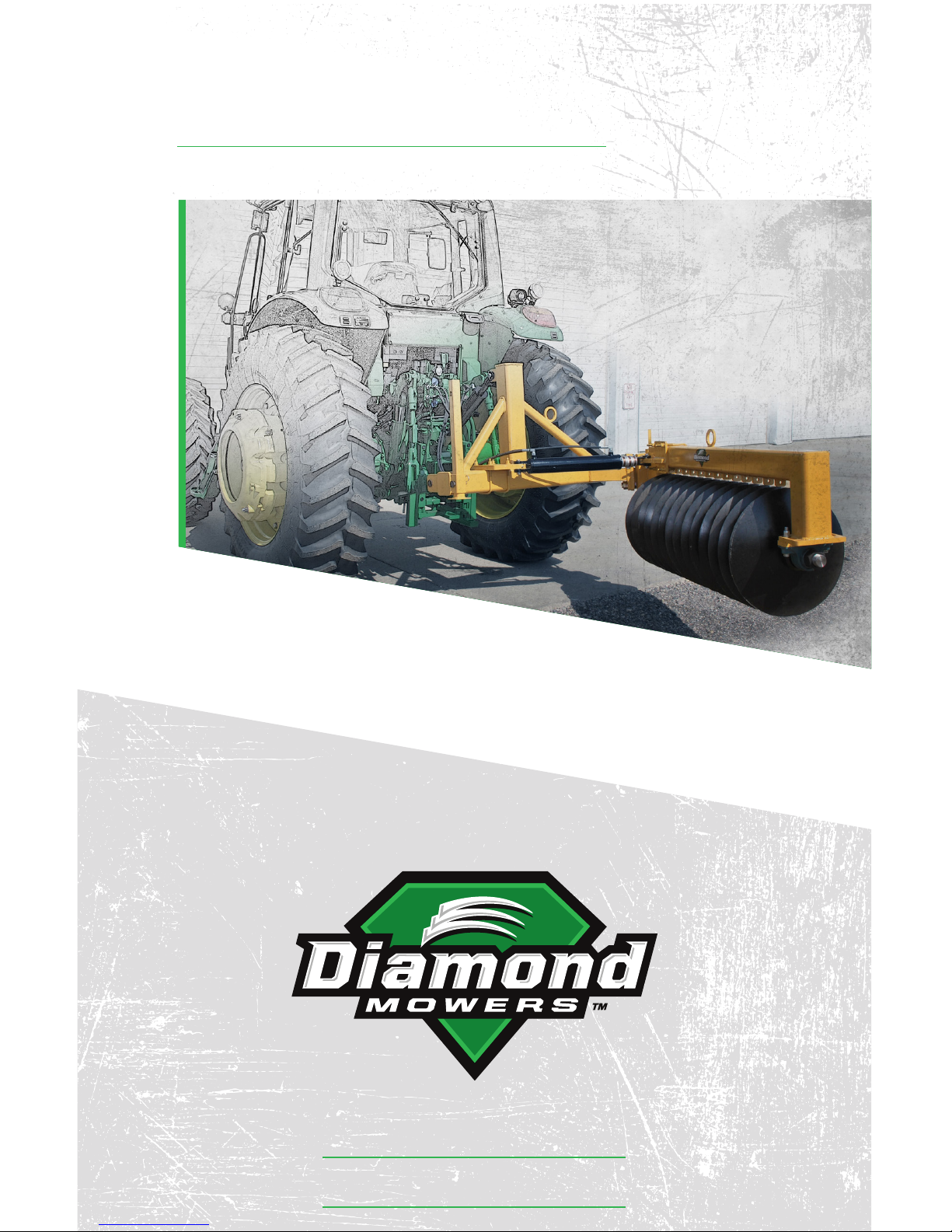
DISC HOUSING
The disc housing contains (14) 22”
(559mm) hardened steel convex
discs, for long life with
superior performance.
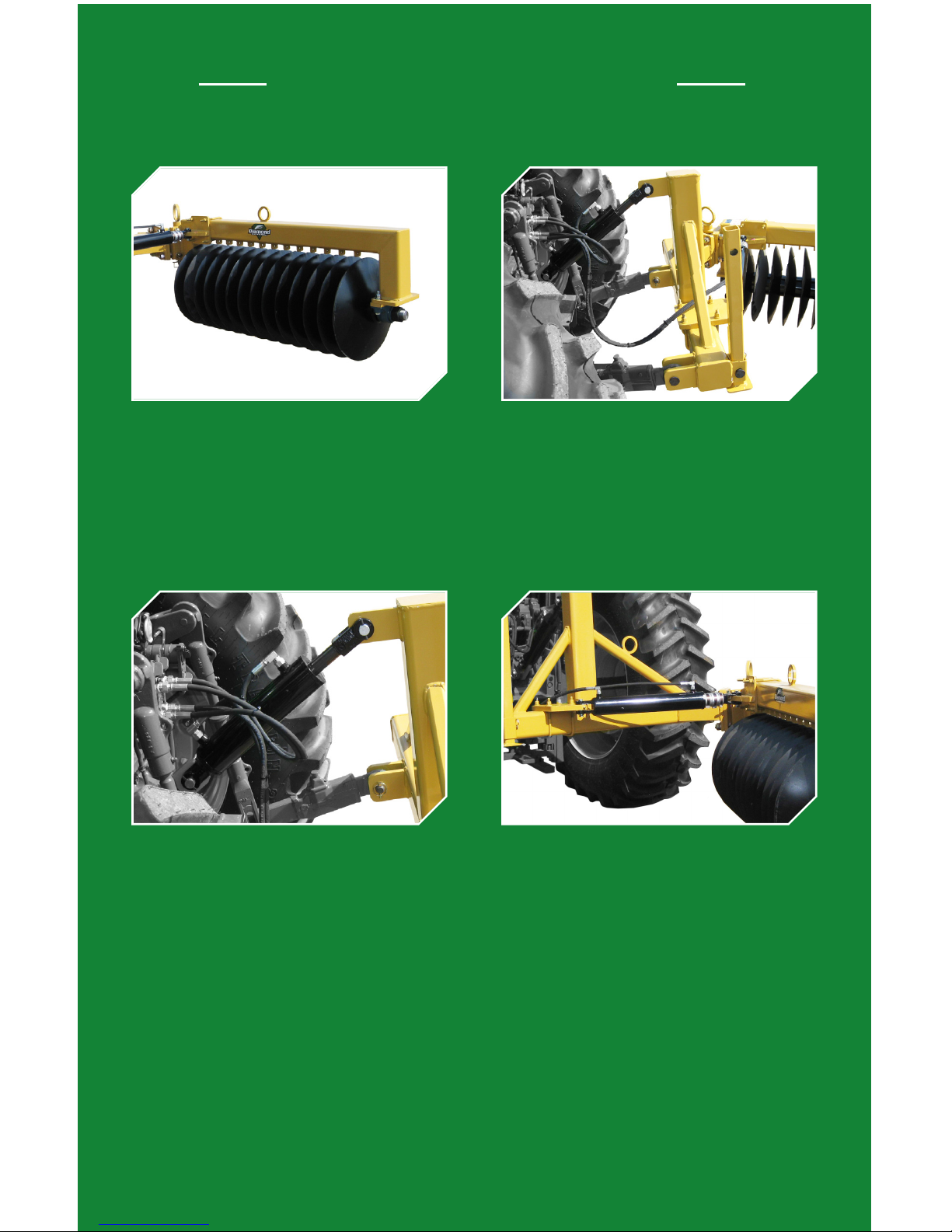
HITCH FRAME
The unit includes an easy to mount
hitch frame, compatible with all
category II 3-Point hitches.
SWING CYLINDER (OPTIONAL)
An optional swing cylinder is
available; allowing the operator
to swing the disc housing in for
storage and transport, or out for
cutting operations.
PITCH CYLINDER
Standard equipment is a hydraulic
cylinder that controls the pitch
of the disc housing, allowing the
operator to control the angle and
depth of the cutting discs for
optimum performance.
7
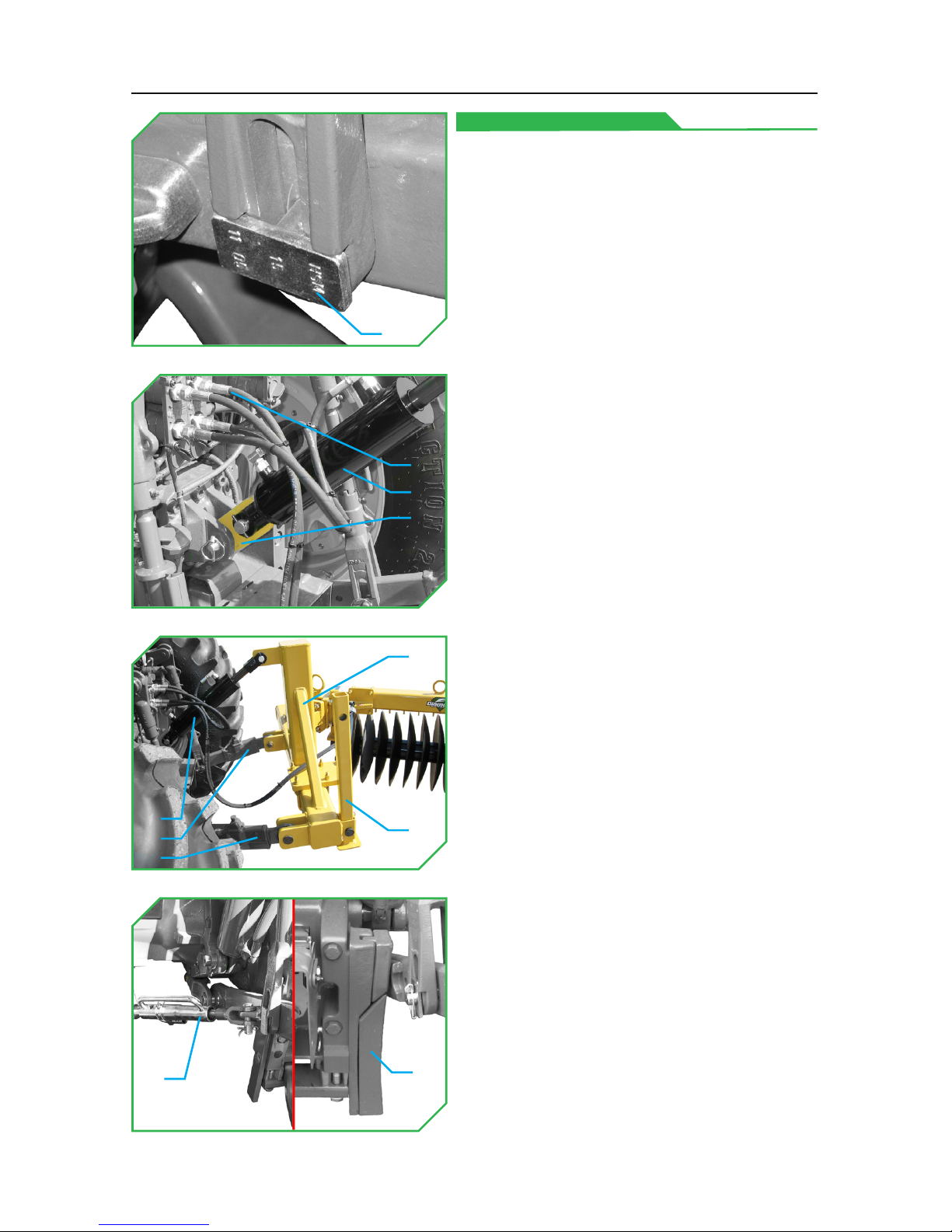
GETTING STARTED
MOUNTING THE DISCS
Reference the tractor’s operator manual
for information on adjusting the draft
links(1) and anti-sway bars/spacers(2)(3) (if
present) on the tractor’s 3-Point hitch.
This unit requires a Catagory II hitch.
•Adjust the 3-Point hitch draft links(1)
to the fixed (non-floating) position.
◦NOTE: Draft links vary in
appearance for various
tractor models (if present).
•Replace the factory 3-Point upper
hitch link with the cylinder link(4).
•Mount the pitch cylinder(5) to the
cylinder link(4) with its hardware.
◦NOTE: Reference the parts pages
for additional clarification.
•Connect draft beams “A”(6) and “B”(7)
and the pitch cylinder(5) to the hitch
frame(8) with the QD pins and lynch
pins.
•Raise the stand(9) and secure it in
place with its pin and lynch pin.
◦NOTE: lower the stand when
removing the All American Disc
from the tractor.
•Connect the hydraulic hoses(10) to
the tractor’s auxiliary remotes.
•Adjust the 3-Point hitch anti-sway
bars/spacers(11)(12) to minimize
horizontal sway of the discs.
◦NOTE: Anti-sway bars/spacers
vary in appearance for various
tractor models (if present).
(1)
(11) (12)
(5)
(10)
(4)
(6)
(7)
(5) (9)
(8)
8
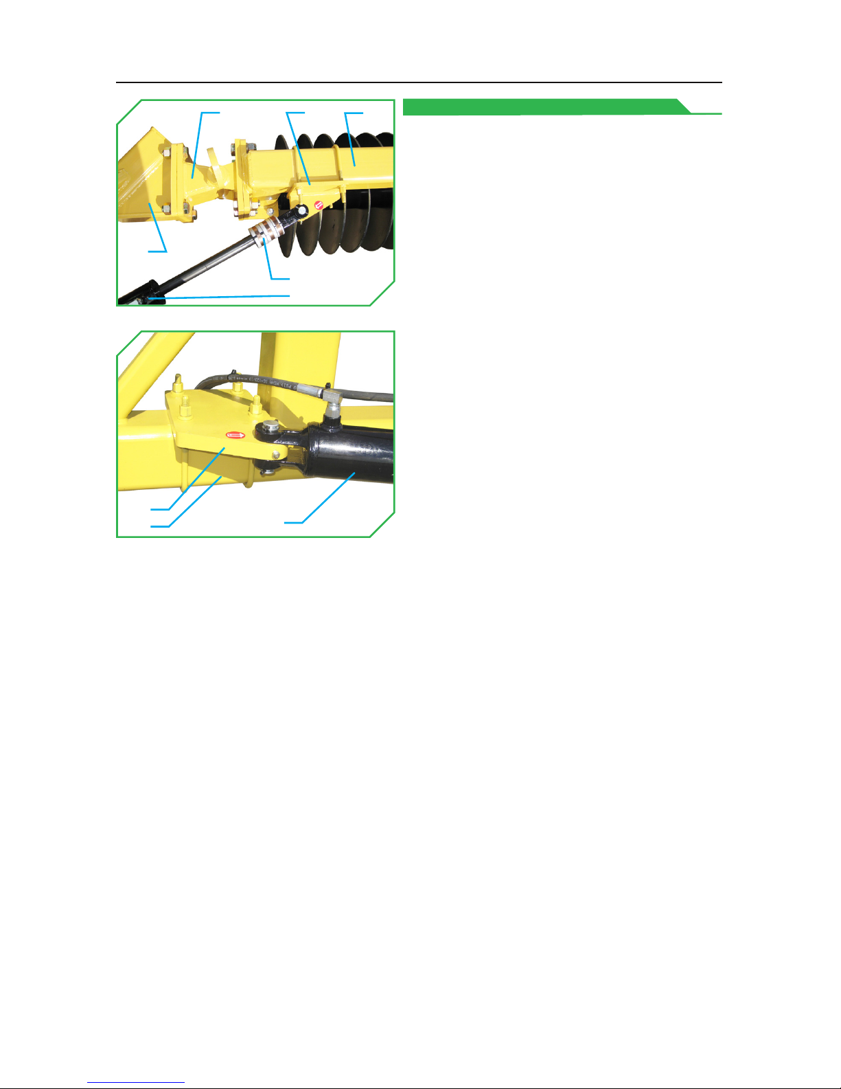
MOUNTING THE SWING CYLINDER
The swing cylinder is OPTIONAL, and
may not be present. Reference the parts
pages in this manual for additional
clarification.
•Unbolt the disc housing(13) from the
hitch frame(14).
•Mount the swivel assembly(15)
between the disc housing(13) and
hitch frame(14).
•Mount the base anchor(18) to the
hitch frame(14).
•Mount the base end of the swing
cylinder(19) to the base anchor(18).
•Swing the disc housing(13) until the
swivel assembly(15) is straight.
•Mount the rod anchor(16) to the
disc housing(13).
◦DO NOT tighten the hardware
securing the rod anchor(16) to the
disc housing(13) at this time.
•Connect the rod end of the swing
cylinder(19) to the rod anchor(16).
•Extend the swing cylinder(19) rod to
full extension.
◦Keep the disc housing(13) in its
straight orientation, and allow
the rod anchor(16) to slide down
the length of the disc housing(13)
as needed for the swing
cylinder(19) rod to be at
full extension.
•Secure the rod anchor(16) to the
disc housing(13). Place the spacers(17)
onto the swing cylinder(19) shaft.
(14)
(13)
(17)
(16)
(15)
(14)
(18)
(19)
(19)
9

OPERATING THE ALL AMERICAN DISC
CONTINUED ON NEXT PAGE
Before you operate, note that the primary responsibility for safety on this
equipment falls to the operator. Only trained individuals who have read and
understood this manual should operate this unit.
If any portion of this manual is not understood, contact:
Diamond Mowers’ Service/Warranty at 888.960.0364 or 605.977.3300.
Be sure to read all warnings carefully. They are included for your safety,
and for the safety of others working with you.
SAFETY TIPS
Indicates where SERIOUS injury or death WILL result if instructions
are not followed.
Indicates where SERIOUS injury or death COULD result if instructions
are not followed.
Indicates where MINOR injury COULD result if instructions are
not followed.
Indicates a property damage hazard ONLY, no PERSONAL injury.
•Always wear personal protective equipment (safety glasses, goggles,
etc.), when operating.
•Operate only from the operator’s station.
•Clear the work area of obstructions and safety hazards.
•Bystanders must keep a distance of 300ft/100m from the unit
when operating.
•Discs are always sharp and can cause injury, even when not
in motion.
•DO NOT use extremities to dislodge debris from the cutting discs.
10
•Hydraulic fluid is hot and will heat any exposed steel, hoses, motor, or
spindle in its proximity.
•Make certain hoses are out of the way and will not snag on vegetation
and debris.
•Be certain to come to a complete stop and all motion is ceased before
exiting the cab.
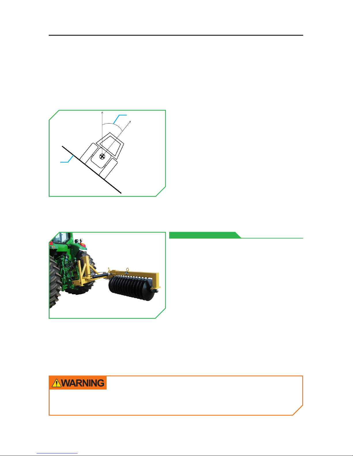
When transporting Diamond’s All
American Disc between operations,
make sure to protect it from collisions
and accidental damages by placing it in
the stowed position.
Failure to place the head in its stowed
position could result in
structural damage.
STOWED POSITION
•EXTREME CAUTION should be used
when operating on slopes(1) greater
than 25°(2). It is the operator’s
responsibility to properly counter-
balance the vehicle and machine to
prevent rollover.
Contact with the cutting discs while the All American Disc is in
operation can result in serious injury or death.
(2)
(1)
11
OPERATING THE ALL AMERICAN DISC
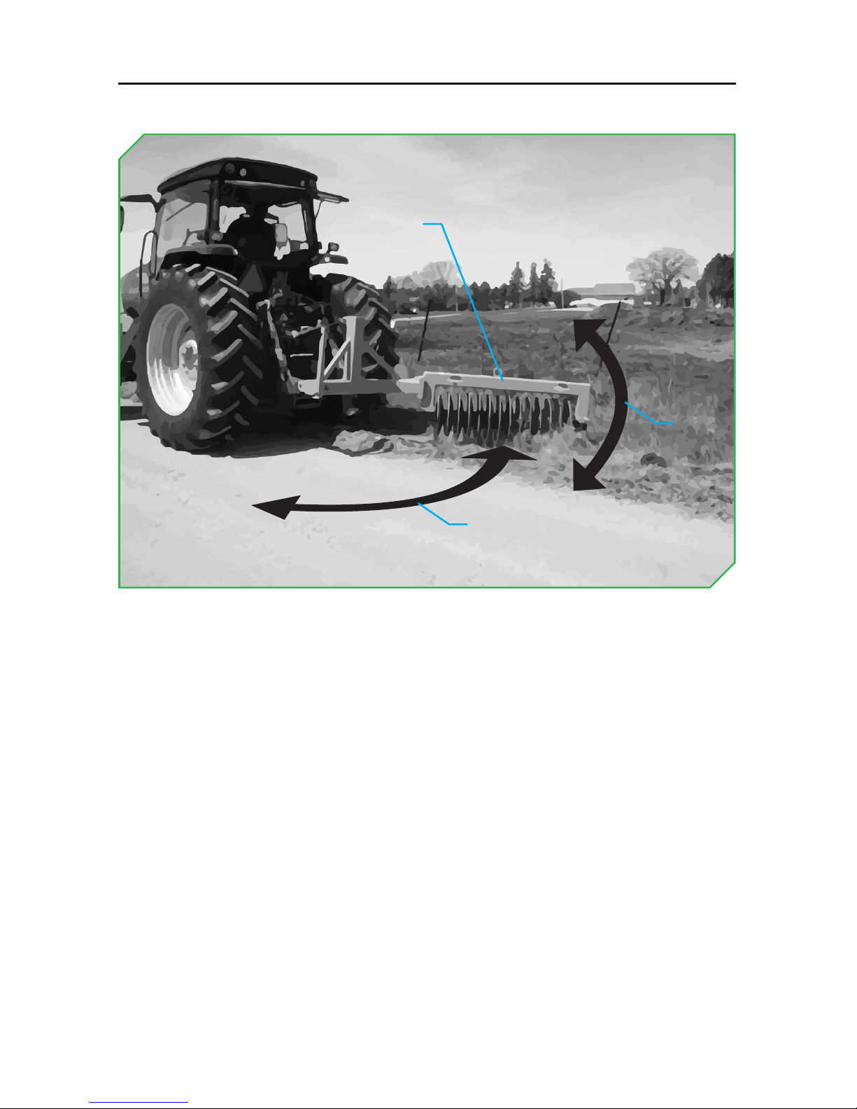
DISCING
CONTINUED ON NEXT PAGE
Use to reclaim road shoulder material.
•Start the tractor and raise the engine RPM’s to operating speed.
•Extend the optional swing cylinder (if present) until the disc housing(1) is
at full extension(2).
•Use the pitch cylinder to adjust the pitch(3) of the cutting discs.
◦The pitch of the cutting discs should allow the rearmost disc to enter
the soil before the lead disc when the discs are lowered into the soil.
◦DO NOT exceed a maximum of 15° difference in height between the
rearmost and lead cutting disc.
•Lower the cutting discs into the ground, but do not exceed 1” (25mm)
cut depth.
◦DO NOT cut sod with the lead blade! This indicates either there is
not enough pitch or the cutting depth is too deep, and will result
in peeling large clumps of sod; this is undesireable. Cutting is
accomplished with the other blades.
-Adjust your pitch as needed to prevent cutting with the lead disc.
(2)
(1)
(3)
12

•Begin discing the road shoulder at a steady pace (10MPH/16KMH)
maximum for gravel roads, less for hard surfaced roads.
◦Keeping the speed even and constant will allow the cutting discs to
feather the material evenly.
-It is recommended to allow the material to dry for a minimum of
two to three days, longer if there is precipitation, before discing.
Dry material grades easier than wet material.
-A roller will help on hard surfaced road shoulders. It is suggested
to disc, roll, grade, and then do a final roll for best results on hard
surfaced road shoulders.
-Always grade after the first pass of the discs.
DO NOT make multiple passes of the cutting discs and then
attempt to grade; there will be too much material to grade
effectively.
For more tips, visit us online at www.DiamondMowers.com
Lowering the cutting discs too deep into the soil can damage the road
shoulder, and can cause damage to the cutting discs, housing, and
hitch frame.
13
MAINTENANCE
Regular maintenance will make certain your unit stays productive and retains
a long operating life. The following chart represents the minimum intervals
recommended for inspection and maintenance.
MAINTENANCE INTERVALS
PROCEDURE 10 HOURS/DAILY
BEARINGS Inspect/Grease
HITCH FRAME Inspect
SWING CYLINDER (OPTIONAL) Grease
SWIVEL Grease
When replacing parts, use Genuine Diamond Parts. Guaranteed to ship within
72-hours of your order being placed, or the parts and shipping are free.
Call: 888-960-0361 or 605.977.3300 | Email: [email protected]
Order online: www.diamondmowers.com
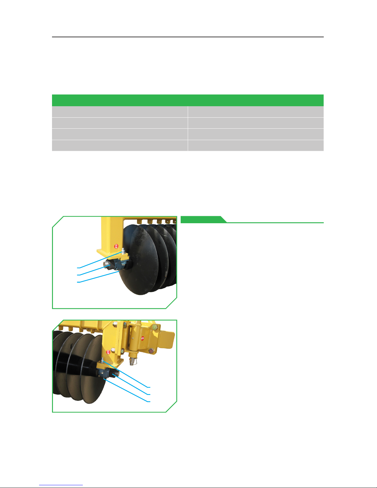
BEARINGS
•Inspect the hex nuts(1) on the disc
axle for loosening every 10 hours or
daily.
◦If hex nuts(1) are loose, torque
them with an impact wrench to
1500ft-lbs (2034Nm), or until
the discs are “ringing” from the
impact wrench.
•Inspect the mounting hardware(2)
for the axle bearings for loosening
every 10 hours or daily.
◦If mounting hardware(2) are loose,
torque them to
240ft-lbs (325Nm).
•Grease the zerks(3) on the axle
bearings until grease comes out
around the bearing axle bosses
every 10 hours or daily.
◦Use #2 lithium based grease.
(3)
(3)
(1)
(2)
(1)
(2)
14
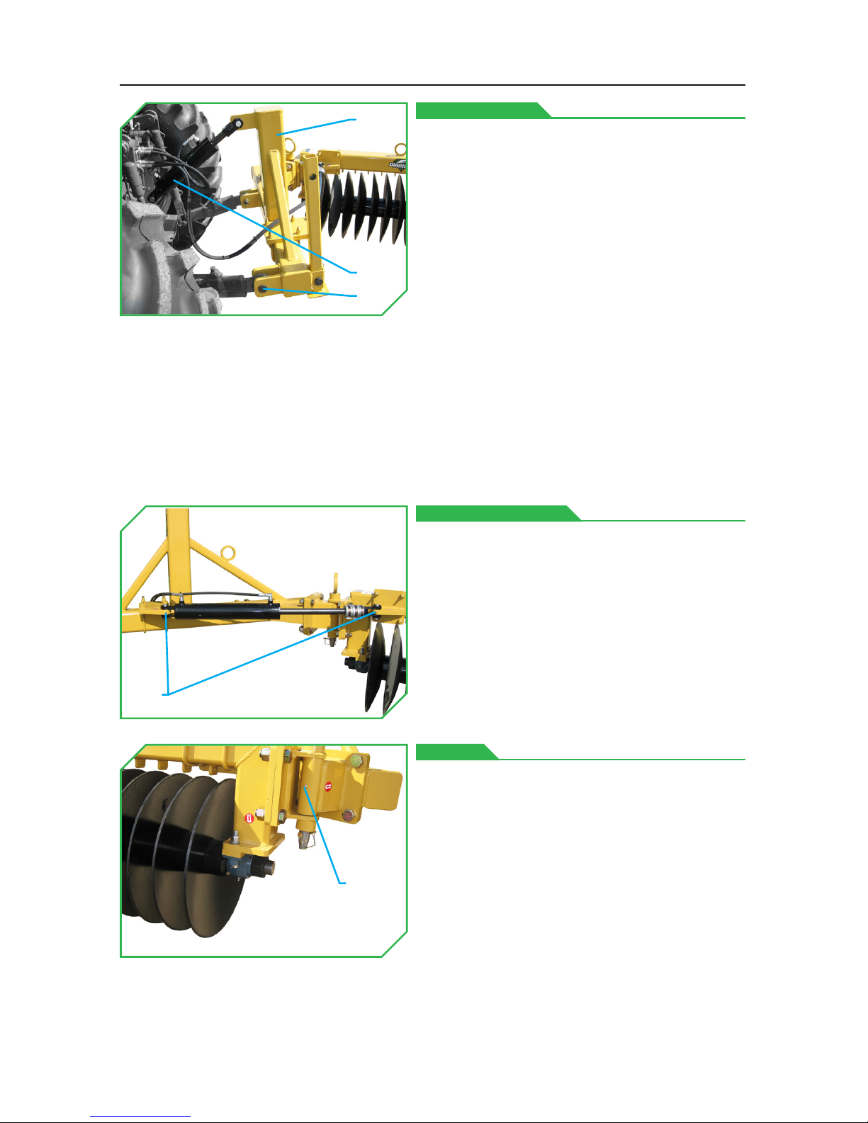
SWING CYLINDER
HITCH FRAME
SWIVEL
•Inspect the hitch frame(6) every 10
hours or daily before using
the implement.
Check the following:
◦Quick disconnect pins(4) and their
lynch pins.
◦Pitch cylinder(5), hardware, and
connections are in good repair.
◦Hitch frame(6) is in good repair.
-No stress cracks.
-No bent frame or components.
-No loosened hardware.
•OPTIONAL feature.
•Grease the zerks(7) every 10 hours or
daily on the swing cylinder anchors
until grease comes out around the
swing cylinder/anchor connections.
◦Use #2 lithium based grease.
•Grease the zerk(8) every 10 hours
or daily on the swivel until grease
comes out around the
swivel bosses.
◦Use #2 lithium based grease.
(4)
(7)
(8)
(6)
(5)
15

MAINTENANCE
(This Page Is Intentionally Left Blank)
16

TROUBLESHOOTING
For any questions, contact our Warranty / Service team at
888.960.0364 or 605.977.3300
PROBLEM POTENTIAL CAUSE SOLUTION
Disc Will Not Lift
Hydraulic cylinder
lift lines are not
connected
Connect the hydraulic cylinder lift
lines as instructed in this
operator’s manual.
Hydraulic cylinder or
hose leaks
Tighten hose connections.
Repair leaky cylinders and hoses.
Hydraulic cylinder
faulty
Repair or replace faulty cylinder.
Tractor 3-Point hitch
not working
Reference tractor operator manual for
troubleshooting the 3-Point
hitch system.
PROBLEM POTENTIAL CAUSE SOLUTION
Excessive
Vibration
Tractor 3-Point hitch
lower draft beam
float links set to
float (if equipped)
Place the tractor’s 3-Point hitch lower
draft beam float links to their
fixed position.
Loose hardware
Torque all hardware to the
recommended torque specifications
for that hardware.
Cutting blades are
employed too deep,
or at the wrong pitch
Verify the cutting blades are being
employed as recommended in the
operator’s manual.
Cutting assembly
is damaged or
unbalanced
Replace damaged blades.
Remove any debris (wire, etc.)
entangling the cutting
assembly.
17

(This Page Is Intentionally Left Blank)
TROUBLESHOOTING
18

PARTS BOOK
19
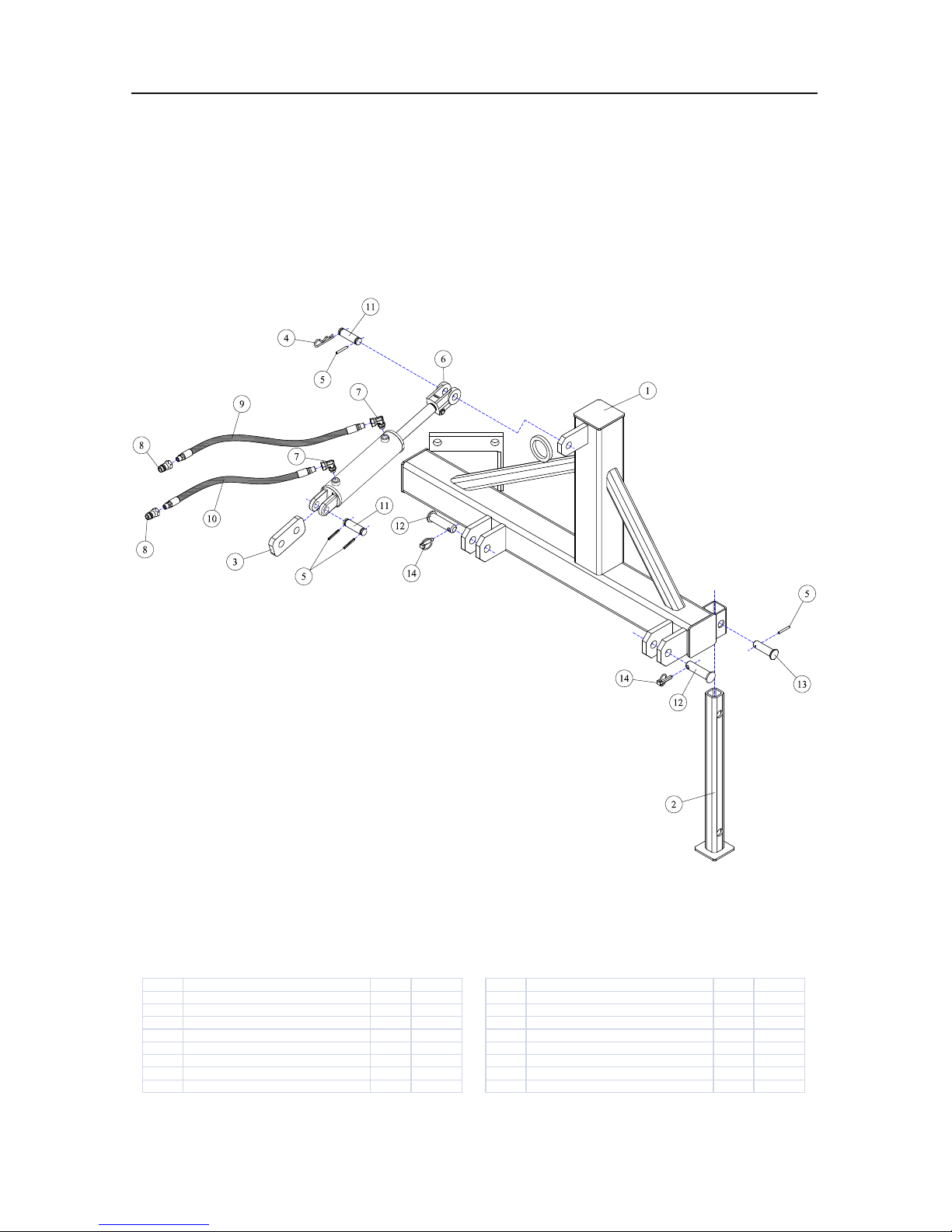
REF# PARTS DESCRIPTION REQ PART #
1 3-POINT FRA M E 1 1014
2 3-POINT STAND 1 1020
3 CENT ER LINK BRA CKET 1 1028
4 3/16 R-CLIP 1 11-2001
5 ROLLPIN 4 11-2005
6 3 X 10 W ELDED CYLINDER 1 14-0001
7 1/2ADJ-OR X 1/2FPX-90DEG 2 21-1119
REF# PARTS DESCRIPTION REQ PART #
8 1/2 MALE QUICK COUPLER 2 21-2119
9 HOSE 1/2 X 36 (1/2MP X 1/2MP) 1 21-2702
10 HOSE 1/2 X 24 (1/2MP X 1/2MP) 1 21-2706
11 CLEVIS PIN 2 27-0004
12 3-POINT PIN 2 27-0016
13 STAND PIN 1 27-0019
14 LYNCH PIN 2 27-1005
PARTS BOOK
HITCH FRAME, CATEGORY II 3-POINT
All American Disc
20
Table of contents


