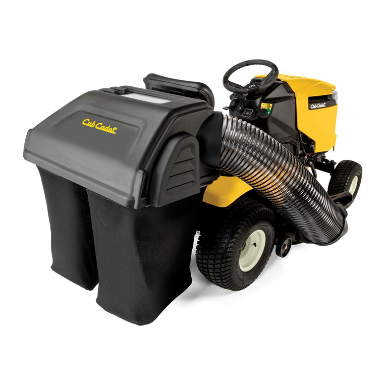
Cub Cadet 59A30047150 User manual

ASSEMBLY OPERATION MAINTENANCE
POWER ASSIST TRIPLE BAG
DESIGNED
TO FIT:
OPERATOR’S MANUAL
PRO-X
59A30047150
COLLECTION SYSTEM
21131509
2016-NEWER PRO Z 500, 700, 900 L&S
54” & 60” DECKS
MODEL #
MODEL YEAR:
ALTERNATE
MODEL #
Series:
*L MODELS: COLLECTION SYSTEM REQUIRES INSTALLATION*L MODELS: COLLECTION SYSTEM REQUIRES INSTALLATION
OF ADDED WEIGHT KIT P# 59B30037150 (A1149) FOR SAFE OPERATION!OF ADDED WEIGHT KIT P# 59B30037150 (A1149) FOR SAFE OPERATION!
*L MODELS: COLLECTION SYSTEM REQUIRES INSTALLATION
OF ADDED WEIGHT KIT P# 59B30037150 (A1149) FOR SAFE OPERATION!
MANUAL PART#: Q0507 Rev 3.1 - Oct 2020

2
GRASS COLLECTION SYSTEM
TABLE OF CONTENTS
SECTION PAGE
Safety - - - - - - - - - - - - - - - - - - - - - - - - - - - - - - 2
Safety Alert Symbols- - - - - - - - - - - - - - - - - - - - - - 3
Warranty - - - - - - - - - - - - - - - - - - - - - - - - - - - - - 4
I INTRODUCTION AND DESCRIPTION - - - - - - - - - - - - 5
1-1 Introduction - - - - - - - - - - - - - - - - - - - - - - - - - 5
1-2 Description - - - - - - - - - - - - - - - - - - - - - - - - - 5
II INSTALLATION FOR USE - - - - - - - - - - - - - - - - - - - - - 5
2-1 Preparation Of Mower - - - - - - - - - - - - - - - - - - 5
2-2 Mount Arm Preparation and Installation - - - - - - - 6
2-3 PTO Drive Assembly - - - - - - - - - - - - - - - - - - 7-8
2-4 Drive Assembly and Belt Installation - - - - - - - - - 9
2-5 Lower Mount Tube Installation - - - - - - - - - - - - - 10
2-6 Upper Frame Assembly Installation- - - - - - - - - - 10
2-7 Top Assembly to Upper Frame
Assembly Installation - - - - - - - - - - - - - - - - - - 10
2-8 Inlet Installation - - - - - - - - - - - - - - - - - - - - - - 10
2-9 Hinge Kit Installation - - - - - - - - - - - - - - - - - - - 10
2-10 Blower Cone Installation - - - - - - - - - - - - - - - - 11
2-11 Boot To Mower Deck Installation - - - - - - - - - - - 12
2-12 Length of Hose Adjustment - - - - - - - - - - - - - - 13
2-13 Upper Hose Installation - - - - - - - - - - - - - - - - 13
SECTION PAGE
2-14 Lower Hose To Blower Cone Installation- - - - - - 13
2-15 Lower Hose To Boot Installation - - - - - - - - - - - 13
2-16 Installation/Removal Of Collection Bags - - - - - - 14
2-17 Safety Interlock Harness Installation - - - - - - 15-17
Safety Interlock Harness Wiring Schematic - - - - - - - -17
2-18 Impeller Blade Removal/Replacement - - - - - - - 18
2-19 Even Bag Fill Adjustment - - - - - - - - - - - - - - - 19
Weight Kit Installation Instructions - - - - - - - - - - - - - 20
Exploded Views & Parts List - - - - - - - - - - - - - - - 21-30
Pack Drawing - - - - - - - - - - - - - - - - - - - - - - - - - - 31
Safety Decals - - - - - - - - - - - - - - - - - - - - - - - - - - 32
III OPERATING INSTRUCTIONS - - - - - - - - - - - - - - - - - - 33
3-1 General Safety - - - - - - - - - - - - - - - - - - - - - - - 33
3-2 Operation & Tips On Mowing - - - - - - - - - - - - - - 33
3-3 Disengagement Of The PTO Assembly - - - - - - - 33
3-4 Unloading The Collection System - - - - - - - - - - - 33
IV MAINTENANCE - - - - - - - - - - - - - - - - - - - - - - - - - - 33-34
4-1 Maintenance Checklist - - - - - - - - - - - - - - - - - - 33
4-2 Lubrication- - - - - - - - - - - - - - - - - - - - - - - - - - 34
V PARTS AND SERVICE - - - - - - - - - - - - - - - - - - - - - - - 34
5-1 Parts And Service Information - - - - - - - - - - - - - 34
Torque Specifications - - - - - - - - - - - - - - - - - - - - - 35
Troubleshooting - - - - - - - - - - - - - - - - - - - - - - - - - 36
Notes- - - - - - - - - - - - - - - - - - - - - - - - - - - - - - - - 37
SAFETY
1. Read the operator’s manual carefully and familiarize yourself with the proper use of your attachment. Do not allow
anyone who is not acquainted with the Safety Instructions to use your attachment.
2. Know the controls and how to stop them quickly. READ THE OPERATOR’S MANUAL!
3. Do not allow children to operate the machine. Do not allow adults to operate it without proper instruction.
4. Be especially watchful of children and pets entering into the area while operating.
5. Keep your eyes and mind on your machine while mowing or operating your attachment. Don’t let others distract
you.
6. Do not attempt to operate your machine when not in the driver’s seat.
7. Always shut off blades and engine when emptying the container.
8. Stop machine, shut off deck attachment, set parking brake, shut off engine and remove ignition key before
removing clogs, removing or replacing hose, boot, blower cone, or performing any maintenance.
9. Mow across the face of slopes (not less than 10 degrees); never up and down the face.
10. It is recommended that the container be emptied when half full while operating on slopes. Start mowing on slopes
when the container is empty.
11. Inspect your lawn and remove any foreign objects before mowing. Never deliberately run the mower across any
foreign object.
12. Wear hearing protection.
13. Wear eye protection to prevent debris from getting into your eyes.
2017 (v1.0)

3
SAFETY
WARNING! NEVER operate the mower unless the discharge guard and either the deflector assembly or
the vacuum collector adapter are fastened securely in place.
WARNING! Do not work around the mower deck boot or the blower area until you are certain that the mower
blades and the blower impeller have stopped rotating.
WARNING! To avoid serious injury, perform maintenance on the vacuum collector; ONLY AFTER
STOPPING THE MOWER’S ENGINE AND WAITING FOR ALL MOVING PARTS TO COME TO A
COMPLETE STOP. Set the parking brake. Always remove the ignition key before beginning maintenance.
WARNING! For your own personal safety, ALWAYS mow ACROSS the face of slopes and
NEVER UP and DOWN the face. NEVER attempt to mow excessively steep slopes, and use
caution when turning on any slope.
Safety Alert Symbol
This Safety Alert Symbol means: “ATTENTION! BECOME
ALERT! YOUR SAFETY IS INVOLVED!”
This symbol is used to call attention to safety precautions that
Should be followed by the operator to avoid accidents. When
you see this symbol, carefully read the message that follows
and heed its advice. Failure to comply with safety precautions
could result in death or serious bodily injury.
Safety Signs
The signal words DANGER, WARNING, and CAUTION are used on the equipment safety signs. These words
are intended to alert the viewer to the existence and the degree of hazard seriousness.
DANGER
!
CAUTION
This signal word indicates a potentially hazardous situation which, if not
avoided, will result in death or serious injury.
This signal word indicates a potentially hazardous situation which, if not
avoided, could result in death or serious injury.
It may also be used to alert against unsafe practices.
This signal word indicates a potentially hazardous situation exist which, if
not avoided, will result in minor or moderate injury.
It may also be used to alert against unsafe practices.
White letters on RED
Black letters on ORANGE
Black letters on YELLOW
WARNING
!
!
!
2017 (v1.0)

4
New PECO, Inc. extends the following warranties to the ORIGINAL PURCHASER of each New PECO, Inc. consumer product
purchased from one of our Dealers or directly from New PECO, Inc., subject to the following limitations:
A. ITEMS COVERED UNDER WARRANTY:
1. PRODUCT WARRANTY –
Any part or parts which are deemed defective in material or workmanship, as delivered to the
original purchaser, will either be repaired or replaced, as New PECO, Inc. elects, without charge for parts or labor, if
the defect appears within 12 months from the date of purchase of the product to the Original Purchaser.
2. PARTS REPLACED DURING WARRANTY –
Any New PECO, Inc. part which is furnished in performance of this warranty
and is defective in material or workmanship as delivered to the purchaser will be repaired or replaced, as New PECO,
Inc. elects, before the expiration of the original warranty period.
B. WARRANTY DISTINCTIONS:
1. RESIDENTIAL -
Products put to a personal use around a single household or residence are considered Residential.
Products designated as “Residential” are warrantied for 12 months from the date of purchase of the product, to the
ORIGINAL PURCHASER with proof of purchase, when used for or in residential applications.
2. COMMERCIAL –
Products put to any business use (agricultural, commercial or industrial) or used at multiple locations
are considered Commercial. Products designated as “Commercial” are warrantied for 12 months from the date of
purchase of the product, to the ORIGINAL PURCHASER with proof of purchase, when used for or in commercial
applications. Products designated as “Residential” are warrantied for 90 days from the date of purchase of the
product, to the ORIGINAL PURCHASER with proof of purchase, when used for or in Commercial applications.
3. RENTAL –
Products used for Rental or Lease Purposes are warrantied for 45 days from date of purchase of the product,
to the ORIGINAL PURCHASER with proof of purchase, when used for or in a rental business.
C. ITEMS NOT COVERED BY NEW PECO WARRANTY:
1. ENGINES & BATTERIES: Engines and Batteries attached to New PECO, Inc. products are covered under their respective
separate manufacturer warranties and those companies must be contacted directly to file a warranty claim. Briggs &
Stratton: https://www.briggsandstratton.com/na/en_us/support/warranty.html
2. UNAPPROVED ALTERATION OR MODIFICATION: All obligations of New PECO, Inc. under this warranty shall be
terminated if products are altered or modified in any way not approved by New PECO, Inc.
3. ACCIDENTS & NORMAL MAINTENANCE: This warranty covers ONLY manufacturers defective material and
workmanship. It does not cover depreciation or damage caused by normal wear & tear, accident, improper
maintenance, misuse or abuse of products. New PECO, Inc. products must be operated and maintained in
accordance with the instructions furnished in the manuals. The cost of normal maintenance and normal replacement
of service items such as belts, cutting blades, hoses, bags, etc., which are not defective shall be paid for by the
purchaser.
4. NO SERVICE CENTER WARRANTY: The selling Service Center/Dealer makes no warranty on his own on any item
warranted by New PECO, Inc. unless he delivers to purchaser a separate written warranty certificate specifically
warranting the item. The Service Center or Dealer has no authority to make any representation or promise on behalf
of New PECO, Inc. or to modify the terms of the original warranty in any way.
5. NO REPRESENTATIONS ADDITONAL WARRANTIES, DISCLAIMER: Neither New PECO, Inc. nor any company affiliated
with New PECO, Inc. makes any warranties, representations or promises as to the quality of performance of its
products other than those set forth herein. Except as described above, New PECO, Inc. makes no other warranties
AND SPECIFICALLY DISCLAIMS ANY AND ALL IMPLIED WARRANTIES OF FITNESS AND MERCHANTABILITY.
6. REMEDIED EXCLUSIVE: The only remedies the purchaser has in connection with the breach or performance of any
warranty on New PECO, Inc. consumer products are set forth above. In no event will New PECO, Inc. be liable for
special incidental or consequential damages.
Warranty service is available through your local authorized service dealer or distributor. If you do not know the dealer or
distributor in your area, search by your zip code on www.lawnvac.com
or contact our Sales Department at New PECO, Inc.
800-438-5823 or email [email protected].
PECO LIMITED WARRANTY FOR NEW PRODUCTS
2020 (v1.0)

5
Section I - INTRODUCTION &
DESCRIPTION
1-1 Introduction
Your grass collection system has been designed to give
you a low maintenance, simple, and effective way to
collect the grass clippings from your mower. This manual
is provided to give you the necessary instructions to
properly mount and operate the collection system on
your mower. Please read this manual thoroughly.
Understand what each control is for and how to use it.
Observe all safety decal precautions on the machine and
noted throughout the manual.
NOTE: All references made to right, left, front, rear, top
or bottom are as viewed from the normal operator’s
position on the mower.
1-2 Description
The grass collection system is designed for turf
maintenance where there is a need to collect the grass
clippings as the mower cuts the turf. It is also used for
picking up leaves in pre-season and post-season clean-
up. The blower, mounted on the right side of the unit,
uses a belt and gearbox system from the engine PTO
shaft. Drive train protection comes through belt slippage.
The blower draws grass clippings from the discharge
area of the cutting deck back to the (2) - 4 cubic foot
collection bags P#(G0013-L) at the rear portion of the
mower frame. The operator can engage the blower with
a toggle switch mounted on the control panel to the right
of the operator. Once the bags are full with clippings,
they can be easily released for dumping.
Section II - INSTALLATION FOR USE
L Models: Collection system requires installation of
added weight kit 59B30037150 (A1149) for safe
operation! S Models do not require a weight kit.
Collection System May Require
Dealer Installation!
Please refer to Page 15 for further details.
2-1 Preparation Of Mower
From the underside of the engine, disconnect the wiring
harness attached to the electric clutch. Remove the bolt
and electric clutch from the mower. Refer to Figure 2-1a.
Remove the D-drive spacer using an arbor press or
equivalent. On removal, adjacent bearing OUTER race
must be supported or bearing damage may occur. Refer
to Figure 2-1b.
The Engine Pulley Bushing #18 P#(S0210) may need to
be installed using an arbor press or equivalent. If
pressed, opposite bearing inner race must be supported
or bearing damage may occur. Refer to Figure 2-1c.
Fasten the A-Section Pulley P#(M0309) to the Pulley
Bushing and electric clutch assembly using (1) 7/16”
Double Indented Washer P#(K0278), (1) 7/16” Hi-Collar
Lock Washer P#( ) and (1) 7/16”-20 x 3-3/4” K0140
HHCS P#(K0350) as shown in Figure 2-1d. Torque the
bolt to 55 ft-lbs. Re-connect the wiring harness to the
electric clutch.
PRESS
PRESS
Engine Pulley Installation
Figure 2-1b
Figure 2-1c
Remove Bolt D-Drive Spacer
Electric Clutch
A-Section
Pulley
Hex Bolt Lock Washer
Engine Pulley
Number Is
Stamped On
The Pulley
Bushing
Double
Indented
Washer
Figure 2-1a
Figure 2-1d

6
Figure 2-2a
Figure 2-2b
Remove
3/8”-16 x 1” Carriage Bolt
3/8”-16 x 1-1/4” Carriage Bolt
3/8”-16 x 1-1/2”
Carriage Bolt
2-2 Mount Arm Preparation and Installation
Remove the (4) 3/8”-16 x 1-1/4” existing Carriage Bolts and (4) 3/8”-16 Ny-Flange Lock Nuts from the right-rear of the
mower and discard. Refer to Figure 2-2a.
First, loosely attach the Mount Arm Brace P#(B0953) to the Mount Arm Assy. P#(A2071) using (2) 3/8”-16 x 1”
Carriage Bolts P#(K1182) and (2) 3/8”-16 Ny-Flange Lock Nuts P#(K2038). Next, attach both parts to the right rear
of the mower using (4) 3/8”-16 x 1-1/2” Carriage Bolts P#(K1337), (2) 3/8”-16 x 1-1/4” Carriage Bolts P#(K1183) and
(6) 3/8”-16 Ny-Flange Lock Nuts P#(K2038). Once in place tighten all bolts to suggested torque. Refer to Figure 2-
2b.

7
Notice Marked Holes Below;
(Use corresponding holes with type of
mower that is being fitted up)
T = Pro Z 500, 700 & 900 Series Mounting Hole
P = Pro Z 100 Series Mounting Hole
BELT GUARD ASSY. HOLES
Item # Part # Desc. Qty.
1 K1010 1/4"-20 x 5/8" Carriage Bolt 2
2 K2014 1/4"-20 Ny-Flange Lock Nut 2
1
1
Belt Guard
Drive Assembly
2
2
Figure 2-3a
2-3 PTO Drive Assembly
Once the Mount Arm Assembly P#(A2071) is installed and secured to the mower, assemble the Drive Assembly
P#(A2072), Belt Guard Assembly P#(A2069_03), Idler Mount Assembly P#(A2067_03) & Belt Guard Gusset
P#(B1026).
First, attach the Belt Guard Assembly P#(A2069_03) to the Drive Assembly P#(A2072) using (2) 1/4”-20 x 5/8”
Carriage Bolts P#(K1010) and (2) 1/4”-20 Ny-Flange Lock Nuts P#(K2014). Refer to Figure 2-3a. Leave Bolts
Loose.

8
8
Figure 2-3b
Figure 2-3d
Figure 2-3c
A
B
Idler Mount
Assembly Drive
Assembly
Next, secure the Idler Mount Assembly P#(A2067_03) to the Belt Guard Assembly P#(A2069_03) using (2) 3/8”-16 x
1” Carriage Bolts P#(K1182) and (2) 3/8”-16 Ny-Flange Lock Nuts P#(K2038).
Then, secure the Belt Guard Gusset P#(B1026) to the Belt Guard Assembly using (2) 3/8”-16 x 1” Carriage Bolts
P#(K1182) & (2) 3/8”-16 Ny-Flange Lock Nuts P#(K2038). Refer to Figure 2-3c & 2-3d.
Finally, tighten all bolts.
3/8”-16 Ny-Flange
Lock Nut
3/8”-16 x 1”
Carriage Bolt
3/8”-16 Ny-Flange Lock Nut
3/8”-16 x 1” HHCS
Belt
Guard
Assembly
Belt Guard
Assembly
Idler Mount
Assembly
Idler Mount
Assembly
Belt
Guard
Gusset
3/8”-16 Ny-Flange
Lock Nut
3/8”-16 Ny-Flange
Lock Nut
3/8”-16 x 1” Carriage Bolt
3/8”-16 x 1”
Carriage Bolt
3/8”-16 x 1” Carriage Bolt
3/8”-16 Ny-Flange
Lock Nut
3/8”-16
Ny-Flange
Lock Nut
3/8”-16 x 1” Carriage Bolt
2-3 PTO Drive Assembly (Continued)
Attach the Idler Mount Assembly P#(A2067_03) to the Drive Assembly using (1) 3/8”-16 x 1” HHCS (A) P#(K1191), (1)
3/8”-16 x 1” Carriage Bolt (B) P#(K1182) and (2) 3/8”-16 Ny-Flange Lock Nuts P#(K2038). Refer to Figure 2-3b.
Leave Bolts Loose (Note: Orientation of bolts A & B).

9
Drive Assembly
Mount Arm Assembly
Knob Plunger Pin
Lock Handle
Belt Path
Engine Drive Pulley
V-Idler
Pulley
Drive Assembly Pulley
Flat Idler Pulley
Insert Screw
Driver Here
2-4 Drive Assembly and Belt Installation
(Note: It is recommended that someone assist during this step.)
Insert the Drive Assembly into the receiver tube on the Mount Arm Assembly until the Knob Plunger Pin engages.
Once in place, turn Lock Handle clockwise until tight. Next, feed the AK83 Belt P#(M0315) between the Belt Guard
and the Idler Mount Assembly. Place belt around the Engine Drive Pulley on the underside of the mower. While one
person inserts a screw driver (or similar tool) into the Idler Mount Assembly and rotates lever arm clockwise, enough
to relieve all tension from belt, place belt around the Drive Assembly Pulley. Once the belt is in position, carefully
release the tension to tighten belt.
Refer to the images below.

10
(2) 5/16”-18 x 2-1/2” HHCS
(2) 5/16”-18 Locknuts
Top Assembly
Figure 2-7
Nylon
Flange
Locknut
Hex
Bolt
Inlet
Hair Pin
Clip
Clevis
Pin
K0506 B0884
K2516
K0042
S0006
K0505
K0042
K1156
Figure 2-9
Figure 2-5
Rubber
Dust Guard
Trailer Hitch Plate
10
2-5 Lower Mount Tube Installation
Secure the (2) Lower Mount Tubes P#(B0752) to the
rear frame using (2) 5/16”-18 U-bolts P#(K1098) and (4)
5/16”-18 Ny-Flange Lock Nuts P#(K2516) PER TUBE.
Refer to Figure 2-5. Note: Bottom of Tubes should rest
on the top edge of the Trailer Hitch Plate.
2-6 Upper Frame Assembly
Installation
Lift the Upper Frame Assembly P#(A2068) into position,
and slide onto the Lower Mount Tubes as shown in
Figure 2-7 and secure with (2) 1/2” x 2-1/4” Clevis Pins
P#(K0133) and (2) Hair Pin Clips P#(K0088). Note: It is
recommended that someone assist you when installing
the upper frame assembly.
2-7 Top Assembly To Upper Frame
Assembly Installation
Position the Top Assembly P#(A2081) above the Upper
Frame Assembly with the Rubber Dust Guard positioned
towards the seat as shown in Figure 2-7. Fasten the Top
Assembly to the Upper Frame Assembly using (2) 5/16”-
18 x 2-1/2” HHCS P#(K0125) and (2) 5/16”-18 Ny-
Flange Lock Nuts P#(K2516). Leave the lock nuts
slightly loose, to allow the top assembly to open and
close easily. Refer to Figure 2-7 for hardware location.
2-8 Inlet Installation
Insert the Inlet P#(A2074) into the hole on the Top
Assembly from the inside and then snap the Inlet into
place. The Inlet should pivot freely about the hole.
2-9 Hinge Kit Assembly Installation
Assemble the Hinge Kit as shown in Figure 2-9, using
(1) Latch Plate P#(B0884), (1) 5/16”-18 x 1-1/4” HHCS
P#(K1156), (1) 5/16”-18 Ny-Flange Lock Nut P#(K2516),
(3) 5/16” Flat Washers P#(K0042), (1) Latch Spacer
P#(S0006), (2) Extra Heavy 5/16” Fender Washers
P#(K0505) and (1) 5/16”-18 Lock Nut P#(K0506). Leave
the nuts loose enough to allow fluid movement of the top
when opening and closing. When opened, the top should
rest in the Latch Plate Slot.

11
Figure 2-10b
Threaded
Boss
Blower
Cone Tab
Figure 2-10c (1st) Tighten
Bolt
(2nd) Tighten
Jam Nut
Figure 2-10d
Blower
Cone
Figure 2-10a
Thread (1) Jam Nut
Onto Each 5/16”-18 Bolt
2-10 Blower Cone Installation
Thread (1) 5/16”-18 jam nut P#(K0120) onto each end of (2) 5/16”-18 x 2-1/2” HHCS P#(K0125) as shown in Figure
2-10a.
Now partially thread (1) bolt into each of the two threaded bosses located on the blower housing. Place 8” Blower
Cone P#(E6009) so the two tabs line up with the bolts and tighten completely as shown in Figure 2-10b.
Once the (2) bolts are tight, tighten the jam nuts against the threaded boss as shown in Figure 2-10c.
Refer to Figure 2-10d for proper blower cone installation reference.

12
12
Note: Deflector not shown for clarity but must be installed during normal operation.
Figure 2-12b
Figure 2-12a
2-11 Boot To Mower Deck Installation
NOTE: The Boot Kit Assembly is designed to fit the 54”
and 60” deck. To ensure a snug fit between the boot and
the mower deck, follow the instructions in this step
thoroughly, and remove and tighten all hardware in the
sequence specified.
According to deck size, align marked holes and Boot
holes. Secure the Boot Mounting Assembly P#(A2045)
to the Aluminum Boot P#(E0028A) using (2) 3/8”-16 x 1”
Carriage Bolts P#(K1182) and (2) 3/8”-16 Ny-Flange
Lock Nuts P#(K2038). Insert the Carriage Bolts from the
inside of the Boot so the threads are on the outside of
the Boot (Figure 2-12a). This will prevent grass clippings
from collecting on the bolt threads. Leave bolts loose for
alignment once installed on mower.
After removing only the Wing Knobs, align the threaded
mount posts on the Boot Mounting Assembly with the
mounting holes located above the mowers discharge
chute and insert into the mounting holes. Secure with the
(2) Wing Knobs P#(J0018). Press Boot against
discharge chute, to ensure a snug fit and tighten the two
nuts on top of the boot. Refer to Figure 2-12b.

13
Boot
Inlet
Hose
Clamp
Upper
Hose
Blower
Outlet
Blower
Cone
Lower
Hose
Hose
Clamps
Figure 2-13
Snap
Fastener
2-12 Length Of Hose Adjustment
The hoses in the following steps must be cut to fit your
machine. Do not cut the hoses until you have tried to fit
them on your machine. Remember that the hoses need
to be long enough to allow for the opening and closing of
the collection system as well as allowing ample clamping
surface between each component.
2-13 Upper Hose Installation
Slide a pre-assembled Hose Clamp P#(J0070) over one
end of the 7” Upper Hose. Secure this end of the 7”
Upper Hose to the Blower Outlet. See Figure below for
details. Secure opposite end of the 7” Upper Hose to the
Inlet. Make sure both ends are securely fastened by
tightening the Hose Clamp and rotating the Inlet Snap
Fastener towards the hose to lock in place.
2-14 Lower Hose To Blower Cone
Installation
Slide a pre-assembled Hose Clamp P#(J0080) over both
ends of the Lower Hose. Secure one end of the Lower
Hose to the Blower Cone and fasten by tightening the
Hose Clamp.
2-15 Lower Hose To Boot Installation
Take the unattached end of the Lower Hose and secure
it to the circular end of the Boot and fasten by tightening
the Hose Clamp (Figure 2-13). Tip: Before securing
Hose Clamp fully, rotate Lower Hose counter-clockwise
(away from yourself) approximately 1” to aid in retaining
Boot to mower deck.

14
14
2-16 Installation/Removal Of
Collection Bags
IMPORTANT!
To prevent bag wear, install (1) black rubber end cap
P#(F0010), as shown in Figure 2-16a, on each bag ring
after rotating bag 360°.
To complete the bag installation, place the seam
openings of the bag and the bag ring openings together.
Place the rubber bag ring connector on both ends of the
bag ring and turn the bag one half turn (180 ) so the
rubber end cap is located opposite to the opening in the
bag (Figure 2-16b). Do this for each bag.
Install the completed assemblies onto the support frame
and close the plastic top. Fasten the draw-latches to
hold the plastic top closed (Figure 2-16c).
Black Rubber
Connector
Bag Ring
Bag
Bag Opening
Bag Ring Rubber End
Cap Opposite
of Bag Opening
Figure 2-16a
Figure 2-16b
To empty the bag, first unlatch and lift top, next remove
the bag and bag ring by sliding rearward, then grasp the
handle on the bottom of the bag, and lastly turn it upside
down to empty the collected debris (Figure 2-16d).
Repeat for the other bags. Reinstall all bags, line with
plastic bags if desired, close the plastic top and reattach
the draw latches.
Plastic lawn and leaf bags, 33 gallon size, may be used
inside the cloth bags. Be sure to leave enough plastic
bag hanging over the frame so the plastic bags can be
twist tied before emptying (Figure 2-16e).
Figure 2-16e
Grasp Bag
Here
Figure 2-16d
Plastic Bag
Cloth Bag
Plastic Top
Fasten Draw-
Latch Here &
Opposite Side
For Proper Unit
Transportation
Completed Bag
Installed
Figure 16-c

15
WARNING
!
To Prevent Serious Injury-
Proper Installation Of Safety Interlock Harness
Is Mandatory. Please Check That All Interlock
Points Work Correctly Once Installed.
D
Figure 2-17a
(E) PTO Switch
(D) Drive Clutch Connector
(A)
Connection
Point
(B & C)
Interconnect
2-17 Safety Interlock Harness
Installation
Collection System May Require Dealer Installation!
Before installing, please verify the presence of an
auxiliary 5-way female connector in the mower’s
electrical harness. The connector is located underneath
the operator’s seat in between the two hydraulic pump
cooling fans.
Connect (A) the Delphi 5-way Male Connector, on the
harness, to the connection point under the seat and
between the two cooling fans. Next, on the left side of
the engine locate and separate the engine harness from
the mower’s main harness. Connect (B) to the engine
side connector and (C) to the main harness connector.
Refer to Figure 2-17a & 2-17b.
Route the Drive Clutch Connector (D) around the front
side of the engine, between the ROPS and gas tank and
through the opening in the rear bumper connecting to
the quick connect plug located on the PTO Drive.
Before routing the PTO Switch (E), locate and remove
knock out on the mower’s control panel. The control
panel is easily accessed by removing the (9) hex head
screws around the outside of the control panel housing.
Route (E) through the frame and up to the underside of
the control panel. Insert switch into the hole, previously
knocked out, and snap the provided retaining plate to the
underside of the control panel. The retainer plate (F)
should be seated fully over the snap wings of switch
from the underside of the panel after the switch is
installed. Connect the switch to connector and reattach
control panel.
Use the zip ties that are provided to secure in place.

16
Figure 2-17b
D
Drive
Clutch
Connector
E
Bagger
PTO Switch
A
5-Way Male
Connector
C
Main Harness
Engine Connector
B
Engine Side
Engine Connector
F
Retainer Plate
16
2-17 Safety Interlock Wiring Harness Installation (Continued)

17
P0274 Rev. 1
2-17 Safety Interlock Harness Installation (Continued)
Wiring Schematic

18
18
2
34
5
1
Figure 2-18
2-18 Impeller Blade Removal/Replacement
To Remove: First remove the 5/16”-24 x 1-1/2” HHCS GR8 P#(K1465) (#1), Taper-Lock Bushing Washer P#(K0284)
(#3) and (2) Spacer Bushings P#(S0159) (#4) from the Taper-Lock Bushing P#(S0157) (#5). See Figure 2-18. Next
remove the (2) 1/4”-20 x 1” HHCS (#2) and place them into the threaded holes of the Taper-Lock Bushing (#5).
Gradually thread each bolt evenly into the Taper-Lock Bushing, forcing the Impeller Blade to break-away from the
Taper-Lock Bushing. If the Impeller Blade will not move, carefully hit the base of the Impeller Blade, between each
vein, with a hammer, then try again.
To Replace: Place Impeller Blade over the engine shaft. Slide the Taper-Lock Bushing P#(S0157) (#5) on to the
engine shaft and into the Impeller Blade, aligning the non-threaded holes of the Taper-Lock Bushing to the threaded
holes of the Impeller Blade. Fasten by using (2) 1/4”-20 x 1” HHCS (#2), (2) Spacer Bushing P#(S0159) (#4) (1)
Taper-Lock Bushing Washer P#(K0284) (#3), and (1) 5/16”-24 x 1-1/2” HHCS P#(K1465) (#1). Torque to the proper
specifications in the torque chart within the last pages of this manual. Next, rotate the Impeller Blade to ensure that
the Blade is clear of contact on all sides of the Blower Housing.

19
Flap Can Be Adjusted Up/Down
Depending On Mowing Conditions.
Adjust Flap Up To Allow More Dense
Material To Reach Left Bag. Adjust
Flap Down To Allow Less Dense
Material To Reach The Right Bag.
Once Adjusted Properly, All Bags
Should Fill Evenly, But May Require
Further Adjusting When Mowing
Conditions Change.
2-19 Even Bag Fill Adjustment

20
Cub Cadet Tank LZ & L Models - Installing a weight kit
is mandatory for safe operation of the collection system.
SZ & S Models do not require a weight kit.
Completely thread (2) 3/8”-16 flange nuts P#(K1215)
onto (1) 3/8”-16 U-bolt P#(K0407). Repeat process again
to create two sets. Secure each U-Bolt, w/ attached
flange nuts, to the weight bracket P#(B0703) using (2)
3/8”-16 nylon flange locknuts P#(K2038) as shown in
Figure 1-1.
Remove the mower’s pulley access cover shown in
Figure 1-2.
Insert the weight bracket assembly into the recess as
shown in Figure 1-3. Align the weight bracket’s mounting
holes to the mower’s frame and secure using (2) 5/16”-
18 x 3/4” Carriage Bolts P#(K1142) and (2) 5/16”-18
nylon flange locknuts P#(K2516). Insert the bolts from
the bottom of the weight bracket so that the nuts fasten
to the top of the bracket as shown in to Figure 1-3.
One at a time, add (1) large weight bar P#(B0704) to the
weight bracket, then (2) small weight bars P#(B0741).
Refer to Figure 1-4.
Add the remaining (2) large weight bars P#(B0704) to
the weight bracket. Secure the weights to the weight
bracket with (1) weight strap P#(B0719) and (2) 1/4”-20
self-tapping screws P#(K0353). Refer to Figure 1-5.
Replace mower’s pulley access cover when completed.
59B30037150 (A1149) -59B30037150 (A1149) -
Weight Kit Installation InstructionsWeight Kit Installation Instructions
59B30037150 (A1149) -
Weight Kit Installation Instructions
Figure 1-1 (2) U-Bolts
w/ Flange Nuts
Weight
Bracket
(2) 3/8”-16 Nylon
Flange Locknuts
per U-Bolt
Remove Pulley
Access Cover
Figure 1-3
(2) 5/16”-18 x 3/4”
Carriage Bolts
(2) 5/16”-18 Nylon
Flange Lock Nuts
Figure 1-4
(2) Small
Weight Bars
(1) Large
Weight Bar
Weight
Strap
1/4”-20
Self-Tapping
Screw
Figure 1-5
(2) Large
Weight Bars
Figure 1-2
20
This manual suits for next models
1
Table of contents
Other Cub Cadet Tractor Accessories manuals
Popular Tractor Accessories manuals by other brands

MTD
MTD 19A30020OEM installation manual

HAUL MASTER
HAUL MASTER HAULMASTER 97214 Owner's manual & safety instructions

Nordic Plow
Nordic Plow ZERO TURN 49 MOUNTING KIT Mounting instructions

METAL PLESS
METAL PLESS PLOWMAXX PLLT 04.527-8.5 owner's manual

Tiger
Tiger JD6175R Mounting and operating instructions

Grouser Products
Grouser Products Ag Pro Classic Owner's manual & parts book