DIAQUIP QHS-400 User manual

QHS-400 ELECTRIC HANDSAW
OPERATORS MANUAL
21
20
22
OPTION
North America: 20 A,
/02 WWW.DIAQUIP.CO.UK WWW.DIAQUIP.CO.UK /03
TECHNICAL DATA
Power Input
Voltage
Rated speed/ min-1
Blade Diameter
Arbor
North America: 115V~60Hz, Other Regions: See Machine Nameplate
n=3900 min-1
400mm (16”)
25.4 (1”)
Max. Cutting Depth
Weight
Dimensions
Vibrations (excl. blade)
Sound Power Level
No Load Speeds
150mm (6”)
9.1kg, 10kg with guide rollers
735mm x 259mm x 364mm
3.0 m/s2- rear handle 3.9 m/s2- front handle
116.0dB (A) - (LWA) 105.0dB (A) - (LPA)
3900min-1
GENERAL SAFETY INSTRUCTIONS
WARNING! Read all safety warnings and all instructions. Failure to follow the
warningsandinstructionsmayresultinelectricshock,reand/orseriousinjury.
ORIGINAL INSTRUCTIONS: For your personal safety, read and understand before using.
Save these instructions for future reference
Save all warnings and instructions for future reference.
The term “power tool” in the warnings refers to your mains operated (corded) power tool or
battery-operated (cordless) power tool.
General Power Tool Safety Warnings - Work Area Safety
a. Keep work area clean and well lit. Cluttered or dark areas invite accidents.
b. Do not operate power tools in explosive atmospheres, such as in the presence
ofammableliquids,gasesordust.Power tools create sparks which may ignite
the dust or fumes.
c. Keep children and bystanders away while operating a power tool. Distractions
can cause you to lose control.
General Power Tool Safety Warnings - Electrical Safety
a. Power tool plugs must match the outlet. Never modify the plug in any way. Do
not use any adapter plugs with earthed (grounded) power tools. Unmodied
plugs and matching outlets will reduce risk of electric shock.
b. Avoid body contact with earthed or grounded surfaces such as pipes,
radiators, ranges and refrigerators. There is an increased risk of electric shock if
your body is earthed or grounded.
c. Do not expose power tools to rain or wet conditions. Water entering a power tool
will increase the risk of electric shock.
d. Do not abuse the cord. Never use the cord for carrying, pulling or unplugging
the power tool. Keep cord away from heat, oil, sharp edges or moving parts.
Damaged or entangled cords increase the risk of electric shock.
e. When operating a power tool outdoors, use an extension cord suitable for
outdoor use. Use of a cord suitable for outdoor use reduces the risk of electric
shock.
f. If operating a power tool in a damp location is unavoidable, use a PRCD or
ground fault circuit interrupter (GFCI) protected supply.
Use of a GFCI reduces the risk of electric shock.
Other Regions
110-120V:2300W certicate (3000W actual)
220-240V: 2700W certicate (3200W actual)
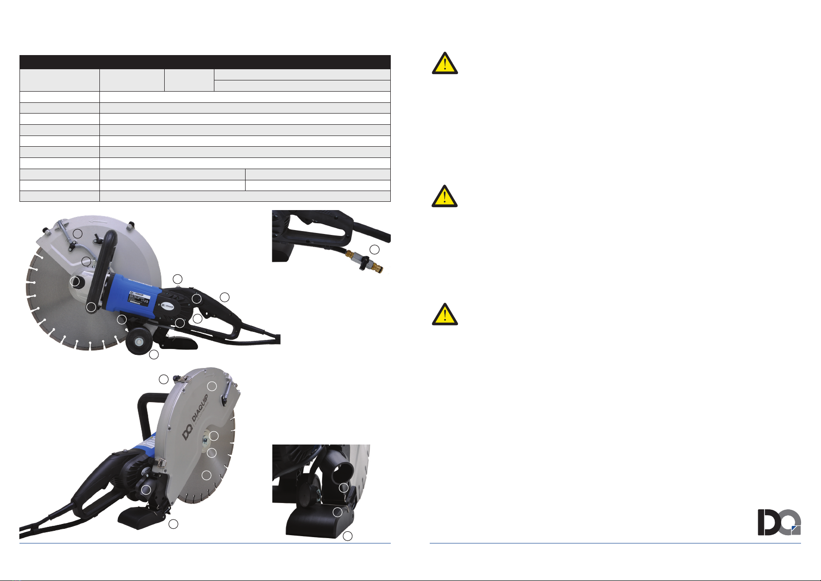
12
1. Water Feed Nozzle
2. Blade Guard Locking Lever
3. Load Warning Lamp
4. Release Button
5. Main Handle
6. Trigger Switch
7. Brush Cover
8. Guide Roller Assembly
9. Buttery Bolt
10. Side Handle
11. Arbor Lock Button
12. Water Feed Valve
13. Toggle Latches
14. Blade Guard
15. Arbor Bolt
16. Outer Flange
17. 400mmØ Diamond Blade
18. Blade Guard Brush
19. Vacuum Port
20. Splash Guard
21. Male Clip
22. Female Clip
1
2
3
45
6
7
8
9
10
11
13
14
15
16
17
18
19
TECHNICAL DATA

/04 WWW.DIAQUIP.CO.UK WWW.DIAQUIP.CO.UK /05
GENERAL SAFETY INSTRUCTIONS
General Power Tool Safety Warnings - Personal Safety
a. Stay alert, watch what you are doing and use common sense when operating a
powertool.Donotuseapowertoolwhileyouaretiredorundertheinuence
of drugs, alcohol or medication. A moment of inattention while operating power
tools may result in serious personal injury.
b.Usepersonalprotectiveequipment.Alwaysweareyeprotection.Protective
equipment such as dust mask, non-skid safety shoes, hard hat, or hearing protection
used for appropriate conditions will reduce personal injuries.
c. Prevent unintentional starting. Ensure the switch is in the off-position before
connectingtopowersourceand/orbatterypack,pickinguporcarryingthe
tool. Carrying power tools with your nger on the switch or energising power tools
that have the switch on invites accidents.
d.Removeanyadjustingkeyorwrenchbeforeturningthepowertoolon.A
wrench or a key left attached to a rotating part of the power tool may result in
personal injury.
e. Do not overreach. Keep proper footing and balance at all times. This enables
better control of the power tool in unexpected situations.
f. Dressproperly.Donotwearlooseclothingorjewellery.Keepyourhair,
clothing and gloves away from moving parts. Loose clothes, jewellery or long
hair can be caught in moving parts.
g. If devices are provided for the connection of dust extraction and collection
facilities, ensure these are connected and properly used. Use of dust collection
can reduce dust-related hazards.
GENERAL SAFETY INSTRUCTIONS
General Power Tool Safety Warnings -
Power Tool Use And Care
a. Do not force the power tool. Use the correct power tool for your application.
The correct power tool will do the job better and safer at the rate for which it was
designed.
b. Do not use the power tool if the switch does not turn it on and off. Any power
tool that cannot be controlled with the switch is dangerous and must be repaired.
c.Disconnecttheplugfromthepowersourceand/orthebatterypackfromthe
powertoolbeforemakinganyadjustments,changingaccessories,orstoring
power tools. Such preventive safety measures reduce the risk of starting the power
tool accidentally.
d. Store idle power tools out of the reach of children and do not allow persons
unfamiliar with the power tool or these instructions to operate the power tool.
Power tools are dangerous in the hands of untrained users.
e. Maintain power tools. Check for misalignment or binding of moving parts,
breakage of parts and any other condition that may affect the power tool’s
operation. If damaged, have the power tool repaired before use. Many accidents
are caused by poorly maintained power tools.
f Keep cutting tools sharp and clean. Properly maintained cutting tools with sharp
cutting edges are less likely to bind and are easier to control.
g. Use the power tool, accessories and tool bits etc., in accordance with these
instructions, taking into account the working conditions and the work to be
performed. Use of the power tool for operations different from those intended could
result in a hazardous situation.

/06 WWW.DIAQUIP.CO.UK WWW.DIAQUIP.CO.UK /07
GENERAL SAFETY INSTRUCTIONS
General Power Tool Safety Warnings - Service
a.Haveyourpowertoolservicedbyaqualiedrepairpersonusingonlyidentical
replacement parts. This will ensure that the safety of the power tool is maintained.
Symbols used in this manual
V…….......Volts
A…….......Amperes
Hz…….....Hertz
W……......Watt
~………....Alternating current
no……….. Rated speed
min-1….....Revolutions or reciprocation per minute
.....Warning of general danger
.....Read these instructions
.....Always wear eye protection
.....Always wear a dust mask.
.....Always wear hearing protection
.....Wear safety-approved hard hat
.....DANGER! Keep hands away from cutting area and the blade.
Do not dispose of electric tools, accessories and
packaging together with household waste material
SAFETY INSTRUCTIONS FOR
CUTTING-OFF OPERATIONS
Cut-off machine safety warnings
a. The guard provided with the tool must be securely attached to the power tool
and positioned for maximum safety, so the least amount of wheel is exposed
towards the operator. Position yourself and bystanders away from the plane
of the rotating wheel. The guard helps to protect the operator from broken wheel
fragments and accidental contact with wheel.
b. Use only diamond cut off wheels for your power tool. Just because an
accessory can be attached to your power tool, it does not assure safe
operation.
c.Theratedspeedoftheaccessorymustbeatleastequaltothemaximum
speed marked on the power tool. Accessories running faster than their rated
speed can break and y apart.
d. Wheels must be used only for recommended applications. For example: do
not grind with the side of a cut-off wheel. Abrasive cut-off wheels are intended for
peripheral grinding, side forces applied to these wheels may cause them to shatter.
e.Alwaysuseundamagedwheelangesthatareofcorrectdiameterforyour
selected wheel. Proper wheel anges support the wheel thus reducing the
possibility of wheel breakage.
f. The outside diameter and the thickness of your accessory must be within
the capacity rating of your power tool. Incorrectly sized accessories cannot be
adequately guarded or controlled.
g.Thearborsizeofwheelsandangesmustproperlytthespindleofthepower
tool. Wheels and anges with arbor holes that do not match the mounting hardware
of the power tool will run out of balance, vibrate excessively and may cause loss of
control.
h. Do not use damaged wheels. Before each use, inspect the wheels for chips
and cracks. If power tool or wheel is dropped, inspect for damage or install an
undamaged wheel. After inspecting and installing the wheel, position yourself
and bystanders away from the plane of the rotating wheel and run the power
tool at maximum no load speed for one minute. Damaged wheels will
normally break apart during this test time.

/08 WWW.DIAQUIP.CO.UK WWW.DIAQUIP.CO.UK /09
SAFETY INSTRUCTIONS FOR
CUTTING-OFF OPERATIONS
Cut-off machine safety warnings (continued)
i. Wearpersonalprotectiveequipment.Dependingonapplication,useface
shield, safety goggles or safety glasses. As appropriate, wear dust mask,
hearing protectors, gloves and shop apron capable of stopping small
abrasive or workpiece fragments. The eye protection must be capable of
stopping ying debris generated by various operations. The dust mask or respirator
must be capable of ltrating particles generated by your operation. Prolonged
exposure to high intensity noise may cause hearing loss.
j. Keepbystandersasafedistanceawayfromworkarea.Anyoneenteringthe
workareamustwearpersonalprotectiveequipment.Fragments of workpiece
or of a broken wheel may y away and cause injury beyond immediate area of
operation.
k. Hold the power tool by insulated gripping surfaces only, when performing an
operation where the cutting accessory may contact hidden wiring or its own
cord. Cutting accessory contacting a “live” wire may make exposed metal parts of
the power tool “live” and could give the operator an electric shock.
l. Position the cord clear of the spinning accessory. If you lose control, the cord
may be cut or snagged and your hand or arm may be pulled into the spinning
wheel.
m. Never lay the power tool down until the accessory has come to a complete
stop. The spinning wheel may grab the surface and pull the power tool out of your
control.
n. Do not run the power tool while carrying it at your side. Accidental contact with
the spinning accessory could snag your clothing, pulling the accessory into
your body.
o. Regularly clean the power tool’s air vents. The motor’s fan will draw the dust
inside the housing and excessive accumulation of powdered metal may cause
electrical hazards.
p. Donotoperatethepowertoolnearammablematerials.Sparks could ignite
these materials.
SAFETY INSTRUCTIONS FOR
CUTTING-OFF OPERATIONS
Cut-Off Machine Safety Warnings -
Kickback and Related Warnings
Kickback is a sudden reaction to a pinched or snagged rotating wheel. Pinching or
snagging causes rapid stalling of the rotating wheel which in turn causes the
uncontrolled power tool to be forced in the direction opposite of the wheel’s rotation at
the point of the binding.
For example, if an abrasive wheel is snagged or pinched by the workpiece, the edge
of the wheel that is entering into the pinch point can dig into the surface of the material
causing the wheel to climb out or kick out. The wheel may either jump toward or away
from the operator, depending on direction of the wheel’s movement at the point of
pinching. Abrasive wheels may also break under these conditions.
Kickback is the result of power tool misuse and/or incorrect operating procedures or
conditions and can be avoided by taking proper precautions as given below.
a.Maintainarmgriponthepowertoolandpositionyourbodyandarmtoallow
you to resist kickback forces. Always use auxiliary handle, if provided, for
maximumcontroloverkickbackortorquereactionduringstart-up.The
operator can control torque reactions or kickback forces, if proper precautions
are taken.
b. Never place your hand near the rotating accessory. Accessory may kickback
over your hand.
c. Do not position your body in line with the rotating wheel. Kickback will propel
the tool in a direction opposite to the wheel’s movement at the point of snagging.
d. Use special care when working corners, sharp edges etc. Avoid bouncing and
snagging the accessory. Corners, sharp edges or bouncing have a tendency to
snag the rotating accessory and cause loss of control or kickback.
e. Do not attach a saw chain, woodcarving blade, segmented diamond wheel
with a peripheral gap greater than 10 mm or toothed saw blade. Such blades
create frequent kickback and loss of control.
f. Donot“jam”thewheelorapplyexcessivepressure.Donotattempttomake
an excessive depth of cut. Overstressing the wheel increases the loading and
susceptibility to twisting or binding of the wheel in the cut and the possibility of
kickback or wheel breakage.

/10 WWW.DIAQUIP.CO.UK WWW.DIAQUIP.CO.UK /11
SAFETY INSTRUCTIONS FOR
CUTTING-OFF OPERATIONS
Cut-Off Machine Safety Warnings -
Kickback and Related Warnings (continued)
g. When wheel is binding or when interrupting a cut for any reason, switch off
the power tool and hold the power tool motionless until the wheel comes to
a complete stop. Never attempt to remove the wheel from the cut while the
wheel is in motion otherwise kickback may occur. Investigate and take corrective
action to eliminate the cause of wheel binding.
h. Do not restart the cutting operation in the workpiece. Let the wheel reach full
speed and carefully re-enter the cut. The wheel may bind, walk up or kickback if
the power tool is restarted in the workpiece.
i. Support panels or any oversized workpiece to minimize the risk of wheel
pinching and kickback. Large workpieces tend to sag under their own weight.
Supports must be placed under the workpiece near the line of cut and near the edge
of the workpiece on both sides of the wheel.
j. Useextracautionwhenmakinga“pocketcut”intoexistingwallsorother
blind areas. The protruding wheel may cut gas or water pipes, electrical wiring or
objects that can cause kickback.
SAFETY INSTRUCTIONS FOR
CUTTING-OFF OPERATIONS
Cut-Off Machine Safety Warnings - Additional Safety Rules
WARNING: Avoid cutting in the upper
quadrantoftheblade,especiallywhen
beginning the cut. This area is highly
likely to lead to kickback.
WARNING: When cutting plastics, do
not allow the plastic to melt. If the plastic
melts, it can stick to the blade, leading
to kickback.
TABLE A – REQUIRED GAUGES FOR EXTENSION CORDS
Ampere Rating
More Than
12
Not More Than
16
Volts
110-120
220-240
Total length of cord in feet
25(8m)
50(15m)
14(2.5mm2)
50(15m)
100(30m)
12(4.0mm2)
100(30m)
150(50m)
150(50m)
300(100m)
Minimum gauge for cord (AWG)
Not Recommended
/12 WWW.DIAQUIP.CO.UK WWW.DIAQUIP.CO.UK /13
GROUNDING INSTRUCTIONS
1. All grounded, cord-connected tools:
In the event of a malfunction or breakdown, grounding provides a path of least resistance
for electric current to reduce the risk of electric shock. This tool is equipped with an
electric cord having an equipment-grounding conductor and a grounding plug. The plug
must be plugged into a matching outlet that is properly installed and grounded in
accordance with all local codes and ordinances.
Do not modify the plug provided - if it will not t the outlet, have the proper outlet installed
by a qualied electrician.
Improper connection of the equipment-grounding conductor can result in a risk of electric
shock. The conductor with insulation having an outer surface that is green with or without
yellow stripes is the equipment-grounding conductor. If repair or replacement of the electric
cord or plug is necessary, do not connect the equipment-grounding conductor to a live
terminal.
Check with a qualied electrician or service personnel if the grounding instructions are not
completely understood, or if in doubt as to whether the tool is properly grounded.
Use only 3-wire extension cords that have 3-prong grounding plugs and 3 pole receptacles
that accept the tool’s plug.
Repair or replace damaged or worn cord immediately.
GROUNDING INSTRUCTIONS
2. Grounded, cord-connected tools intended for use on a supply circuit
having a nominal rating less than 150 V:
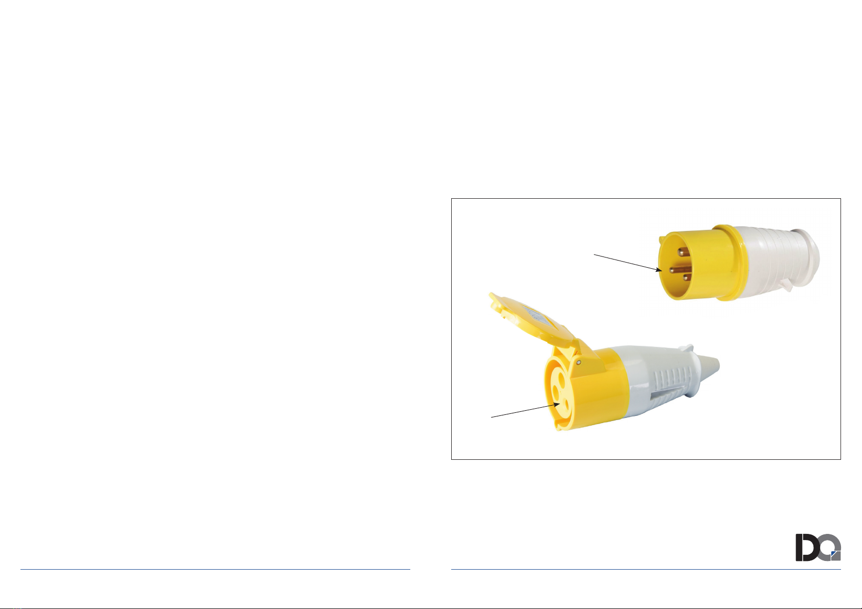
This tool is intended for use on a circuit that has an outlet that looks like those
illustrated below.
Should an alternative connection type need to be used, please consult local advice and
guidance to the country of use, to ensure appropriate and effective electrical compliance is
maintained for maximum safety and protection to the user, and the immediate work area
and its occupants.
Note: In Canada, the use of a temporary adapter is not permitted by the
Canadian Electrical Code.
Grounding Pin
Pin Socket
Diaquip Standard 110V Plug and extension socket with integrated grounding pin

/14 WWW.DIAQUIP.CO.UK WWW.DIAQUIP.CO.UK /15
ELECTRICAL CONNECTION
The network voltage must conform to the voltage indicated on the tool name plate. Under no
circumstances should the tool be used when the power supply cable is damaged. A damaged
cable must be replaced immediately by an authorized Customer Service Center. Do not try to
repair the damaged cable yourself. The use of damaged power cables can lead to an electric
shock.
WARNING: Never operate a damaged machine.
Always tag a damaged machine and take it out
of service until repairs can be made.
WARNING:ThismachinerequiresaPortable
Residual Current Device (PRCD) also known as
a Ground Fault Circuit Interrupter (GFCI). The
110 Volt version of this machine relies on the
110 Volt transformer providing this PRCD.
Always ensure that the transformer being
used is showing no signs of damage to the
casing and that there is a reset button present.
The230Voltversionofthismachineisequipped
with its own in-line PRCD. Always use this device
whenever using the machine to reduce the risk of shock hazards.
Always position the PRCD as close as possible to the power source. Test and reset the
PRCDdevicebeforeeachuse.Pressthe“Test”buttontotest.Pressthe“Reset”button
to energize the circuit to the machine.
WARNING: Always connect the plug into the wall socket with a drip loop. If the cable
leads downward directly into the wall socket, any water on the cable could run into the
socket, causing a hazard.
Note: PRCD (GFCI) appearances
vary according to the requirements of
various regions. Photos for reference
only
INTRODUCTION
This machine is equipped with two handles and a blade guard. The motor has overload and
overheat protection. It has an integrated water feed system as required for diamond cutting. It
must only be used with a diamond blade. It is intended for cutting masonry, stone, concrete,
reinforced concrete and similar materials. All other uses are prohibited.
LIST OF CONTENTS
Concrete Saw
Guide Roller Assembly
M17 Combination Wrench
Splash Guard
Allen Key
ASSEMBLY
Mount the blade. ( See below “Mounting the Blade”)
Mount the Guide Roller Assembly if desired ( See below “Guide Roller Assembly”)
Mount the blade guard brush (See below “Blade Guard Brush” for assembly instructions)
Mount the splash guard (See below “Splash Guard” for assembly instructions)
Cover
Test Button Reset Button On Lamp
LIST OF OPTIONAL CONTENTS
Flush Cut Flange with tools & xings
Dust Ski (Coming 2019)
400mmØ Blade

/16 WWW.DIAQUIP.CO.UK WWW.DIAQUIP.CO.UK /17
DIAMOND BLADES
Allowed Types Of Blades
This machine may use diamond blades only.
NOTE: Abrasive wheels may not be used on this machine.
Only use either segmented or continuous rim diamond blades.
If the diamond blades are segmented, the maximum allowable peripheral gap between
segments is 10mm and must be with a negative rake angle.
Only diamond blades of 405mm (16”) or less may be used.
Blade thickness must be at least 2.0mm and no greater than 6.35mm
Blade Storage And Transport
Do not store or transport the machine with the blade mounted. Remove the blade and store in
such a way that it is protected from being bent or damaged when the machine is not in use-this
will help prevent damage to the blade.
A damaged blade can cause irregular conditions, this can cause imbalance and result in a
hazard. Always inspect new blades for storage or transport damage.
DIAMOND BLADES
About Diamond Blades
Diamond blades consist of a steel core with diamond segments added to its periphery.
Diamond blades are available for different hardnesses of masonry materials, stone, concrete,
reinforced concrete, etc.
Some diamond blades are designed to be used wet only, while others are designed to be
allowed to be used dry. Refer to the blade manufacturer’s instructions.
Generally speaking, even if the blade is specied as a dry type blade, diamond tools always
work better when wet, and dry cutting should be limited to situations in which water cannot or
should not be used. Water will prevent the blade from overheating, greatly reduce the amount of
harmful dust created by cutting, remove the slurry from the cut, and extend the life of the blade.
Diamond is the hardest substance known, but even diamond is unable to withstand extreme
overheating combined with the cutting forces involved. Dry cutting of very hard materials such
as porcelain or reinforced concrete will lead to rapid tool wear and possible failure.
The diamond impregnated segments in a sintered diamond blade operate on a principle of
controlled erosion. The blade does not cut the material, rather it grinds it away. The bond matrix
holding the diamonds is continually worn away by abrasion with the workpiece, exposing the
harder diamonds to stand proud from the bond matrix. A blade with good diamond exposure is
a sharp blade. Blades made for cutting harder materials will have a softer bond, allowing the
diamonds project more aggressively (but will not last as long).
Blades made for cutting softer, abrasive materials will have a harder bond, allowing them to
resist the abrasiveness of the material and to last longer. The other factor is the grit size of the
diamonds themselves: very hard materials tend to require a ner grit size, while coarser grits
will cut faster.
This erosion process causes heat and particles, which require water to cool and rinse free.
Without adequate water, the blade would overheat and be destroyed.
With too much water and not enough feed pressure, there would not be adequate erosion of the
bond matrix (the diamonds not exposed) and the blade becomes dull (diamond segments polish
smooth). This is called glazing and luckily the blade can be de-glazed (sharpened). If the blade
seems to refuse to cut anymore, you know that it is glazed.

/18 WWW.DIAQUIP.CO.UK WWW.DIAQUIP.CO.UK /19
DIAMOND BLADES
About Diamond Blades (continued)
See below: “SHARPENINGAGLAZEDBLADE”
Never use a sharp motion or the blade will be damaged. Conversely, don’t feed too gently
or the diamond segments will become glazed. Keep the blade steadily working, but don’t be
abusive or give the blade shock impacts into the work surface.
Take great care to keep the blade perpendicularly aligned to the kerf. If the blade is crooked,
it will easily bind. When cutting reinforced concrete, if embedded steel such as rebar is
encountered, take special care. When the steel is encountered, the water will generally go
clear and vibration will begin. Reduce the feed pressure by about 1/3 and let the blade go at its
own pace, if there is too much vibration the blade may be destroyed. Once the steel is passed,
continue normally. A properly sharp blade with good diamond exposure should be able to
cut through rebar if handled well.
NOTE: Never use a wet-type diamond blade without water. It will overheat and be
destroyed.
NOTE: When using dry blades, do not allow them to overheat. It is best to cut no longer
than about 60 seconds at a time, with 10 second running in air cool down times in
between.
Always mount the blade with the arrow matching the direction of rotation of the machine (A
direction arrow is marked on the blade guard).
WARNING: Never use blades for cutting a material other than the material they were
intended for.
SHARPENING A GLAZED BLADE
Diamond blades may become glazed (dull) for various reasons, such as cutting reinforced
concrete with an excess of embedded steel, or from cutting with too little downforce which can
lead to the segments becoming polished or “glazed”. Once the diamond segments are glazed,
the blade’s cutting performance will degrade and the segments will overheat. To resharpen the
blade, turn down the water feed and make a few cuts in a very soft, abrasive material such as
brick.
MOUNTING THE BLADE
First make sure that the machine is unplugged.
Then, using the 17mm combination wrench, engage the arbor bolt and turn the arbor while
pressing on the arbor lock (See page 2). When the arbor reaches the right position, the arbor
lock will be allowed to engage. Then the arbor bolt may be loosened and the plain outer ange
may be removed. (It is a standard, right hand thread, so turn anticlockwise to loosen.)
The inner anges are specic to the blade arbor bore diameter. There are three possible blade
arbor bore sizes depending on the market where the machine is sold: 20mm, 22.2mm (7/8”),
and 25.4mm (1”) Check the inner ange to ensure that the size matches the bore of the blade
which you intend to use.
The 7/8” and 1” sizes each have a specic inner ange which must be used. For the 20mm
size, the bore directly engages the arbor and thus uses a plain ange on both the inside and
outside.
Inspect the blade before use. It must not be cracked, warped or damaged in any way that would
cause a hazard in operation. Loose diamond segments can be ejected at high speed, causing
possible injury. Always check that the diamond segments are not under cut. If the diamond
segments are thinner or nearly thinner than the blade core, the kerf will be too tight tting and
could easily lead to kickback.
Ensure that the anges and blade bore are clean and undamaged and that everything ts
properly. The anges may not be used if they are warped, the surface is uneven, burred or if
they are dirty. The arbor bolt and arbor threads must be undamaged. Inspect the blades for
segment damage, arbor hole damage or any other damage which could cause hazardous
operation.
The protruding edge of the inner ange should be facing the blade. Then mount the blade to the
inner ange and add the outer ange. Add the arbor bolt and tighten to 15-25 Nm.
WARNING: Do not attempt to mount a blade which does not match the mounting
hardware. It will lead to eccentric running and vibration which will be uncontrollable.

/20 WWW.DIAQUIP.CO.UK WWW.DIAQUIP.CO.UK /21
ADJUSTING THE BLADE GUARD
The blade rotates clockwise when viewed from the arbor end. Therefore, most of the cutting
debris, sparks and slurry is thrown to the rear. So the blade guard should be adjusted so that
the rear edge is ush with the workpiece.
TO ADJUST
First pull out the locking lever against the spring
tension, then rotate the blade guard to the desired
position. Allow the locking lever to engage the
nearest slot in the guard to lock it into position.
Blade Guard Locking Lever
BLADE GUARD BRUSH
There is a removable brush at the rear of the guard to help contain sparks, dust, debris and
slurry. To install, simply push the brush into the slot in the bottom of the dust port bracket until it
clicks in place. This brush may be pulled straight out to replace when worn.
SPLASH GUARD
The spring-loaded splash guard is useful to help to contain slurry which splashes toward the
back. To install, simply clip into place on the back of the dust port bracket. To remove, tilt
upward to pop free. If the splash guard is not needed, such as when cutting dry, it may be
clipped up out of the way. Simply engage the male clip on the ap with the female clip on the
mount. Unclip to release.
WATER CONNECTION
Water is a basic requirement for diamond sawing with
wet-type diamond blades. The water serves as a coolant to
avoid the working surface of the diamond segments from
overheating. When the diamond bit becomes overheated,
both the bond matrix and even the diamonds break down,
thus destroying the blade. Besides cooling, water also
keeps down dust and ushes away abrasive particles.
WARNING: Always ensure a PRCD (GFCI) is used
when operating with water
WARNING: Never allow water to enter the motor. It could lead to an electric shock.
WARNING: Check all connections of the water feed system to ensure there are no leaks.
Inspect hoses and other critical parts which could deteriorate.
WARNING: The maximum water pressure should not exceed 70 psi (4bar).
Use a water collector with a wet vacuum to collect cooling water if nearby objects could be
damaged by water. The water feed system is built into the machine. To connect with the water
supply, rst pull the quick-release collar to remove the female side of the water coupling. Then
unscrew the nut and engage the coupling to the water hose. Now reconnect the water coupling
to the male water feed valve. Press it until it clicks. The water ow is controlled by the water
feed valve. The water to the blade may be nely adjusted to the required amount and no more.
NOTE:Contaminantsinthewatersupplycaneasilyplugupthenewaternozzlesinthe
bladeguard.Ensurethatthesupplywaterisclean.Ifyoundthatthereisnowaterow
to the blade, then clean out the water feed system on the machine.
GUIDE ROLLER ASSEMBLY
The guide rollers make it easier to keep the blade plane
perpendicular to the workpiece. To install, slacken the buttery
bolt slightly and engage the four claws with the four eyelets
on the bottom of the motor housing, then tighten the buttery
bolt. Note that roller assembly is offset to one side to avoid
contacting the blade, so it may only be installed in one
orientation. If it is not needed, the guide roller assembly may
be removed and set aside.
Buttery Bolt
Open
Closed Water Feed Valve
/22 WWW.DIAQUIP.CO.UK WWW.DIAQUIP.CO.UK /23
OVERLOAD & OVERHEAT PROTECTION
Overload & Load Warning Lamp
When full load is reached, the load warning lamp will ash red.
If full load is exceeded and sustained for too long, the motor
will shut down and the load warning lamp will glow solid red.
In this case, the motor must be rst shut off and then restarted.
When this happens, the motor will very likely be near
overheating, so it is also a good idea to run the motor at no
load for a few minutes to cool it before continuing.
Overheat Thermal Protection
If the temperature of the motor gets too high, the thermal protection will shut the motor down.
The switch must be rst shut off and then restarted. When this happens, do not immediately
start cutting after restarting the motor. Always run the machine at no load for a few minutes to
return to a normal operating temperature
before continuing.
CAUTION: The motor will be damaged if it is repeatedly overloaded or overheated.
Always cool the motor by running at no load for a few minutes whenever it stops from
either overheat or overload.
Load Warning
Lamp
OPERATION
How to hold the machine
Always hold the machine with both hands,
with the right hand on the main handle
and with the left hand on the side handle.
(This applies even if the operator is
left-handed)
Do not stand directly in line with the blade.
Rather, stand in such a way that, if it kicks
back, you will not be in the path of the blade.
Never lean over the blade path. That would put your body in line with the blade if it
kicks back.
Do not cut above shoulder height.
Never cut while standing on a ladder or other unstable platform.
While cutting on a vertical surface like a wall, hold the machine in a “tail down” position in
such a way that the upper quadrant of the blade does not contact the workpiece.
Before cutting
Check the area where the cut is to be
made to ensure that it is clear of objects
which could cause the operator to
stumble.
Before cutting, it is sometimes useful to
mark the line of cut with chalk or the like. For straight cutting, a wood plank is also useful in
guiding the machine to make a straight cut.
Ensure that all bystanders are at a safe distance.
Ensure that the equipment is grounded.
Ensure that all safety equipment is in place.

/24 WWW.DIAQUIP.CO.UK WWW.DIAQUIP.CO.UK /25
OPERATION
Proper Support for the Workpiece
Support the workpiece on in such a way
that the kerf will not pinch down on
the blade.
Secure the workpiece so that it will not
roll, slip away or move due to vibration
while cutting
The cutting sequence is important when
making cutouts. Always make the last cut
in a way that avoids the blade being pinched. Thus, make the bottom horizontal cut rst,
then the sides and nally make the top horizontal cut last.
Make note of the weight of the workpiece and the direction which it will fall when it is cut
through.
Whenever there is a situation where severing the workpiece will cause a hazardous
situation, leave a tab of material intact and nish off the operation with a chisel or the like.
CuttingTechnique
Holding the machine with both hands to resist the start up torque, press the release button
and then squeeze the trigger switch.
Allow the machine to reach full speed before contacting the workpiece.
Adjust the water ow as needed by turning the water feed valve.
Then gently begin the cut with the rear portion of the blade until the kerf is established.
Make the rst cut in the forward direction (so that you can see the line of cut). Then make
following cuts in the backward direction.
Do not try to cut too much depth in one pass. Never exceed about 50mm (2”) per pass. It
is better to cut in multiple passes to minimize the cutting contact area of the blade and
keep the blade spinning fast.
OPERATION
CuttingTechnique(continued)
It’s a good idea to rst cut a shallow guiding groove in the forward direction before
proceeding to make the main cut in the backward direction. If any correction is needed.
Lift the blade and cut slightly ahead and then back into the existing kerf. Take care to avoid
the blade being pinched.
In round workpieces, the best technique is to use a slow, uniform back and forth motion
while cutting with the bottom quadrant of the blade.
Do not allow the machine to bog down. Limit your feed pressure to keep the blade spinning
at high speed.
Never side load the blade in the kerf.
If the workpiece is very heavy and may cause a hazard when it is cut through, do not cut
all the way through the material. Leave some tabs of material intact and then nish the cut
with a chisel or similar tool.
Concrete cutting is very stressful for the motor: After the cut is nished, it is a good practice
to run the machine at no load for a short time to lower the motor temperature before
stopping.
Stopping
Release the trigger to stop the machine. After the trigger is released, the blade will continue
spinning for a time.
WARNING: Do not set the machine down until the blade has stopped turning.
Release Button
Trigger Switch
12
1. Forwards
2. Backwards
/26 WWW.DIAQUIP.CO.UK WWW.DIAQUIP.CO.UK /27
FLUSH CUTTING FLANGE (IF APPLICABLE)
FITTING & OPERATING
CONTENTS WITH THE FLANGE
OPERATION
1. Remove the water hose from the water nozzle
on the outer blade guard and connect it to
the alternate water nozzle on the inner blade
guard.
2. Remove the 6 screws securing the outer
blade guard.
3. Unclip the 3 toggle latches and pop the loose
clasps in the plastic clips to prevent rattling.
4. Lift away the outer blade guard and keep in a safe place.
5. Once the ush cutting operation is completed, immediately replace the outer blade guard
and water hose.
NOTE: There is roughly a 1mm or less effective offset (Depending on the width of the
diamondsegments).Sincethebladeguardhassomedegreeofexibility,pushingdown
slightlybringsitallthewaytofullyush.Inactualcutting,itcomesout100%ush.
There has to be a small degree of offset so the blade won’t make marks in the base
material, in cases where it matters. So to avoid the marks, don’t use any downforce.
Buttoget100%ush,usesomedownforce.
WARNING: Always operate with the outer blade guard in place while performing standard
cutting.Neveroperatethesawwiththeouterbladeguardremovedexceptforush
cutting operations.
WARNING: Check the tightness of the mounting screws and arbor screw periodically.
WARNING:Ifanyunusualvibrationisfeltinoperation,stopimmediatelyandndthe
cause before continuing.
Alternate Water Nozzle
INTRODUCTION
The ush cutting kit enables a ush cut 400mmØ
blade (not included) to be mounted to the machine in
order for ush cuts to be made while the outer blade
guard is temporarily removed. The ush cut blade
may be left in place and the operator may return to
standard cutting simply by replacing the outer blade
guard and securing it with the 3 toggle latches. This
way, it is quick and convenient to switch between
the standard mode and ush cutting mode. If more
appropriate for the operator & circumstances, the
ush cutting blade and ange may be removed
and the machine is then returned to the standard
conguration.
1. Flush Cutting Flange
2. Socket Cap Arbor Bolt & Washer
3. Flat-Head Socket Cap Screws x 6
4. M5 L-Hex Wrench
5. M8 L-Hex Wrench
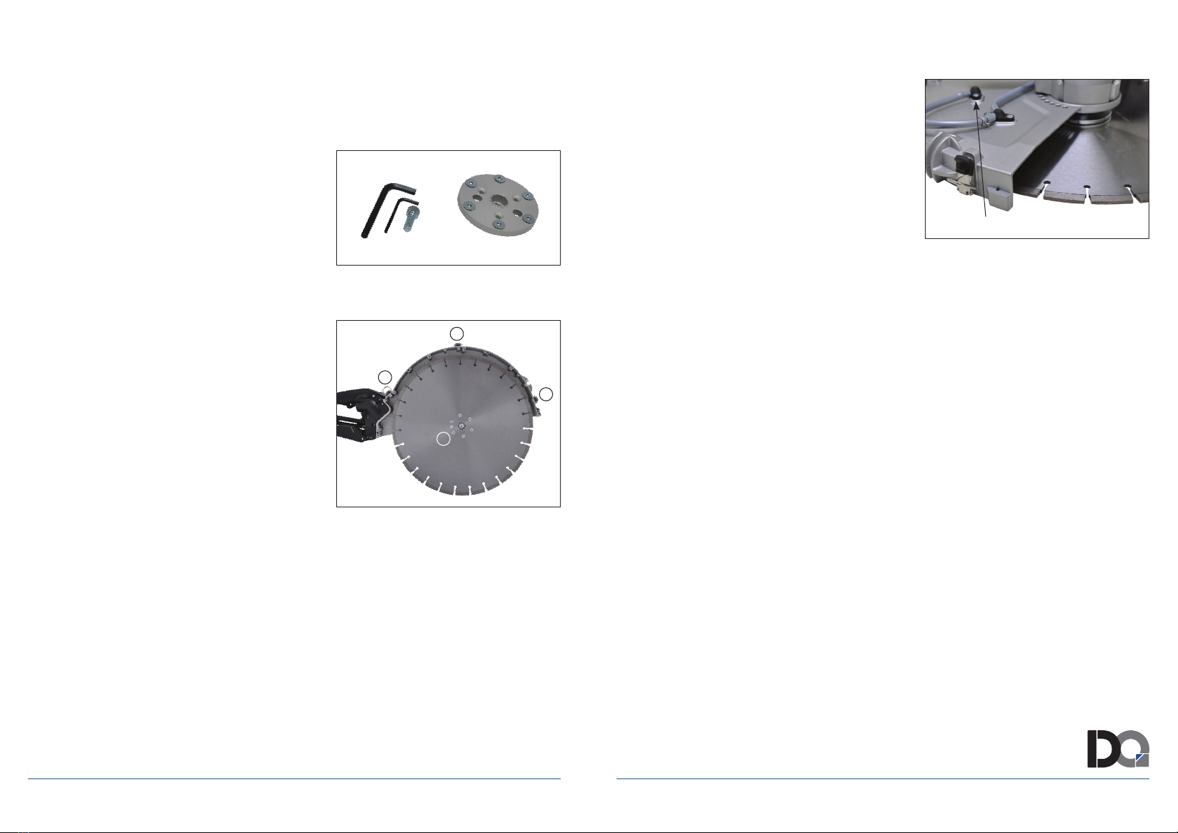
ASSEMBLY
To mount the ush cutting kit, rst remove the standard arbor bolt, anges and blade according
to the instructions below;
1. Mount the ush cutting ange on the spindle and secure with the washer and socket cap
arbor bolt. Engage the arbor lock tighten the arbor bolt securely using the M8 L-hex
wrench.
2. Mount the ush cut blade on the ange, align the holes and thread in the at-head socket
cap screws. Using the M5 L-hex wrench, tighten the screws evenly and diagonally.
1. Toggle Latches
2. Flat-head Socket Cap Screws
1
1
1
2

/28 WWW.DIAQUIP.CO.UK WWW.DIAQUIP.CO.UK /29
MAINTENANCE AND CLEANING
This machine operates in a very harsh environment. The slurry created by wet cutting and the
dust created by dry cutting gets sucked into the motor’s cooling slots and enters the motor. The
slurry of brick and concrete contains salts and other corrosive substances which will severely
shorten the life of the motor or cause electrical shorts if allowed to accumulate.
Therefore, it’s essential for the long life of the tool that it be thoroughly cleaned after each use.
Compressed air should be blown through the machine’s cooling slots at the back of the
machine while the motor is running.
Daily Maintenance
Keep the machine clean
Check to ensure that the power supply cable is in good condition.
Ensure all screws are tight.
Check the condition of all safety equipment such as the blade guard
Check the blade for damage.
MAINTENANCE AND CLEANING
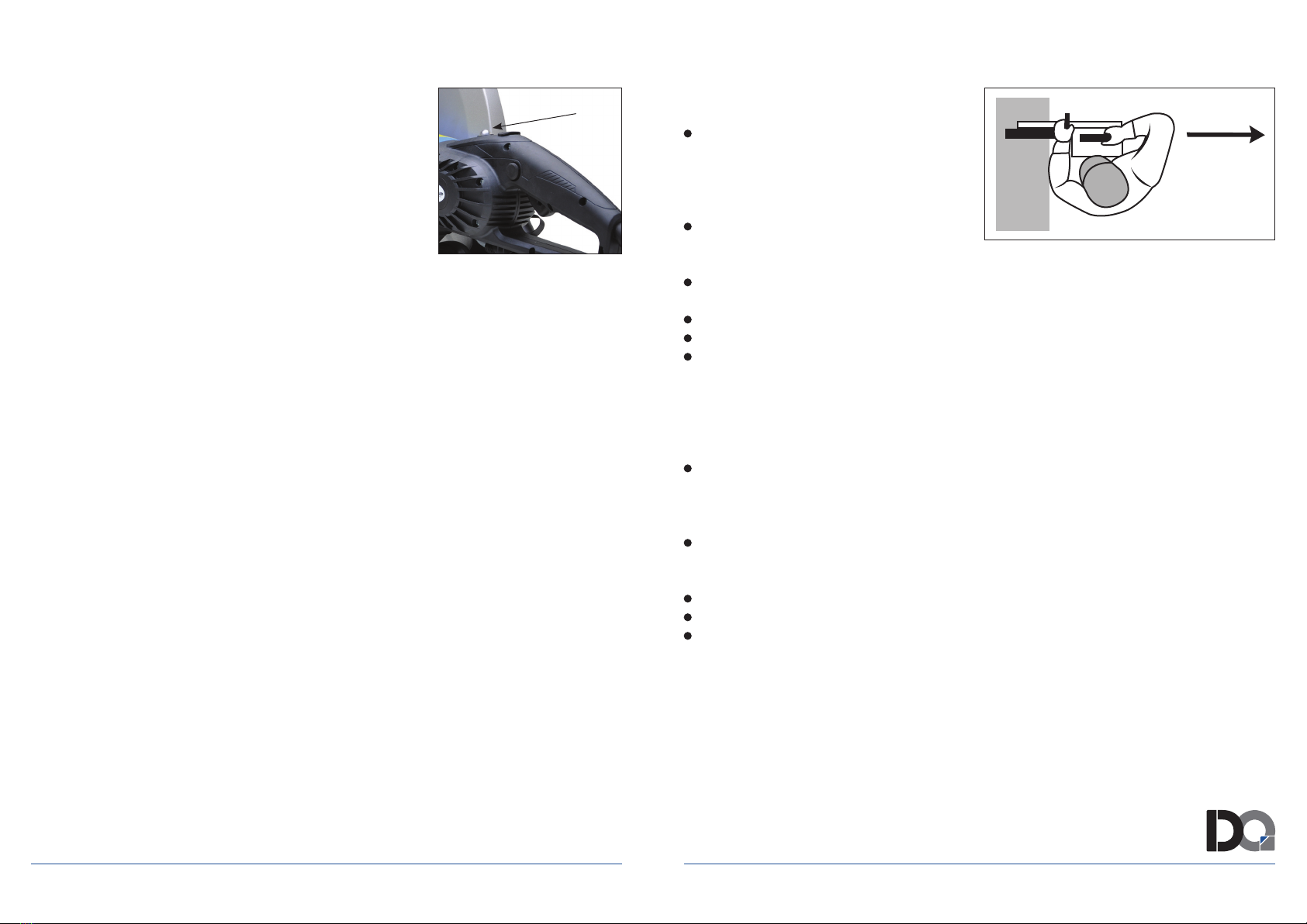
Carbon Brushes
The carbon brushes are a normal wearing part and must be replaced when they reach their
wear limit. This machine is equipped with auto-stop carbon brushes. If the machine comes to
a stop unexpectedly, the brushes should be checked. The auto-stop brush design protects the
motor by stopping the machine before the carbon brushes are completely worn out.
Caution: Always replace the brushes as a pair.
To replace:
1. Remove the screw and remove the brush cover.
2. Using pliers rotate the brush spring out of the way
and slide the old carbon brush out of the brush holder.
3. Unscrew the screw to remove the brush lead.
The old carbon brush may now be lifted away.
4. Install a new brush. Installation is the reverse of
removal.
5. Replace the brush cover.
If the replacement of the power supply cord is necessary, this has to be done by the
manufacturer or their agent in order to avoid a safety hazard.
WARNING: All repairs must be entrusted to an authorized service center. Incorrectly
performedrepairscouldleadtoinjuryordeath.
Do not throw electric power tools into the household waste!
In accordance with the European Directive 2002/96/EG on Waste Electrical and Electronic
Equipment and transposition into national law, used electric power tools must be
collected separately and recycled in an environmentally friendly manner.
Brush Cover

/30 WWW.DIAQUIP.CO.UK WWW.DIAQUIP.CO.UK /31
WIRING
CARBON
BRUSH
CARBON
BRUSH
MOTOR
AC SWITCH
1
2
1
2
ELECTRONICS
UNIT
Te mperature Sensor
Diaquip hereby declare that the said products conform with the requirements
demanded to be met for CE and EMC Certication and regulations.
ATTESTATION OF CONFORMITY | EXTRACT
Product: QHS-400 Concrete Saw (Cut-off Machine)
Trade Name: DQ Machinery
Type/Model: QHS-400 in 110 & 230V
Requirements: EN ISO 12100:2010 – Safety of machinery. General
principles for design. Risk Assessment & Risk Reduction.
EN 60745-1:2009 +A11:2010
EN 60745-2-22:2011+A11:2013
This attestation is granted on account of an examination by a certied regulatory body,
the results of which are laid down in a condential le.
This attestation implies that the examined types are in accordance with the standards
designated under the Machinery Directive 2006/42/EC.
09 March 2018

APPROVED SERVICE CENTRE;
WWW.DIAQUIP.CO.UK
0161 406 0609
SALES@DIAQUIP.CO.UK
DIAQUIP HEAD OFFICE | MANCHESTER, UK
Table of contents
Other DIAQUIP Saw manuals


