Dictator SQUARE 940-2 User manual

Technical Manual
SQUARE 940-2
© DICTATOR Technik GmbH • Gutenbergstr. 9 • 86356 Neusäß • Germany
Tel. +49(0)821-24673-0 • Fax +49(0)821-24673-90 • E-mail info@dictator.de • 20200619 Page 04.046.1
Technical Manual
SQUARE 940-2
You can find the current version of our manual on our website under «Downloads»:
https://en.dictator.de/products/door-drives-gate-drives/control-systems/

Technical Manual
SQUARE 940-2
© DICTATOR Technik GmbH • Gutenbergstr. 9 • 86356 Neusäß • Germany
Tel. +49(0)821-24673-0 • Fax +49(0)821-24673-90 • E-mail info@dictator.de • 20200619
Page 04.046.2
General product description ......................................... 04.046.04
I. Basic safety instructions, terms and definitions.............. 04.046.08
I/1 General information .......................................... 04.046.08
I/2 Safety instructions ............................................. 04.046.08
I/3 Overview control system .................................... 04.046.11
II. Mechanical mounting............................................... 04.046.13
III. Controller functions ................................................. 04.046.14
IV. Electrical connection .............................................. 04.046.16
IV/1 Fuse protection/main switch....................................... 04.046.16
IV/2 Connection of external devices................................... 04.046.16
IV/3 Cables .................................................................... 04.046.16
IV/4 Carrying out the teach-in run...................................... 04.046.16
IV/5 Termination of wiring................................................. 04.046.16
IV/6 Mains connection ..................................................... 04.046.17
IV/7 Motor connection...................................................... 04.046.18
IV/8 Connection motor brake ............................................ 04.046.19
IV/9 Connection temperature sensor................................... 04.046.20
IV/10 Rotary encoder....................................................... 04.046.20
IV/11 Reference limit........................................................ 04.046.20
IV/12 Limit switch ............................................................ 04.046.21
IV/13 Safety edge ........................................................... 04.046.22
IV/14 Light barriers/Light curtain ....................................... 04.046.22
IV/15 Control signals ....................................................... 04.046.25
IV/16 Membrane keys...................................................... 04.046.25
V. Menu system and description ................................... 04.046.26
V/1 Navigation ............................................................... 04.046.26
V/2 Menu structure .......................................................... 04.046.27
V/3 Main menu ............................................................... 04.046.28
V/4 Submenu .................................................................. 04.046.28
V/5 Display indication...................................................... 04.046.29
V/6 Express menu............................................................ 04.046.30
V/7 Main menu ............................................................... 04.046.31
V/8 System Status ............................................................ 04.046.31
V/9 Door type ................................................................. 04.046.33
V/10 Door positions......................................................... 04.046.33
V/11 Limit Setup .............................................................. 04.046.34
V/11 Limit Setup - Operation mode ............................... 04.046.35
V/12 System Setup........................................................... 04.046.36
V/12 System Setup - Timer............................................ 04.046.36
V/12 System Setup - Outputs ........................................ 04.046.37
V/12 System Setup - Inputs................................................ 04.046.39
V/12 System Setup - Displacement sensor....................... 04.046.41
V/12 System Setup - References .................................... 04.046.42
V/12 System Setup - Safety devices ............................... 04.046.43
V/12 System Setup - Motor adjustment........................... 04.046.44
V/12 System Setup - Frequencies................................... 04.046.47

Technical Manual
SQUARE 940-2
© DICTATOR Technik GmbH • Gutenbergstr. 9 • 86356 Neusäß • Germany
Tel. +49(0)821-24673-0 • Fax +49(0)821-24673-90 • E-mail info@dictator.de • 20200619 Page 04.046.3
V/12 System Setup - Ramps.......................................... 04.046.47
V/12 System Setup - Specials........................................ 04.046.48
V/12 System Setup - System.......................................... 04.046.49
V/13 Wireless Setup ........................................................ 04.046.49
VI. Setup.................................................................... 04.046.51
VI/1 Placing into operation with encoder - General information ..............
.................................................................................. 04.046.51
VI/2 Placing into operation with encoder - Preparation .......... 04.046.51
VI/3 Placing into operation with encoder - Quick Setup ......... 04.046.52
VI/4 Placing into operation with limit switches - General information. ......
......................................................................... ........ 04.046.54
VI/5 Placing into operation with limit switches - Preparation.....04.046.54
VI/6 Placing into operation with limit switches - Quick Setup .. 04.046.55
VII. Troubleshooting..................................................... 04.046.57
VII/1 Error codes ............................................................. 04.046.57
VII/2 Repair and maintenance ........................................... 04.046.60
VII/3 Change log............................................................. 04.046.60
VIII. Appendix ............................................................ 04.046.61
VIII/1 Technical Specifications................................... 04.046.61
VIII/2 Declaration of Incorporation ............................ 04.046.63

Technical Manual
SQUARE 940-2
© DICTATOR Technik GmbH • Gutenbergstr. 9 • 86356 Neusäß • Germany
Tel. +49(0)821-24673-0 • Fax +49(0)821-24673-90 • E-mail info@dictator.de • 20200619
Page 04.046.4
Summary
SQUARE 940-2 Control System
with Frequency Converter According to EN 12453
The SQUARE 940-2 control system has
been developed for the DICTAMAT AC-21
door operators (sliding door operator DIC-
TAMAT 900-21 and hinged door operator
DICTAMAT 310-21). It meets the de-
mands of the EN 12453 concerning
the safety of powered doors.
Its main advantages are:
- Autocontrol, i.e. it shuts itself down
automatically upon detecting an error
that might lead to a dangerous situation.
- Direct connection of safety equipment
according to the EN 13849-1 wit-
hout additional evaluation device.
- Different "Stops" of the door
adjustable. This protects door and
door operator during normal operation
from unnecessary wear and tear due to
an abrupt Stop. In case of danger the
maximum stopping distance according
to the EN 12453 is observed.
- Connection possibility for a mechanical
braking device.
- The SQUARE 940-2 allows for a position
control by an encoder and thus a very
exact positioning.
- Graphic display on the casing lid with
status and error indication.
- The membrane keys on the lid of the
casing serve for operating the door.
Motors to be connected three phase 230/400 VAC, max. 0.75 kW
Main features
position control: encoder or separate limit switches
integrated frequency converter
password protected acces to adjustment facility
deadman, impulse or automatic operation
emergency service in case of faulty safety equipment
5 adjustable relay contacts
Meets the safety demands of EN 12453.
Technical Manual
SQUARE 940-2
© DICTATOR Technik GmbH • Gutenbergstr. 9 • 86356 Neusäß • Germany
Tel. +49(0)821-24673-0 • Fax +49(0)821-24673-90 • E-mail info@dictator.de • 20200619 Page 04.046.5
335
118335
STOP
SQUARE
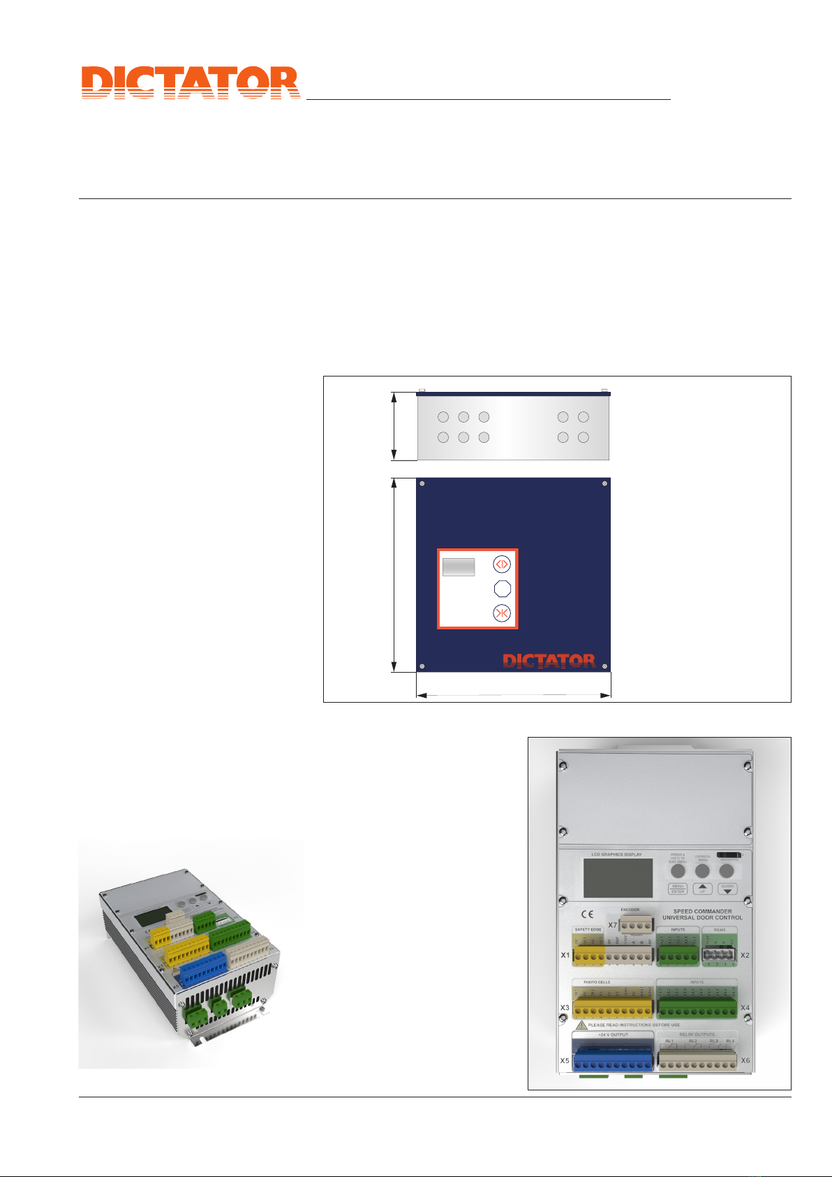
Dimensions / Installation
The casing of the SQUARE control systems has been designed with as small as possible
outer dimensions, in order to fit also into limited space. The interior of the casing,
however, offers sufficient space to house - if necessary - additional devices or batteries.
The carrier board is provided with threaded holes for standard top hat rails. This saves
the expenses for additional casings, their installation and connection.
The installation of the control system
is very easy, as the electronics
are fixed on a board that can
be removed completely from the
casing. The lid of the casing can
also be taken off, as the flat cable
connection to the display in the lid
just has to be unplugged. The now
very light casing can be fixed to the
wall, without the danger of dama-
ging the electronics by chance with
e.g. a screw driver.
The control system should be placed
not farther than 30 m from the door
operator.
Door operator, operating elements
and safety equipments are connec-
ted to the removable binders.
The blocks of binders are coded and
therefore cannot be plugged into a
wrong position.
Dimensions of the Casing
Installation / Electrical
Connection of Door
Operators
Dimensions in mm
Marked holes for
10 screw cable inlets M20

Technical Manual
SQUARE 940-2
© DICTATOR Technik GmbH • Gutenbergstr. 9 • 86356 Neusäß • Germany
Tel. +49(0)821-24673-0 • Fax +49(0)821-24673-90 • E-mail info@dictator.de • 20200619
Page 04.046.6
Functions, Programming and Adjusting
Programming and
Adjusting
The SQUARE 940-2 control system permits to adjust the DICTATOR DICTAMAT door
operator exactly to each door. This is a vital condition for the safety at powered doors.
The increased demands concerning the safety of the "machine door" due to the EN12453
standard require a control and putting into operation by a trained and authorised techni-
cian. Therefore all safety relevant parameters are only accessible through a password. The
below mentioned functions and parameters only give a general idea as the SQUARE940-2
offers a much larger range of adjustments/functions.
All adjustments are done with the three adjustment keys on the control module.
•Dead Man or Impulse Function
for the keys
OPEN
and
CLOSE
(can be choosen separately
for both directions, e.g. impulse OPEN, dead man CLOSE)
•Automatic Closing: As soon as the position OPEN has been reached the door closes
automatically after a preset time (adjustable between 1 - 999 seconds)
•Alternating Impulse OPEN/CLOSE
, also in combination with automatic closing
•Partial Opening: The door opens only partially after pressing a separate push button
(additional Open position for persons) (separately adjustable hold-open-time for this
position)
•STOP (Normal Stop when opening, Fast Stop when closing).
•EMERGENCY STOP: This works the same way as the safety equipment on the closing
edge. Stopping distance according to EN 12453.
•Safety Equipment (SHE): Different safety equipment can be connected to meet the
EN12453. The function of the safety equipment is cancelled in the final positions.
After the safety equipment has been activated a new operating command is necessary
to get the door moving again.
Securing the closing edge (direction CLOSE): When this SHE is activated, the door
stops within the required distance and then reverses until it is again completely open.
This SHE is in function only during closing.
Securing the opening edge (separate connection): When activated, the door reverses
until it is again completely closed. SHE in function only during opening.
Additional safety type D, e.g. by a light barrier in closing direction (see table on page
04.007.00): Door stops with a Fast Stop (see below).
If the safety equipment should fail, an emergency service for the door can be adjusted
(dead man operation). The door moves at creep speed only. As long as the emergency
service has not been adjusted, the door can no longer be operated by motor.
In order to achieve an optimum adjustment of the door drive to the door different
motor parameters can be adjusted. Amongst them are e.g.:
- Motor Rating (adaption to the connected motor)
- OPENING Speed / CLOSING Speed (separately adjustable)
- Creep Speed before reaching the positions OPEN and CLOSED (speed is reduced
before reaching the final position, so that no separate final dampers are required,
separately adjustable)
- Acceleration and Deceleration Ramps: Depending on the door weight and its easy
movement
- Fast Stop: Adjustment of the Stop in closing and opening direction (separately adjustable)
- EMERGENCY STOP: Adjustment of the STOP characteristics upon activation of the safety
equipment or by the Emergency Stop push button
Motor Parameters
Operating Options /
Safety Features

Technical Manual
SQUARE 940-2
© DICTATOR Technik GmbH • Gutenbergstr. 9 • 86356 Neusäß • Germany
Tel. +49(0)821-24673-0 • Fax +49(0)821-24673-90 • E-mail info@dictator.de • 20200619 Page 04.046.7
SQUARE 940-2 control system for the AC-21 door operators part no. 706094-2
Functions (cont.), Technical Data, Order Information
The SQUARE 940-2 control system permits a great deal of different operating functions.
When choosing the operating mode the required safety equipment has to be provided.
See also the summary on the requirements of the EN 12453 on page 04.007.00. A
change to a "more dangerous" operating mode (e.g. from dead man to impulse opera-
tion) is only permitted when providing the required safety equipment.
The control system offers a high operating standard due to additional adjustment and
connection possibilities.
Order Information
Application Range
SQUARE 940-2
Technical Data
Components Included Control system in casing IP 54 with membrane keys and display on the casing
Diagnostics
Position Control The SQUARE 940-2 control system is designed for a position control via encoder, integrated
in the door operator. This permits a very precise positioning of the door (depending on
the travel and the power transmission: max. 2 mm). However it is also possible to use
separate limit switches (4 pcs. required).
The SQUARE 940-2 disposes of 5 relay contacts for controling signalling and warning
devices. There exists a large variety of adjusting possibilities. This permits e.g. the con-
nection of signals, warning sirens, the connection to a building surveying central, a floor
conveyor system etc.
The display on the lid of the casing indicates error codes or different diagnostic codes for
the input and output terminals. This helps also to locate a problem, even by telephone.
The SQUARE 940-2 control system with integrated frequency converter is designed for
door drives for sliding doors (beginning on page 04.027.00) and for hinged
doors (beginning on page 04.041.00) with a three phase current motor. It can
control motors up to 0.75 kW.
Relay Contacts
Voltage 230 VAC, 50 - 60 Hz
Power consumption 8 A
Output voltage (secondary) 24 VDC
Power supply (secondary) max. 500 mA
Output voltage motor 230/400 VAC (three phase)
Motor rating max. 0.75 kW
Dimensions H x W x D = 335 x 335 x 118 mm
IP rating IP 54
Recommended fuse protection 16 A
Operating temperature -10 °C to +40 °C
AC-21 series DICTAMAT 900-21
DICTAMAT 310-21

Technical Manual
SQUARE 940-2
© DICTATOR Technik GmbH • Gutenbergstr. 9 • 86356 Neusäß • Germany
Tel. +49(0)821-24673-0 • Fax +49(0)821-24673-90 • E-mail info@dictator.de • 20200619
Page 04.046.8
I. Basic Safety Instructions, Terms and Definitions
The installation and commissioning of the SQUARE 940-2 control sy-
stem may only be carried out by trained, expert personnel. All relevant
standards and other valid regulations must be strictly observed. During
commissioning, some safety devices are inactive, so that an additionally
increased hazard potential must be taken into account.
Access to the menu by means of a system-specific password is required
for carrying out commissioning work.
The scope of delivery of each controller supplied includes a separate
supplementary sheet on which the respective password is listed.
The installing specialist company is obliged to ensure that neither the
respective password nor the description falls into unauthorised hands
(e.g. operator), since safety-relevant settings can be changed in the menu.
Improper changes can result in considerable danger to persons and
material.
The SQUARE 940-2 control system was developed exclusively for door ope-
rators that meet the requirements of EN 12453. It is only intended for use
in dry rooms and must be installed inside or on the inside of buildings. The
manufacturer or distributor accepts no liability for applications outside the
defined application purposes or application limits. Proper use also includes
compliance with the operating conditions specified by the manufacturer.
Unauthorized modifications to the SQUARE 940-2 controller exclude
any liability on the part of the manufacturer for any resulting damage.
This door control may only be installed by qualified personnel with
experience with automatic door controls and knowledge of the relevant
EC regulations.
Please read the safety instructions carefully before installation.
• The installer is responsible for the CE marking of the door. The in-
staller must explain the operation of the door to the end customer.
• The SQUARE 940-2 complies with the requirements of EN 13241-1.
I/1 General Information
I/2 Safety Instructions

Technical Manual
SQUARE 940-2
© DICTATOR Technik GmbH • Gutenbergstr. 9 • 86356 Neusäß • Germany
Tel. +49(0)821-24673-0 • Fax +49(0)821-24673-90 • E-mail info@dictator.de • 20200619 Page 04.046.9
I. Basic Safety Instructions and Terms
- cont.
• All components used must be CE approved to provide full CE marking
of the installed equipment.
• The safety edges must comply with EN 12978 and must only be
connected to the terminals provided. These inputs are safety class II
and are monitored internally for correct functioning before each step.
• The control system must be set up in accordance with EN 12453.
The control parameters must be disabled before being handed over
to the customer.
• The cable between motor and control system must be screened and
connected as described in this manual.
• Do not install the controller in direct sunlight as this may cause the
controller to overheat.
• The control unit must not be modified.
• The mains voltage must be switched off before work can be carried
out on the door.
• The connection terminals can carry high voltages up to 5 minutes
after switching off.
• The control panel does not work if the internal 24V-power supply is
short-circuited. The display shows an error message and an alarm
signal sounds.
• The door control must be kept in a good condition to ensure safety
and health.
• The door control may only be used to open and close industrial doors.
• Before use, the door control parameters must be configured in ac-
cordance with EN 12453.
• The door control may only be operated if all safety elements are
functional.
• The door control must not be used if cables connected to the device
are damaged.
Control System

Technical Manual
SQUARE 940-2
© DICTATOR Technik GmbH • Gutenbergstr. 9 • 86356 Neusäß • Germany
Tel. +49(0)821-24673-0 • Fax +49(0)821-24673-90 • E-mail info@dictator.de • 20200619
Page 04.046.10
I. Basic Safety Instructions and Terms
- cont.
Installation • The main switch must be switched off during installation.
• The mains connection may only be carried out by an authorised
electrician.
• During configuration, all personnel must be outside the direction
of travel.
• The door controller must not be mounted on moving or vibrating
parts.
• The door controller must not be installed in a place where it blocks
escape routes.
Cleaning and Maintenance • Before maintenance, cleaning and repair of the installation, the
power supply must be interrupted for at least 5 minutes.
• Do not expose the door control unit to steam or moisture during
cleaning. If necessary, use a cloth moistened with soapy water or
cleaning alcohol.
• Repairs should only be carried out by qualified and trained techni-
cians who have a sound knowledge of the system.
• A complete maintenance/safety check must be carried out at inter-
vals of 12 months by an authorised specialist.
• Only use original spare parts for repairs.
• During the repair, the main switch must be switched off and securely
locked in this position, i.e. the key must be removed.
Inspection and
Repair
Environment and Storage • The door controller must not be installed in a housing that complies
with protection class IP 65 or higher.
• The door controller must not be installed outdoors.
• The door controller must not be installed in hazardous areas.
• Installation and operation may only be carried out in rooms with
less than 90 % humidity.
• The device must be stored under the same conditions as during
operation.

Technical Manual
SQUARE 940-2
© DICTATOR Technik GmbH • Gutenbergstr. 9 • 86356 Neusäß • Germany
Tel. +49(0)821-24673-0 • Fax +49(0)821-24673-90 • E-mail info@dictator.de • 20200619 Page 04.046.11
I/3 Overview Control
System
I. Basic Safety Instructions and Terms
- cont.
Factory setting
User parameters (profile «Std. 50 Hz»)
Revolutions: 1330 r/min.
V/F open: 100 Hz
V/F close: 100 Hz
Boost open: 15 %
Boost close: 15 %
High boost: 0
Switch Frequency open: 8.0 kHz
Switch Frequency close: 8.0 kHz
Position Tol: 2 Pos.
Relay Tol: 10 Pos.
DC Brake Cur: 0 %
DC Brake Time: 0.1 sec, program with 1.0 sec!
Motor Heat: 0 %
Force close: 0.0 sec
Force open: 0.0 sec.
Door speed open: 35 Hz
Door speed close: 25 Hz
Door speed pre open: 15 Hz
Door speed pre close: 15 Hz
Minimum: 10 Hz
Run Timer: 40 sec
Position Sensor: Type 2ph Sensor
Pulse count: 16
Position per meter: 2000
Scale: 0
Referenz: mec. Close
Ramp Acc open: 20 Hz/s
Ramp Acc close: 20 Hz/s
Dec open: 20 Hz/s
Dec close: 20 Hz/s
Dec Stop open: 30 Hz/s
Dec Stop close: 30 Hz/s
Dec emergency: 150 Hz/s
Input configuration beginning with SN 51XXX:
NO Fully open (Input X2/1)
NO Close (Input X2/2)
NO Stop (Input X2/3)
NO Open fully aut (Input X4/1) -> Timer 0.0 sec
NC Stop (Input X4/2)
NO Close (Input X4/3)
NO Open Part 1 aut (Input X4/4)
NO Open/Stop/Close (Input X4/5)
NC Emergency Stop (Input X4/6)
All unused NC inputs must be bridged to X5!
Output functions beginning with SN 51XXX:
Power Relay: Door moving
Relay 4: Door closed
Relay 3: Door opened
Relay 2: Door idle
Relay 1: Door moving
Technical Manual
SQUARE 940-2
© DICTATOR Technik GmbH • Gutenbergstr. 9 • 86356 Neusäß • Germany
Tel. +49(0)821-24673-0 • Fax +49(0)821-24673-90 • E-mail info@dictator.de • 20200619
Page 04.046.12
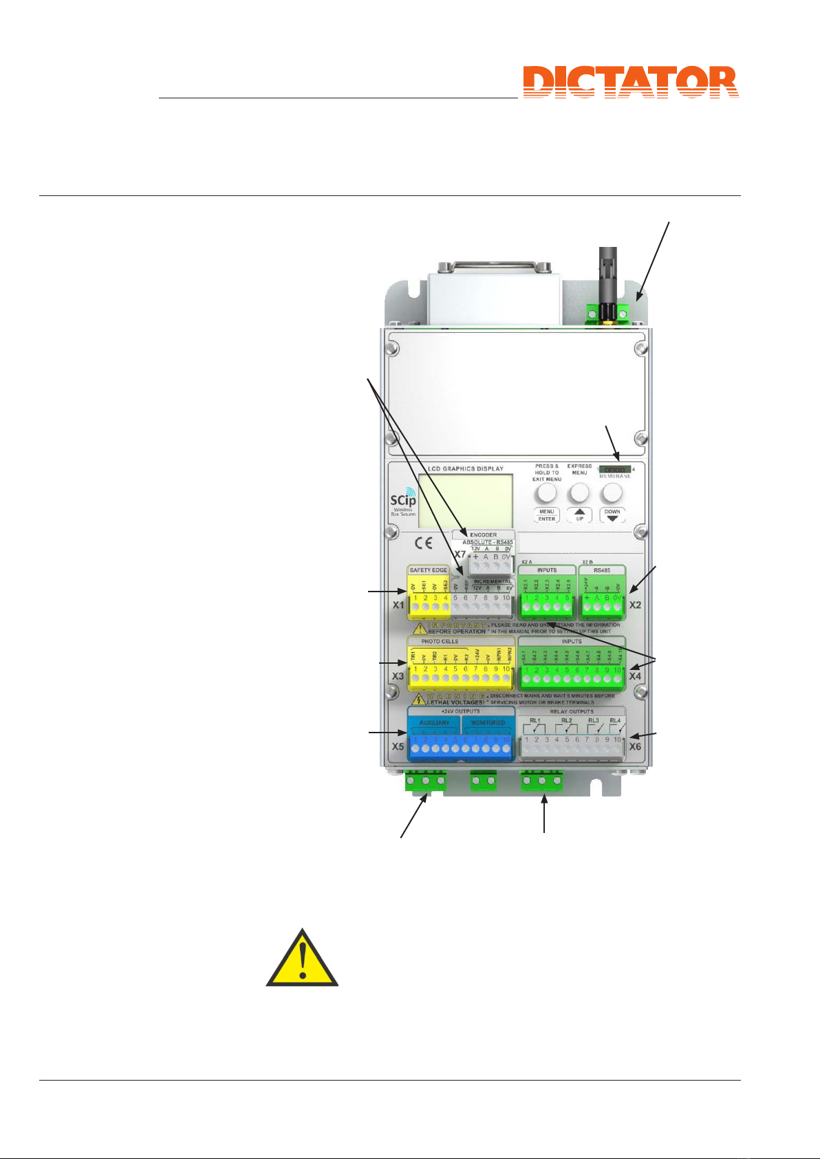
Mains connection
Membrane
keys connection
Rotary encoder
connections
Safety edge
connection
Integrated
photocell
amplifiers
+24 VDC
output
Motor connection Programmable
power relays
Remote
communi-
cation (SCip
protocol)
Programm-
able inputs
Programm-
able relays
It is recommended to use a main switch or CEE plug within
reach of the controller. Connectors and cables must be able
to meet the performance requirements of the control model.
I/3 Overview Control
System - cont.
I. Basic Safety Instructions and Terms
- cont.
Technical Manual
SQUARE 940-2
© DICTATOR Technik GmbH • Gutenbergstr. 9 • 86356 Neusäß • Germany
Tel. +49(0)821-24673-0 • Fax +49(0)821-24673-90 • E-mail info@dictator.de • 20200619 Page 04.046.13
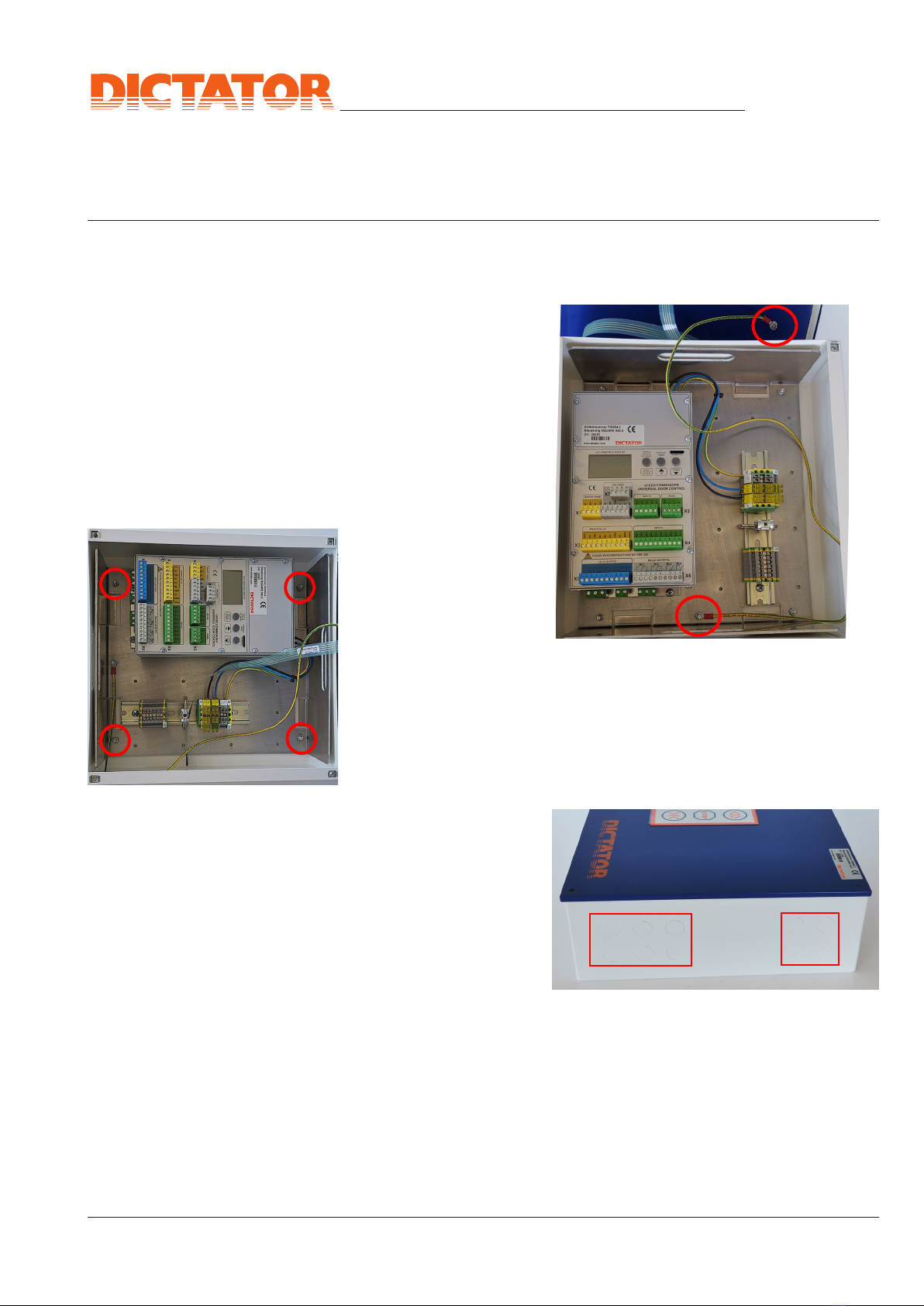
1) Loosen the 4 cover screws and carefully lift the housing cover. Dis-
connect the protective conductor connection on the carrier. Never pull
the cable itself!
The flat cable to the
display is sufficient to
place the cover direct-
ly next to the controller
housing and therefore
does not usually have
to be disconnected.
2) Loosen the four
nuts with which the
carrier is fastened in
the housing with a
socket wrench SW 8
and then lift it comple-
tely out of the housing.
3) Fix the now empty
housing to the wall (4
holes in the bottom of
the housing).
If necessary, use additional sealing washers.
4) Make the required openings for screw connections or strangulation
nipples by breaking out the pre-stamps in the side surface of the housing
with a light blow. A total of 10 M20 screw connections are available.
5) Now insert the carrier
back into the housing
and fasten it with the two
nuts to the bottom of the
housing. Reconnect the
protective conductor of
the carrier!
6) There are threaded
holes on the right side of
the carrier for mounting
top-hat rails. This makes it easy to install additional components such as
relays etc. in the control housing and connect them directly. However, ple-
ase pay attention to possible heat generation and the EMC compatibility.
II. Mechanical Mounting
II/1 Mounting of the
SQUARE 940-2

Technical Manual
SQUARE 940-2
© DICTATOR Technik GmbH • Gutenbergstr. 9 • 86356 Neusäß • Germany
Tel. +49(0)821-24673-0 • Fax +49(0)821-24673-90 • E-mail info@dictator.de • 20200619
Page 04.046.14
III. Controller Functions
The most important functions that can be executed with the SQUARE 940-
2 are described below. Basically, the door can be operated in automatic
mode (a short press on the respective operating element triggers the
operation command) or deadman mode (door moves only as long as
the respective button is pressed). In addition, it is also possible to mix
both operation modes (automatic/deadman) (e.g. automatic OPEN/
deadman CLOSE). If changes occur to certain functions in deadman
mode, these are expressly mentioned.
OPEN: Door moves to the stored OPEN position or until the OPEN limit
switch is reached and automatically stops there.
Person OPEN: Door moves to the end position stored for person ope-
ning and stops there automatically.
CLOSE: Door moves to the stored CLOSED position or until the CLOSED
limit switch is reached and automatically stops there.
Automatic closing: Different times can be stored for the positions
OPEN and PERSON OPEN. The programmed time starts to run as soon
as the door has reached the respective position. When the time has
elapsed, the door closes automatically.
Stop: The stop command can be programmed to stop at different speeds
in the OPEN and CLOSE directions. With a stop command, the door
stops with a corresponding stopping distance.
Emergency-STOP: When the EMERGENCY STOP button is pressed,
the door stops immediately (set max. permissible slowing-down path in
accordance with EN 12453).
Flip Flop: Alternating impulse OPEN/CLOSED. Door can only be closed
when completely open (see reversal of movement).
Safety device(s) (SHE): Stopping distance see EMERGENCY STOP.
The SHE can be parameterised for the closing direction, the opening
direction and the opening and closing directions. The activation of the
SHE can be hidden shortly before reaching the end position.
If the safety device is defective, the control unit displays an error code.
Emergency operation of the door can be achieved by setting the emer-
gency operation in the control unit.
III/1 Controller Functions

Technical Manual
SQUARE 940-2
© DICTATOR Technik GmbH • Gutenbergstr. 9 • 86356 Neusäß • Germany
Tel. +49(0)821-24673-0 • Fax +49(0)821-24673-90 • E-mail info@dictator.de • 20200619 Page 04.046.15
III/1 Controller Functions -
cont.
Motion reversal: As an additional safety function, the direction of a
door movement in progress can only be changed in the OPEN direc-
tion (closing command can be overwritten with opening command). An
opening command CANNOT be overwritten with a closing command.
Reference run: After each power failure, the controller first requests
a reference run. In this case it searches for the reference point (normally
the mechanical stop in position OPEN or CLOSED). The door must be
moved to the reference point by continuously pressing the respective
direction key (stop CLOSED = CLOSE key, stop OPEN = OPEN key) at
the jog frequency speed. Normal door operation is then possible again.
If limit switches are used instead of an encoder, a reference run after
power failure is only required if the door is between the end positions
OPEN and CLOSED. In limit switch operation, the pre-close limit switch is
automatically defined as the reference point. This is always approached
by constantly pressing the CLOSE key (even if the Pre close limit switch
has already been actuated and overrun).
III. Controller Functions
- cont.

Technical Manual
SQUARE 940-2
© DICTATOR Technik GmbH • Gutenbergstr. 9 • 86356 Neusäß • Germany
Tel. +49(0)821-24673-0 • Fax +49(0)821-24673-90 • E-mail info@dictator.de • 20200619
Page 04.046.16
IV. Electrical Connection
The control unit must be fused with 16 A on the mains side. In addition,
a switch or a socket for a pluggable connection cable should be installed
in the immediate vicinity of the control unit, since some error messages
require the control unit to be completely switched off and on again.
Connect all supply lines of your external devices (door
operator, operating buttons, SHE safety devices, limit
switches... if necessary) to the pluggable terminal blocks.
Maximum cable length 30 m.
Please make sure that you use a separate screened cable for the cable
to the motor and to the encoder in the motor.
When inserting all screened connecting cables into the control housing,
use a metal EMC cable gland.
- Motor connection: 4 x 1.5 mm2incl. protective conductor (screened).
Connect the screen both to the motor and to the controller.
Connect the motor in delta connection.
- Motor temperature sensor connection: 2 x 0.5 mm2
- Encoder connection: 4 x 0.25 mm2(screened). Only connect the screen
in the control system.
- Connection of operating elements in controller: 0.5 mm2
A lockable main switch must be connected upstream to the control unit,
which switches off the mains voltage to the control unit at all poles. In
addition, a fuse must be provided on site in the supply circuit to protect
the supply line and terminals.
After connecting the external devices, the teach-in run is carried out while
the housing cover is still open.
After completion of the teach-in run, the protective conductor connection
to the housing cover must be re-established.
Before closing the cover, check again whether all protective
conductor connections have been made reliably!
Now screw on the housing cover again. Make sure that the screws are
tightened only slightly in order not to damage the seal.
The assembly of the device is now completed.
IV/2 Connection of External
Devices
IV/3 Cables
IV/4 Carrying Out of the
Teach-In Run
IV/1 Fuse Protection/
Main Switch
IV/5 Termination of Wiring
Technical Manual
SQUARE 940-2
© DICTATOR Technik GmbH • Gutenbergstr. 9 • 86356 Neusäß • Germany
Tel. +49(0)821-24673-0 • Fax +49(0)821-24673-90 • E-mail info@dictator.de • 20200619 Page 04.046.17
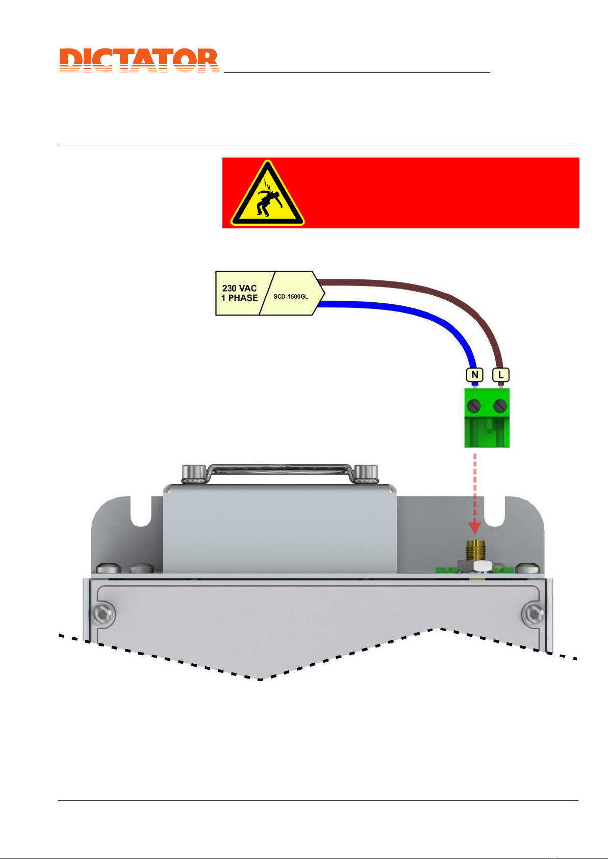
IV. Electrical Connection - cont.
WARNING! ELECTRIC HAZARD!
The mains supply has to be disconnected before
the start of electrical work.
IV/6 Mains Connection

Technical Manual
SQUARE 940-2
© DICTATOR Technik GmbH • Gutenbergstr. 9 • 86356 Neusäß • Germany
Tel. +49(0)821-24673-0 • Fax +49(0)821-24673-90 • E-mail info@dictator.de • 20200619
Page 04.046.18
IV/7 Motor Connection
Earthing
IV. Electrical Connection - cont.
Motor phases

Technical Manual
SQUARE 940-2
© DICTATOR Technik GmbH • Gutenbergstr. 9 • 86356 Neusäß • Germany
Tel. +49(0)821-24673-0 • Fax +49(0)821-24673-90 • E-mail info@dictator.de • 20200619 Page 04.046.19
Delta connection
230 VAC
Important:
Proper earthing/grounding is required when in-
stalling frequency converter drives. Not only for
personal safety, but also to ensure reliable ope-
ration.
• Always connect the motor ground and the
motor housing to a common ground point
with the lowest possible impedance.
• Never lay the motor cable parallel to the ro-
tary encoder cable.
• Do not separate or damage the cable. The
cable must be one-piece and uninterrupted
over its entire length.
Note: The cables are already in-
stalled at the factory as standard.
Some door applications require the motor to be equipped with an elec-
tromechanical brake that keeps the motor at standstill.
The example shows the application of a power relay to control a
230VAC motor brake.
Set System Setup › Outputs › Power Relay = 1
Thus the power relay is active if the output frequency is > 0.
IV/8 Connection Motor
Brake
IV. Elektrischer Anschluss - Forts.
IV/7 Motor Connection -
cont.

Technical Manual
SQUARE 940-2
© DICTATOR Technik GmbH • Gutenbergstr. 9 • 86356 Neusäß • Germany
Tel. +49(0)821-24673-0 • Fax +49(0)821-24673-90 • E-mail info@dictator.de • 20200619
Page 04.046.20
IV. Electrical Connection - cont.
IV/10 Rotary Endcoder The encoder MIG is used for the SQUARE 940-2. This is connected to
terminal strip X1 as shown below:
Name Type 7(+12V) 8(A) 9(B) 10(0V)
MIG Incremental Brown Yellow Green White
IV/11 Reference Limit When using an incremental rotary encoder, it is necessary to use a
reference switch/mechanical limit stop, as the door controller cannot
detect where the door is when it is switched on. Therefore, the controller
first searches for the reference position (position value 0). This reference
run is performed at slow speed until the door activates the reference
position.
If a reference switch is used, please note that the reference switch con-
tact may only change once during the entire travel of the door. If the re-
ference switch is mounted in the open position, a normally open contact
must be used. If the reference switch is mounted in the closed position of
the door, a normally closed contact must be used. This means that the
controller always detects the direction in which it must move in order to
reach the reference point.
You set up the correct function for the desired reference under
Set System Setup › Reference.
Reference limit
switch
connection
IV/9 Connection
Temperature Sensor
All DICTATOR AC drives are supplied as standard with a temperature
sensor in the motor. The temperature sensor (NC) should always be
connected to a stop input in the controller (input freely configurable)
to prevent any motor movement when triggered (protection against
overheating).
Other manuals for SQUARE 940-2
1
Table of contents
Other Dictator Control System manuals

Popular Control System manuals by other brands

Lutron Electronics
Lutron Electronics Pico PJL-2B quick start guide

Carel
Carel WM00E 00 Series quick start guide

Compool
Compool Cp3800 Installation & operating instructions

Carel
Carel PlantVisorPRO Technical leaflet

Hydronix
Hydronix Hydro-Control HC07 Operation manual

progressive automations
progressive automations PA-40 user manual

Pilz
Pilz PNOZ m ES CC-Link operating manual

OPTICLIMATE
OPTICLIMATE ZEVOMAX II Installation & user guide

Carson
Carson Reflex Stick Multi Pro LCD 14 Channel instruction manual

Pentair
Pentair EasyTouch Appliance Upgrade Guide

Charger
Charger WS1 Quick start manual

Celestron
Celestron NexStar GT owner's manual


