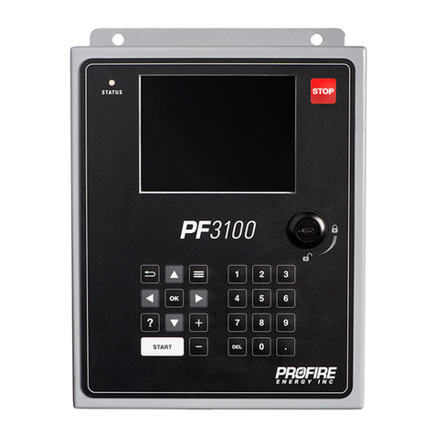
ProFire 1100 User manual

PROFIRE 1100
IGNITION FLAME SAFETY
CONTROLLER
REV 0 October 2009

P R O F I R E C O M B U S T I O N I N C .
2
CAUTIONS
EXPLOSION HAZARD: DO NOT SERVICE UNLESS AREA IS KNO N TO BE NON-
HAZARDOUS
DO NOT OPEN HEN ENERGIZED
SUBSTITUTION OF COMPONENTS MAY IMPAIR THE
SUITABILITY FOR ZONE 2 (Class 1 Division 2)
REPLACEMENT FUSES MUST BE SAND-FILLED
INSTALLATION WARNING
TERMINALS: MUST CONFORM TO THE DIRECTIONS IN THIS
MANUAL
THE UNIT MUST BE PROPERLY CONNECTED TO
EARTH-GROUND FOR EFFECTIVE IONIZATION
OPERATION
ELECTRICAL DEVICES CONNECTED TO THE
CONTROLLER MUST MEET ELECTRICAL STANDARDS
AND BE ITHIN VOLTAGE LIMITS
CONTACT NUMBER
For any questions call:
780-960-5278

P R O F I R E C O M B U S T I O N I N C .
3
Table of Contents
1Features & Specifications....................................................................................................................4
1.1 General Features...................................................................................................................................... 4
1.2 Specifications............................................................................................................................................ 4
1.3 Model Comparison .................................................................................................................................. 6
1.4 Thermocouples......................................................................................................................................... 7
2Installation ...........................................................................................................................................8
2.1 Design Code P&IDs and Wiring Diagrams........................................................................................... 8
2.2 Bill of Materials...................................................................................................................................... 31
2.3 Mounting locations ................................................................................................................................ 33
2.4 System Installation................................................................................................................................. 33
2.5 Pilot & Coil (Optional) .......................................................................................................................... 34
3Keypad & Display.............................................................................................................................36
3.1 Keypad Layout....................................................................................................................................... 36
3.2 Programming Parameters..................................................................................................................... 38
3.3 Messages ................................................................................................................................................. 40
3.4 Error Messages ...................................................................................................................................... 42
4Operations ..........................................................................................................................................43
4.1 Operation Instructions .......................................................................................................................... 43
4.2 Resets ...................................................................................................................................................... 43
4.3 Normal Operation Description ............................................................................................................. 43
4.4 Cause & Effect Diagrams...................................................................................................................... 46
5Troubleshooting .................................................................................................................................49

P R O F I R E C O M B U S T I O N I N C .
4
1 Features & Specifications
1.1 General Features
The following general features are common to all Profire 1100 models:
•Designed for the fire-tube heater industry
•Meets or exceeds all relevant codes and standards
•Easy installation with clearly mar ed component I/O
•Large, easily accessible terminal connections
•Rapid 1.8 second shut-down on flame-out
•DC voltage spar generator
•Ultra-low power design to accommodate solar panel or TEG applications
•Auto relight or manual operation
•Equipped with AVD (Advanced Visual Display) for improved operating functions and signals
•Transient protected and fail-safe circuits
1.2 Specifications
The following specifications are common to all Profire 1100 models:
E N C L O S U R E
Fiberglass
200 x 150 x 100 mm (8" x 6” x 4") overall dimensions
2.3 g (5 lb)
CSA and UL compliant for Class 1 Zone 2 locations
Enclosure type 4, 4X, 12, 13
C I R C U I T B O A R D S
All solid state
CSA compliant for Zone 2 (Class 1, Division 2) locations
I G N I T I O N B A S E A N D C O I L
For non-hazardous mounting area only
P O E R R E Q U I R E M E N T S
+10 to + 28 volts DC (voltage must match solenoid rating)
2.0 amps surge (limited), 0.015 - 2 amps run
P O E R C O N S U M P T I O N
See the Design Code Features table on pg 9 for the power required for each design code.
12V 24V
Controller only, display ON 1.3 W 1.6 W
Controller only, display OFF 0.6 W 0.9 W
System maximum using design codes See pg9 See pg9

P R O F I R E C O M B U S T I O N I N C .
5
T E M P E R A T U R E R A T I N G
-40°C to 55°C
A P P R O V A L S
Zone 2 (Class 1, Division 2) locations approval (CSA 213-92)
Burner Safety approval (CSA 22.2-199) - can be used on B149.3 compliant system
Industrial Process Equipment approval (CSA 14-95)
I N P U T S & O U T P U T S
(4) digital inputs for safety interloc device connections
(4) digital outputs
See Section 1.4 for thermocouple inputs

P R O F I R E C O M B U S T I O N I N C .
6
1.3 Model Comparison
The following table can be used to determine model functionality:
1100 s
(standard)
1100 b1
(bath 1)
1100 b3
(bath 3)
Ionization flame detection
X X X
Thermocouple flame detection
X X
Pilot output off when bath temperature > HH2
X X
Main output off when bath temperature > HH1
X X
Alarm output when fault detected
X X X
Alarm output when bath temperature > HH3
X X
Bath temperature monitored
X X
Separate temperature controller required
X X
Separate over temperature protection required
X
* HH1, HH2 & HH3 are user programmable bath temperature setpoints

P R O F I R E C O M B U S T I O N I N C .
7
1.4 Thermocouples
T E 1 0 1
Type “K”
Measures bath liquid temperature
Primary temperature control device
Connected to an external temperature controller (not included) on Models s & b1
Connected to terminals TC+(yellow) & TC-(red) on card on door on Model b3
20 ga or larger Type “K” extension wire must be used
Provides temperature control
Will not alarm if the wires are shorted together or if an open circuit is detected
A large error will result if either lead is shorted to ground.
T E 1 0 2
Type “K”
Measures bath liquid temperature
Connected to terminals TC+(yellow) & TC-(red) on card on door on Model b1
Connected to terminals TC+(yellow) & TC-(red) on main board on Model b3
Connected to an external temperature controller (not included) on Model s
20 ga or larger Type “K” extension wire must be used
Provides over temperature protection
Not the primary temperature control device
Will alarm if an open circuit is detected
A large error will result if either lead is shorted to ground
T E 3 0 6
Type “K”
Measures pilot temperature
Connected to terminals TC+(yellow) & TC-(red) on main board on Models s & b1
14 ga extension wire without a shield is sufficient
Will fault if an open circuit is detected
A large error will result if either lead is shorted to ground
* TE101 and TE102 may be different elements in the same head of a type “K” thermocouple
* For all thermocouples avoid locating extension wire near high voltage and shield if necessary

P R O F I R E C O M B U S T I O N I N C .
8
2 Installation
2.1 Design Code P&IDs and Wiring Diagrams
The design codes are not exhaustive but only a sample of recommended designs that have been used. Any
design used should be chec ed by a qualified person and approved by the gas authority having jurisdiction at
the site where the system is to be installed. The design used should be clearly mar ed and available to
maintenance and service personnel.
The following tables show and compare the features of each design code for selection and identification
purposes.

P R O F I R E C O M B U S T I O N I N C .
9
Design Code Features
Design
Code Model Burner Size SSV Type Temp Control Type TCV Type Pilot Type Instrument
Gas
Power
Required
301A b1 < 10MM Btuh 2 x electric electric 2- state pneumatic separate separate 30W
301B b1 < 10MM Btuh 2 x electric I/P modulating pneumatic separate separate 15W
301C b1 < 10MM Btuh 2 x electric pneumatic pneumatic separate separate 15W
302A b1 < 10MM Btuh 1 x pneumatic c/w ZSC electric 2- state pneumatic separate separate 10W
302B b1 < 10MM Btuh 1 x pneumatic c/w ZSC I/P modulating pneumatic separate separate 10W
302C b1 < 10MM Btuh 1 x pneumatic c/w ZSC pneumatic pneumatic separate separate 10W
303A b1 < 10MM Btuh 2 x electric + LFSSV electric 2- state LFSSV separate n/a 30W
304A b3 < 1MM Btuh 2 x electric electric 2- state b3 none slipstream n/a 15W
305A b3 < 1MM Btuh 1 x pneumatic c/w ZSC electric 2- state b3 none slipstream separate 15W
306C b1 < 1MM Btuh 2 x electric pneumatic pneumatic slipstream separate 15W

P R O F I R E C O M B U S T I O N I N C .
10
Design Code Advantages & Disadvantages
Design
Code Advantages Disadvantages
301
1) Choice of HI/LO/OFF, electronic or pneumatic modulating temperature control
2) Uses less instrument gas than 302
3) Can be used with remote bath temperature monitoring and setpoint control
4) Less wiring than 302
5) Incorporates triple setpoint HIHI temperature protection
1) Uses an external temperature controller
2) 301A uses more electric power
3) Needs clean and dry instrument gas or air at minimum 35 psig
4) More difficult to install in 6” fire-tubes
302
1) Choice of HI/LO/OFF, electronic or pneumatic modulating temperature control
2) Uses less electric power than 301A
3) Can be used with remote bath temperature monitoring and setpoint control
4) Incorporates triple setpoint HIHI temperature protection
1) Uses an external temperature controller
2) Uses more instrument gas than 301
3) More wiring than in 301
4) Needs clean and dry instrument gas or air at minimum 70 psig
5) More difficult to install in 6” fire-tubes
303
1) No instrument gas needed
2) Suitable for all sour sites
3) Saves cost and GHG emissions
4) Incorporates triple setpoint HIHI temperature protection
1) Limited to HI/LO/OFF temperature control from an external temperature
controller
2) Uses same higher amount of electric power as 301A
3) More difficult to install in 6” fire-tubes
304
1) No instrument gas needed
2) Suitable for all sour sites
3) +/-1°C temperature control deadband built into the BMS controller
4) Reduces pilot freezing problems
5) Allows turning pilot OFF when not needed, then restarting it automatically. (especially for
propane pilots)
6) Ideally suited for 6” fire-tube
7) Save instrument gas cost and GHG emissions
8) Incorporates triple setpoint HIHI temperature protection
1) Limited to HI/Pilot/OFF temperature control.
2) Suitable only for burners up to and including 3” in size and maximum 1 MM Btuh
fuel input.
305
1) +/-1°C HI/pilot/OFF temperature control deadband built into the BMS controller
2) Reduces pilot freezing problems
3) Allows turning pilot OFF when not needed, then restarting it automatically. (especially for
propane pilots)
4) Ideally suited for 6” fire-tube
5) Incorporates triple setpoint HIHI temperature protection
1) Suitable only for burners up to and including 3” in size and maximum 1 MM
Btu/hr fuel input.
2) Needs clean and dry instrument gas or air at minimum 35 psig.
306
1) Uses less instrument gas than 302
2) Can be used with remote bath temperature monitoring and setpoint control
3) Less wiring than 302
4) Incorporates triple setpoint HIHI temperature protection
5) Allows turning pilot OFF when not needed, then restarting it automatically. (especially for
propane pilots)
6) Ideally suited for 6” fire-tube
1) Uses an external temperature controller
2) Needs clean and dry instrument gas or air at minimum 35 psig

P R O F I R E C O M B U S T I O N I N C .
11
FUEL GAS
MAIN
BURNER
PILOT
BURNER
Fire-Tube Heater with
< 10,000,000 BTU/hr (HHV)
Fuel Input
With Electric Safety Shutoff
Valves and HI/LO/PILOT/OFF
Electro-Pneumatic Temperature
Control
PILOT GAS
STACK
STACK
SAMPLE
PORT
ALTERNATE
PILOT FUEL
SUPPLIES
(ONLY ONE
CONNECTED)
DESIGN CODE:
301A

P R O F I R E C O M B U S T I O N I N C .
12

P R O F I R E C O M B U S T I O N I N C .
13
FUEL GAS
MAIN
BURNER
PILOT
BURNER
PILOT GAS
STACK
STACK
SAMPLE
PORT
ALTERNATE
PILOT FUEL
SUPPLIES
(ONLY ONE
CONNECTED)
Fire-Tube Heater with
< 10,000,000 BTU/hr (HHV)
Fuel Input
With Electric Safety Shutoff
Valves and Modulating I/P
Temperature Control
DESIGN CODE:
301B

P R O F I R E C O M B U S T I O N I N C .
14

P R O F I R E C O M B U S T I O N I N C .
15
FUEL GAS
MAIN
BURNER
PILOT
BURNER
PILOT GAS
STACK
STACK
SAMPLE
PORT
ALTERNATE
PILOT FUEL
SUPPLIES
(ONLY ONE
CONNECTED)
Fire-Tube Heater with
< 10,000,000 BTU/hr (HHV)
Fuel Input
With Electric Safety Shutoff
Valves and Modulating
Pneumatic Temperature
Control
DESIGN CODE:
301C

P R O F I R E C O M B U S T I O N I N C .
16

P R O F I R E C O M B U S T I O N I N C .
17
FUEL GAS
MAIN
BURNER
PILOT
BURNER
PILOT GAS
STACK
STACK
SAMPLE
PORT
ALTERNATE
PILOT FUEL
SUPPLIES
(ONLY ONE
CONNECTED)
Fire-Tube Heater with
< 10,000,000 BTU/hr (HHV)
Fuel Input
With Pneumatic Safety
Shutoff Valve and with
HI/LO/PILOT/OFF
Electro-Pneumatic
Temperature Control
DESIGN CODE:
302A

P R O F I R E C O M B U S T I O N I N C .
18

P R O F I R E C O M B U S T I O N I N C .
19
FUEL GAS MAIN
BURNER
PILOT
BURNER
PILOT GAS
STACK
STACK
SAMPLE
PORT
ALTERNATE
PILOT FUEL
SUPPLIES
(ONLY ONE
CONNECTED)
Fire-Tube Heater with
< 10,000,000 BTU/hr (HHV)
Fuel Input
With Pneumatic Safety
Shutoff Valve and with
Modulating I/P Temperature
Control
DESIGN CODE:
302B

P R O F I R E C O M B U S T I O N I N C .
20
Table of contents
Other ProFire Control System manuals
