Cosel LFP100F User manual

3 Temperature Measurement Point LFP-14
5 Ground LFP-17
4 Life expectancy and warranty LFP-16
1 Function LFP-13
2Series Operation and Parallel Operation LFP-14
1.1 Input voltage range
1.2 Inrush current limiting
1.3 Overcurrent protection
1.4 Overvoltage protection
1.5 Thermal protection
1.6 Output voltage adjustment range
1.7 Output ripple and ripple noise
1.8 Isolation
1.9 Reducing standby power
LFP-13
LFP-13
LFP-13
LFP-13
LFP-13
LFP-13
LFP-13
LFP-14
LFP-14
2.1 Series Operation
2.2 Parallel Operation
LFP-14
LFP-14
6 Peak loading LFP-17
7.1 Outline of options
7.2 Others
LFP-18
LFP-20
7 Option and Others LFP-18
Instruction Manual
AC-DC Power Supplies Open Frame/ Enclosed Type
LFP-13
June 26, 2020

1 Function
1.1 Input voltage range
¡The range is from AC85V to AC264V or DC120V to DC370V
(please see SPECIFICATIONS for details).
¡In cases that conform with safety standard, input voltage range is
AC100-AC240V (50/60Hz).
¡
If input value doesn’t fall within above range, a unit may not operate in
accordance with specications and/or start output voltage hunting or fail.
If you need to apply a square waveform input voltage, which is
commonly used in UPS and inverters, please contact us.
¡When the input voltage changes suddenly, the output voltage ac-
curacy might exceed the specication. Please contact us.
¡Operation stop voltage is set at a lower value than that of a stan-
dard version (derating is needed).
-Use Conditions
Output
LFP100F 30W
LFP150F 50W
LFP240F 80W
LFP300F 100W
Input AC50V or DC70V
Duty 1s/30s
1.2 Inrush current limiting
¡An inrush current limiting circuit is built-in.
¡If you need to use a switch on the input side, please select one
that can withstand an input inrush current.
¿ LFP100F, LFP150F
¡Thermistor is used in the inrush current limiting circuit. When you
turn the power ON/OFF repeatedly within a short period of time,
please have enough intervals so that a power supply cools down
before being turned on.
¿ LFP240F, LFP300F
¡Thyristor technique is used in the inrush current limiting circuit.
When you turn power ON/OFF repeatedly within a short period of
time, please have enough intervals so that the inrush current limit-
ing circuit becomes operative.
¡When the switch of the input is turned on, the primary inrush cur-
rent and secondary inrush current will be generated because the
thyristor technique is used for the inrush current limiting circuit.
1.3 Overcurrent protection
¡An overcurrent protection circuit is built-in and activated over
101% of the peak current. A unit automatically recovers when a
fault condition is removed.
Please do not use a unit in short circuit and/or under an overcur-
rent condition.
¡Hiccup Operation Mode
Hiccup operation for overcurrent protection is included in a part of
series. When the overcurrent protection circuit is activated and the
output voltage drops to a certain extent, the output becomes hic-
cup so that the average current will also decrease.
1.4 Overvoltage protection
¡An overvoltage protection circuit is built-in. If the overvoltage pro-
tection circuit is activated, shut down the input voltage, wait more
than 3 minutes and turn on the AC input again to recover the out-
put voltage. Recovery time varies depending on such factors as
input voltage value at the time of the operation.
¡In option -R2, overvoltage protection is removed by toggling ON/
OFF signal of remote control.
Remarks :
Please avoid applying a voltage exceeding the rated voltage to an
output terminal. Doing so may cause a power supply to malfunc-
tion or fail. If you cannot avoid doing so, for example, if you need
to operate a motor, etc., please install an external diode on the
output terminal to protect the unit.
1.5 Thermal protection
¡A thermal protection circuit is built-in.
The thermal protection circuit may be activated under the follow-
ing conditions and shut down the output.
1
When a temperature continue to exceed the values determined
by the derating curve.
2
When a current exceeding the rated current is applied.
3When convection stops.
4When peak load is applied in conditions other than those shown
in Section 5.
If the thermal protection circuit is activated, shut off the input volt-
age and eliminate all the overheating conditions. To recover the
output voltage, have enough time to cool down the unit before
turning on the input voltage again.
1.6 Output voltage adjustment range
¡Adjustment of output voltage is possible by using potentiometer.
1.7 Output ripple and ripple noise
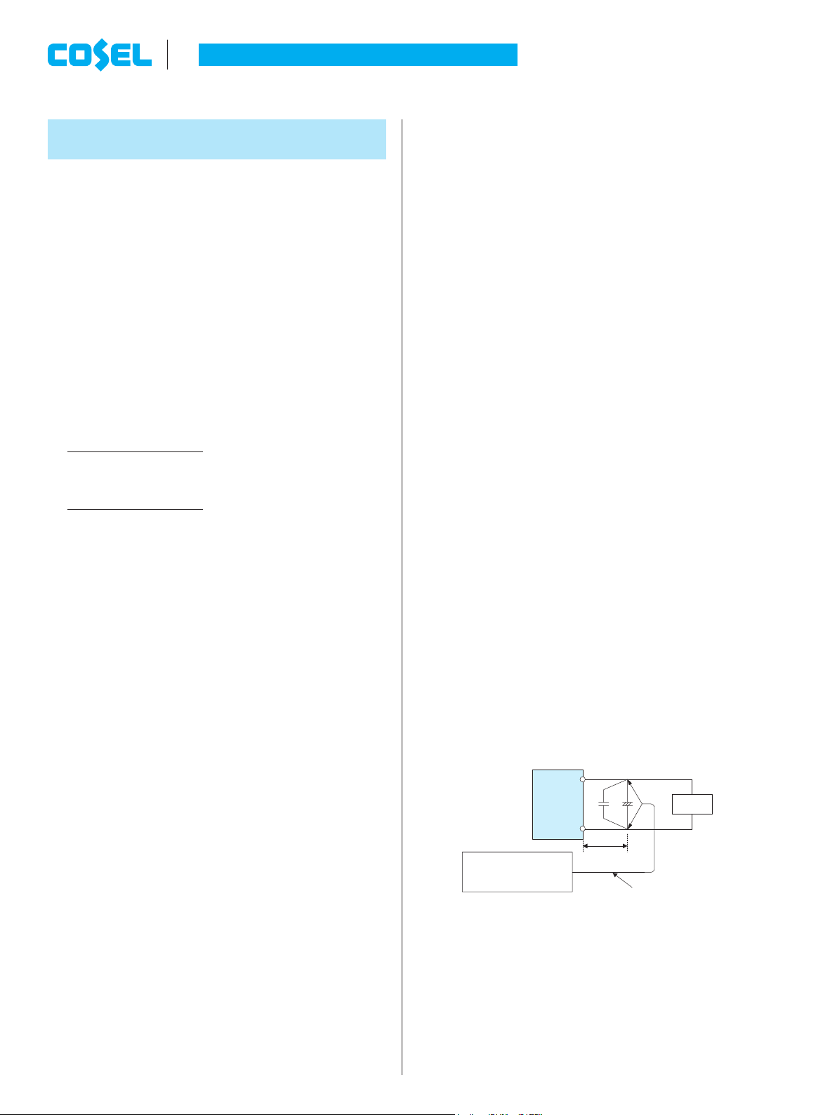
¡Output ripple noise may be inuenced by measurement environ-
ment, measuring method g.1.1 is recommended.
+Vout
-Vout
Load
150mm
C
2
C
1
Osiloscope/
Ripple noise meter
Bw:20MHz
Differential probe
+
C1 : Film capacitor 0.1μF
C2 : Aluminum electrolytic capacitor 22μF
Fig.1.1 Measuring method of Ripple and Ripple Noise
Remarks :
When GND cable of probe with ux of magnetic force from power
supply are crossing, ripple and ripple noise might not measure
correctly.
Please note the measuring environment.
*Please avoid using continuously
for more than 1 second under
above conditions. Doing so
may cause a failure.
AC-DC Power Supplies Open Frame/ Enclosed Type
Instruction Manual
LFP-14 June 26, 2020

¡Even a slight difference in output voltage can affect the balance
between the values of I1and I2.
Please make sure that the value of I3does not exceed the rated
current of a power supply.
I3[the rated current value
3 Temperature
Measurement Point
¡Environment to use it and Installation environment
When using it,it is necessary to radiate heat by the heat of the pow-
er supply.
Table 3.1 - 3.4 shows the relation between the upper limit tempera-
ture (Point A and Point B) and load factors.
Please consider the ventilation so that the convection which is
enough for the whole power supply is provided.
And temperature of Point A and Point B please become lower than
upper limit temperature.
The life expectancy in the upper bound temperature (Point A and
Point B) is three years or more.
Please refer to External View for the position of Point A and Point B.
In case of with Chassis and Cover, please contact our sales ofce
for getting more information.
Remarks:
*Please be careful of electric shock or earth leakage in case of
temperature measurement, because Point A and Point B is live
potential.
*Please refer to 4 if you want to extend the longevity of the life
expectancy.
Table 3.1 Temperatures of Point A, Point B LFP100F-O-Y
Mounting
Method
Cooling
Method
Load factor
Max temperature
Point A[C] Point B[C]
A
Convection
75%<Io[100%
88 86
50%<Io[75%
89 89
0%<Io[50%
89 89
B
Convection
75%<Io[100%
82 81
50%<Io[75%
89 89
0%<Io[50%
89 89
C
Convection
75%<Io[100%
85 86
50%<Io[75%
89 89
0%<Io[50%
89 89
D
Convection
75%<Io[100%
84 76
50%<Io[75%
89 86
0%<Io[50%
89 89
E
Convection
75%<Io[100%
81 89
50%<Io[75%
86 89
0%<Io[50%
87 89
F
Convection
75%<Io[100%
80 77
50%<Io[75%
85 86
0%<Io[50%
88 89
A,B,C,D,E,F Forced air 70%<Io[100%
75 75
0%<Io[70%
75 75
Bad example Good example
Fig.1.2. Example of measuring output ripple and ripple noise
1.8 Isolation
¡For a receiving inspection, such as Hi-Pot test, gradually increase
(decrease) the voltage for the start (shut down). Avoid using Hi-
Pot tester with the timer because it may generate voltage a few
times higher than the applied voltage, at ON/OFF of a timer.
1.9 Reducing standby power
¡As for option -R2, reducing standby power is possible by OFF sig-
nal of the remote control.
Please refer to instruction manual 7.1.
2 Series Operation and
Parallel Operation
2.1 Series Operation
¡You can use a power supply in series operation. The output cur-
rent in series operation should be lower than the rated current of a
power supply with the lowest rated surrent among power supplies
that are serially connected. Please make sure that no surrent ex-
ceeding the rated current ows into a power supply.
Load
Power
Supply
+
-
+
-
Power
Supply
LoadLoad
Power
Supply
+
-
+
-
Power
Supply
Fig.2.1 Examples of connecting in series operation
2.2 Parallel Operation
¡Parallel operation is not possible.
¡Redundancy operation is available by wiring as shown below.
I2
I1I3
-
+
+
-
Load
Power
Supply
Power
Supply
Fig.2.2 Example of redundancy operation
AC-DC Power Supplies Open Frame/ Enclosed Type
Instruction Manual
LFP-15
June 26, 2020

Table 3.4 Temperatures of Point A, Point B, Point C, Point D
LFP300F-O-TY
Mounting
Method
Cooling
Method
Load factor
Max temperature
Point A[C] Point B[C] Point C[C] Point D[C]
A
Convection
80%<Io[100%
70 86
60%<Io[80%
75 88
Io[60%
79 89
B
Convection
80%<Io[100%
59 68
60%<Io[80%
68 76
Io[60%
76 86
C
Convection
80%<Io[100%
70 84
60%<Io[80%
77 89
Io[60%
80 89
D
Convection
80%<Io[100%
57 64
60%<Io[80%
65 73
Io[60%
77 83
E
Convection
80%<Io[100%
60 79
60%<Io[80%
66 81
Io[60%
76 88
A,B,C,D and E Forced air 50%<Io[100%
75 75 85 85
Io[50%
75 75 85 85
4 Life expectancy and
warranty
¡Life Expectancy.
Table 4.1 Life Expectancy
(
LFP100F-O-Y
)
Mounting
Method
Cooling
Method
Average ambient
temperature (year)
Life Expectancy
Io[75%
75%<Io[100%
A Convection Ta = 40Cor less 10years or more 10years or more
Ta = 50C10years or more 9years
B
Convection Ta = 35Cor less 10years or more 10years or more
Ta = 45C10years or more 10years or more
C
Convection Ta = 35Cor less 10years or more 10years or more
Ta = 45C10years or more 9years
D, E, F
Convection Ta = 25Cor less 10years or more 10years or more
Ta = 35C10years or more 7years
A,B,C,D,E,F
Forced air Ta = 60C5years 3years
Table 4.2 Life Expectancy
(
LFP150F-O-Y
)
Mounting
Method
Cooling
Method
Average ambient
temperature (year)
Life Expectancy
Io[75%
75%<Io[100%
A Convection Ta = 40Cor less 10years or more 10years or more
Ta = 50C10years or more 8years
B
Convection Ta = 35Cor less 10years or more 10years or more
Ta = 45C10years or more 10years or more
C
Convection Ta = 35Cor less 10years or more 10years or more
Ta = 45C10years or more 6years
D, E, F
Convection Ta = 20Cor less 10years or more 10years or more
Ta = 30C10years or more 10years or more
A,B,C,D,E,F
Forced air Ta = 60C5years 3years
Table 3.2 Temperatures of Point A, Point B LFP150F-O-Y
Mounting
Method
Cooling
Method
Load factor
Max temperature
Point A[C] Point B[C]
A
Convection
75%<Io[100%
84 81
50%<Io[75%
89 89
0%<Io[50%
89 89
B
Convection
75%<Io[100%
83 81
50%<Io[75%
89 89
0%<Io[50%
89 89
C
Convection
75%<Io[100%
87 85
50%<Io[75%
89 89
0%<Io[50%
89 89
D
Convection
75%<Io[100%
83 65
50%<Io[75%
89 75
0%<Io[50%
89 85
E
Convection
75%<Io[100%
77 86
50%<Io[75%
81 89
0%<Io[50%
86 89
F
Convection
75%<Io[100%
78 76
50%<Io[75%
82 82
0%<Io[50%
89 89
A,B,C,D,E,F Forced air 70%<Io[100%
75 75
0%<Io[70%
75 75
Table 3.3 Temperatures of Point A, Point B, Point C LFP240F-O-Y
Mounting
Method
Cooling
Method
Load factor
Max temperature
Point A[C] Point B[C] Point C[C]
A
Convection
75%<Io[100%
89 82
50%<Io[75%
89 88
0%<Io[50%
89 89
B
Convection
75%<Io[100%
85 74
50%<Io[75%
89 82
0%<Io[50%
89 89
C
Convection
75%<Io[100%
89 83
50%<Io[75%
89 88
0%<Io[50%
89 89
D
Convection
75%<Io[100%
88 74
50%<Io[75%
89 85
0%<Io[50%
89 89
E
Convection
75%<Io[100%
89 86
50%<Io[75%
89 89
0%<Io[50%
89 89
F
Convection
75%<Io[100%
79 68
50%<Io[75%
86 77
0%<Io[50%
89 89
A,B,C,D,E,F Forced air 70%<Io[100%
75 75 85
0%<Io[70%
75 75 85
AC-DC Power Supplies Open Frame/ Enclosed Type
Instruction Manual
LFP-16 June 26, 2020

Table 4.3 Life Expectancy
(
LFP240F-O-Y
)
Mounting
Method
Cooling
Method
Average ambient
temperature (year)
Life Expectancy
Io[75%
75%<Io[100%
A Convection Ta = 40Cor less 10years or more 10years or more
Ta = 50C8years 5years
B
Convection Ta = 35Cor less 10years or more 10years or more
Ta = 45C9years 6years
C
Convection Ta = 25Cor less 10years or more 10years or more
Ta = 35C10years or more 6years
D, E
Convection Ta = 20Cor less 10years or more 10years or more
Ta = 30C10years or more 8years
F
Convection Ta = 25Cor less 10years or more 10years or more
A,B,C,D,E,F
Forced air Ta = 60C5years 3years
Table 4.4 Life Expectancy
(
LFP300F-O-TY
)
Mounting
Method
Cooling
Method
Average ambient
temperature (year)
Life Expectancy
Io[75%
75%<Io[100%
A Convection Ta = 30Cor less 10years or more 10years or more
Ta = 40C10years or more 10years or more
B, C
Convection Ta = 20Cor less 10years or more 10years or more
Ta = 30C10years or more 9years
D, E
Convection Ta = 25Cor less 10years or more 7years
A,B,C,D,E
Forced air Ta = 50C5years 3years
¡Warranty
Table 4.5 Warranty
(
LFP100F-O-Y
)
Mounting
Method
Cooling
Method
Average ambient
temperature (year)
Warranty
Io[75%
75%<Io[100%
A Convection Ta = 40Cor less 5years 5years
Ta = 50C5years 3years
B Convection Ta = 35Cor less 5years 5years
Ta = 45C5years 3years
C Convection Ta = 35Cor less 5years 5years
Ta = 45C5years 3years
D, E, F
Convection Ta = 25Cor less 5years 5years
Ta = 35C5years 3years
A,B,C,D,E,F
Forced air Ta = 60C5years 3years
Table 4.6 Warranty
(
LFP150F-O-Y
)
Mounting
Method
Cooling
Method
Average ambient
temperature (year)
Warranty
Io[75%
75%<Io[100%
A Convection Ta = 40Cor less 5years 5years
Ta = 50C5years 3years
B Convection Ta = 35Cor less 5years 5years
Ta = 45C5years 3years
C Convection Ta = 35Cor less 5years 5years
Ta = 45C5years 3years
D, E, F
Convection Ta = 20Cor less 5years 5years
Ta = 30C5years 3years
A,B,C,D,E,F
Forced air Ta = 60C5years 3years
Table 4.7 Warranty
(
LFP240F-O-Y
)
Mounting
Method
Cooling
Method
Average ambient
temperature (year)
Warranty
Io[75%
75%<Io[100%
A Convection Ta = 40Cor less 5years 5years
Ta = 50C5years 3years
B Convection Ta = 35Cor less 5years 5years
Ta = 45C5years 3years
C Convection Ta = 25Cor less 5years 5years
Ta = 35C5years 3years
D, E
Convection Ta = 20Cor less 5years 5years
Ta = 30C5years 3years
F Convection Ta = 25Cor less 5years 3years
A,B,C,D,E,F
Forced air Ta = 60C5years 3years
Table 4.8 Warranty
(
LFP300F-O-TY
)
Mounting
Method
Cooling
Method
Average ambient
temperature (year)
Warranty
Io[75%
75%<Io[100%
A Convection Ta = 30Cor less 5years 5years
Ta = 40C5years 3years
B, C Convection Ta = 20Cor less 5years 5years
Ta = 30C5years 3years
D, E
Convection Ta = 25Cor less 5years 3years
A,B,C,D,E
Forced air Ta = 50C5years 3years
5 Ground
¡When installing the power supply with your unit, ensure that the
input FG terminal of CN1 or mounting hole FG is connected to
safety ground of the unit.
6 Peak loading
¡Peak load is possible to draw as below.
0t[sec]
t
1
t
2
l
l
O
P
l
ave
: average curren
t
: peak current
Output current [A]
t1[10 [sec], lave =
IPt1+IOt2
t1+t2[rated current,
t1
t1+t2[0.40 (Refer to below chart)
Duty is depended on peak load, refer to below chart.
1AC100V 2AC200V
Duty [%]
10
0
20
40
Peak Wattage[W]
100 160 200
LFP100F
AC-DC Power Supplies Open Frame/ Enclosed Type
Instruction Manual
LFP-17
June 26, 2020

Duty [%]
10
0
20
40
Peak Wattage[W]
150 240 300
LFP150F
1AC100V 2AC200V
3
Duty [%]
10
0
15
20
40
Peak Wattage[W]
240 360 480
LFP240F
Forced air
1AC100V 2AC200V
Duty [%]
40
1AC100V 2AC200V
0360300 510 540 600
10
Peak Wattage[W]
LFP300F
Fig.6.1 Derating of peak loading
7 Option and Others
7.1 Outline of option
¿ -C
-Option -C models have coated internal PCB for better moisture
resistance.
¿ -G
-Option -G models are low leakage current type.
-Differences from standard versions are summarized in Table 7.1.
Table 7.1 Low leakage current type
Leakage Current
(AC240V 60Hz) 0.15mA max
Conducted Noise N/A
Output Ripple Noise Please contact us for details about
Ripple Noise
*This is the value that measured on measuring board with capaci-
tor of 22μF at 150mm from output connector.
Measured by 20MHz oscilloscope or Ripple-Noize meter (Equivalent
to KEISOKU-GIKEN:RM-103).
¿ -J (LFP300F)
-Option -J models, the input and output connector are changed
to EP connectors (Mfr. Tyco Electronics).
-The appearance in option -J models are defferent from the stan-
dard untis. Please contact us about the detail.
¡LFP300F
I/O Connector Mating connector Terminal
CN1 7-1565036-6 1-1123722-8 Chain 1123721-1
Loose 1318912-1
CN2 1-1123723-6 1-1123722-6 Chain 1123721-1
Loose 1318912-1
CN3 1-1123723-7 1-1123722-7 Chain 1123721-1
Loose 1318912-1
(Mfr:Tyco Electeonics)
¿ -J1
-Option -J1 models, the Input and Output connector is VH con-
nectors (Mfr. J.S.T.).
-LFP300F appearance of option -J1 models are defferent from
the standard appearance. Please contact us about the detail.
¡LFP100F
I/O Connector Mating connector Terminal
CN1 B3P5-VH VHR-5N Chain SVH-21T-P1.1
Loose BVH-21T-P1.1
CN2 B8P-VH VHR-8N Chain SVH-21T-P1.1
Loose BVH-21T-P1.1
(Mfr:J.S.T)
¡LFP150F,LFP240F
I/O Connector Mating connector Terminal
CN1 B3P5-VH VHR-5N Chain SVH-21T-P1.1
Loose BVH-21T-P1.1
CN2 B6P-VH VHR-6N Chain SVH-21T-P1.1
Loose BVH-21T-P1.1
CN3 B7P-VH VHR-7N Chain SVH-21T-P1.1
Loose BVH-21T-P1.1
(Mfr:J.S.T)
¡LFP300F
I/O Connector Mating connector Terminal
CN1
B6P(8-3.6)-VH
VHR-8N Chain SVH-21T-P1.1
Loose BVH-21T-P1.1
CN2 B6P-VH VHR-6N Chain SVH-21T-P1.1
Loose BVH-21T-P1.1
CN3 B7P-VH VHR-7N Chain SVH-21T-P1.1
Loose BVH-21T-P1.1
(Mfr:J.S.T)
AC-DC Power Supplies Open Frame/ Enclosed Type
Instruction Manual
LFP-18 June 26, 2020

¿ -S--SN
--S indicates a type with chassis, and -SN indicates a type with
chassis and cover (Refer to external view).
Please contact us about the detail of derating curve.
-Please contact us about the detail of LFP300F.
¿ -SNF (LFP300F-24-TY)
-In option -SNF, the cover, chassis and cooling fan are added.
-The appearance of option -J and -J1 models are defferent from
the of standard appearance. Please contact us about the detail.
-Oil and other chemical liquid splashing environment may cause
the performance degradation and failure.
¿ -R
-You can control output ON/OFF remotely in Option -R models.
To do so, connect an external DC power supply and apply a
voltage to a remote ON/OFF connector, which is available as
option.
Model Name
Built-in
Resistor
Ri [ W]
Voltage between RC (+)
and RC (-) [V]
Input
Current
[mA]
Output ON Output OFF
LFP100F, LFP150F
LFP240F, LFP300F 780 4.5 - 12.5 0 - 0.5 20max
Ri
RC (-)
RC (+)
2
1
*1
RSW
External Power
Source
Remote ON/OFF connector (Optional)
Input Current
Inside of a Power
Supply
Fig.7.1 Example of using a remote ON/OFF circuit
-
Dedicated harnesses are available for your purchase. Please
see Optional Parts for details.
*1 If the output of an external power supply is within the range
of 4.5 - 12.5V, you do not need a current limiting resistor R. If
the output exceeds 12.5V, however, please connect the cur-
rent limiting resistor R.
To calculate a current limiting resistance value, please use the fol-
lowing equation.
R[W]= Vcc-(1.1+RiX0.005)
0.005
*
Please wire carefully. If you wire wrongly, the internal components
of a unit may be damaged.
¡Remote ON/OFF circuits (RC+ and RC-) are isolated from input,
output and FG.
¿ -R2
-The usege is the same as option -R, please refer to Option -R.
-Reducing standby power is possible by OFF signal of the re-
mote control.
-Start up time by ON signal in remote control is 350ms(typ).
-The latch condition in overvoltage protection is removed by tog-
gling ON/OFF signal of remote control.
-Standby power
LFP100F, LFP150F, LFP240F
0.2Wtyp (AC100V), 0.7Wtyp (AC200V)
LFP300F
0.25Wtyp (AC100V), 1.1Wtyp (AC200V)
¿ -T (LFP240F, LFP300F)
-Option -T models have vertically positioned screws on a termi-
nal block.
-Please contact us for details about appearance.
FG
AC (N)
AC (L)
-V
+V
Fig.7.2 Example of option -T
¡The screw can be held to terminal block by inserting and lifting the
screwdriver from the side of terminal block.
+ screwdriver
terminal block
screw
f5.5MAX
Fig.7.3 lifting method
¿ -T1 (LFP300F)
-Option -T1 models have horizontally positioned screws on a ter-
minal block.
-Please contact us for details about appearance.
FG
AC (N)
AC (L)
-V
+V
Fig.7.4 Example of option -T1
AC-DC Power Supplies Open Frame/ Enclosed Type
Instruction Manual
LFP-19
June 26, 2020

¿ -U1 (LFP240F, LFP300F)
¡By connecting the external capacitor unit CR-HUT(optional parts),
Hold-up time is extensible.
Output power [W]
Hold-up time [ms]
External
capacitor
unit model
CR-HUT502-
2
CR-HUT282-
2
CR-HUT721-
1
CR-HUT241-
1
0 50 100 150 200 250 300
10
100
1,000
10,000
Fig.7.5 Hold-up time by LFP240F-O-U1Y(Reference data).
Output power [W]
Hold-up time [ms]
External
capacitor
unit model
CR-HUT502-
2
CR-HUT282-
2
CR-HUT721-
1
CR-HUT241-
1
0 50 100150200250 300 350
10
100
1,000
10,000
Fig.7.6 Hold-up time by LFP300F-O-TU1Y(Reference data).
¡Connection method
Power supply
VC(+) VC(
-
)
VC(+) VC(
-
)
d=5 - 30mm
Harness H-IN-23
(sell separately)
External capacitor unit
(CR-HUT)
CN1
Fig.7.7 Connection method
¿
Caution
(1) Distance between the external capacitor unit and power supply
unit must be secured more than 5mm.
(2) It must be 30mm or less, since the noise is generated from the
wire which is connecting the external capacitor unit and power
supply. And, it is necessary to twist the wire as short as possible.
(3) It is necessary to use wires which rated voltage is 600V or more.
(4) It must be used with the external capacitor unit (CR-HUT).
(5) For more information about the external capacitor unit and har-
ness, please refer to Optional Parts.
7.2 Others
¡This power supply is the rugged PCB type. Do not drop conduc-
tive objects in the power supply.
¡At light load, there remains high voltage inside the power supply
for a few minutes after power OFF.
So, at maintenance, take care about electric shock.
¡This power supply is manufactured by SMD technology. The
stress to PCB like twisting or bending causes the defect of the
unit, so handle the unit with care.
-Tighten all the screws in the screw hole.
-Install it so that PCB may become parallel to the clamp face.
-Avoid the impact such as drops.
¡While turning on the electricity, and for a while after turning off,
please don’t touch the inside of a power supply because there are
some hot parts in that.
¡When a mass capacitor is connected with the output terminal (load
side), the output might become the stop or an unstable operation.
Please contact us for details when you connect the capacitor.
AC-DC Power Supplies Open Frame/ Enclosed Type
Instruction Manual
LFP-20 June 26, 2020
This manual suits for next models
3
Table of contents
Other Cosel Power Supply manuals

Cosel
Cosel RBC200F User manual

Cosel
Cosel TUNS1200F Series Instructions for use

Cosel
Cosel SPLFA30F User manual

Cosel
Cosel KHEA30F User manual

Cosel
Cosel PLA100F User manual

Cosel
Cosel STA5000T-R User manual

Cosel
Cosel PCA Series User manual

Cosel
Cosel FETA2500B User manual

Cosel
Cosel GHA300F User manual

Cosel
Cosel UAF500S Series User manual