Diesse VES-MATIC EASY User manual

SERVICE MANUAL
Version SW 2.xx
Rev.1.1 of 15/04/2017
Automatic instrument for determining the erythrocyte sedimentation rate (ESR)
(Patented)
(Diagnostic Device -IVDD 98/79)
Diagnostica Senese S.p.A

Service Manual
Rev.1.1 of 15/04/2017 ii [2/76]
LIST OF REVISIONS
MANUAL
REVISIONS
DESCRIPTION OF MODIFICATION
APPR.
1.0
of
06/2007
Official Version
1.1
of
04/2017
Added assembly note in the Reassembly
procedure, par. 2.4.
MODELS
This manual applies to the following Ves Matic Easy model:
DIESSE Code
Model description
10376
VES MATIC EASY CE/CSA
TECHNICAL ASSISTANCE
DIESSE DIAGNOSTICA SENESE SpA - CUSTOMER CARE
Via del Pozzo 5, 53035 Monteriggioni (SI), Italy
Tel. ++39 0577 319556 Fax. ++39 0577 319020
e-mail: customerca[email protected]t
The information contained in this manual is subject to modifications without prior notice. No part of this
manual may be reproduced in any electronic or mechanical form for any purpose whatsoever without
the written authorization of DIESSE DIAGNOSTICA SENESE S.p.A.
Printed in JUNE 2007. (Total pages: 76).
Standards applied in this document:
UNI EN 591 II Edition (November 2001)
CEI EN 61010-1 II Edition File 6290 (November 2001)

Service Manual
[3/76] iii Rev.1.1 of 15/04/2017
CONTENTS
1. GENERAL DESCRIPTION OF THE INSTRUMENT.........................................................1
1.1. OVERALL VIEW OF THE UNIT..............................................................................2
1.2. TECHNICAL SPECIFICATIONS.............................................................................3
1.3. CONTENT AND PACKAGE DIMENSIONS............................................................3
1.4. SHUTTING DOWN AND SHIPPING.......................................................................4
2. DISASSEMBLY PROCEDURE (AND REASSEMBLY)....................................................5
2.1. GRAPHICS.............................................................................................................6
2.2. PRELIMINARY TASKS ASSIGNED TO THE TECHNICAL SERVICE ...................6
2.3. EQUIPMENT / INSTRUMENTATION REQUIRED .................................................7
2.4. DISASSEMBLY AND REASSEMBLY PROCEDURES...........................................7
3. CALIBRATIONS AND PERIODICAL CHECKS ...............................................................8
3.1. PROCEDURE FOR CALIBRATING THE VES MATIC EASY FOLLOWING
DISASSEMBLY OR PERIODIC CHECKS.........................................................................9
3.1.1. ACCESS TO THE SERVICE MENU.......................................................................9
3.1.2. TEST STATUS OF SENSORS & HOME PHOTOCELL .......................................11
3.1.3. MOTOR TEST ......................................................................................................11
3.1.4. SENSOR TEST.....................................................................................................12
3.1.5. SENSOR CALIBRATION......................................................................................12
3.1.6. BARCODE TEST..................................................................................................13
3.1.7. ADJUSTING THE CARRIAGE STROKE READING.............................................14
3.1.8. CONFIGURATION OF ID No................................................................................14
3.1.9. PRINT SETTINGS................................................................................................14
3.1.10. CONFIGURATION OF TEST MODE................................................................15
3.1.11. ANALYSIS COUNTER .....................................................................................16
3.1.12. PRINT ERRORS...............................................................................................16
3.1.13. CYCLES TEST.................................................................................................16
3.2. CLEANING THE PRINTER HEAD........................................................................17
4. LEARNING ABOUT THE UNIT- DESCRIPTION OF THE MAIN MODULES.................18
4.1. LEARNING ABOUT THE UNIT.............................................................................19
4.2. CPU BOARD ........................................................................................................20
4.2.1. Description of the module.......................................................................................................20
4.2.2. Applicable documentation.......................................................................................................20
4.2.3. Access to single modules .......................................................................................................21
4.3. VES EASY CONNECTION BOARD .....................................................................21
4.3.1. Description of the module.......................................................................................................21
4.3.2. Applicable documentation.......................................................................................................21

Service Manual
Rev.1.1 of 15/04/2017 iv [4/76]
4.3.3. Access to single modules .......................................................................................................21
4.4. VES10/ESAY SENSOR AND HOME PHOTOCELL READING BOARDS............22
4.4.1. Description of the module.......................................................................................................22
4.4.2. Applicable documentation.......................................................................................................22
4.4.3. Access to single module.........................................................................................................22
4.5. PRINTER INTERFACE MODULE.........................................................................23
4.5.1. Description of the module.......................................................................................................23
4.5.2. Applicable documentation.......................................................................................................23
4.5.3. Access to single module.........................................................................................................23
5. TROUBLE-SHOOTING FOR SINGLE FAULTS.............................................................24
5.1. ANALYSIS OF THE FAULTS ...............................................................................25
5.2. PROBLEMS/FAULTS AT START-UP...................................................................25
5.2.1. The unit fails to turn on .........................................................................................25
5.2.2. The unit turns on / Display KO-Keyboard KO .......................................................26
5.2.2. The unit turns on / Initial reset KO.........................................................................26
5.2.3. The unit turns on / Printer KO ...............................................................................29
5.2.4. The unit turns on / External connections KO.........................................................31
5.3. TROUBLESHOOTING DURING THE OPERATING PHASE ...............................32
6. EXPLODED DRAWINGS AND COMPONENT LISTS FOR UNITS................................34
6.1. VES MATIC EASY UNIT (30003800) ...................................................................35
Exploded drawing..............................................................................................................................35
Component list ..................................................................................................................................36
List of Accessories & Optionals ........................................................................................................36
6.2. ANALYSIS HANDLING UNIT- (30208221)...........................................................37
Exploded drawing..............................................................................................................................37
Component list ..................................................................................................................................38
6.3. VES MATIC EASY PRINTER UNIT (30208230)...................................................39
Exploded drawing..............................................................................................................................39
Component list ..................................................................................................................................40
6.4. INTERCONNECTION DIAGRAM/ ELECTRICAL CONNECTIONS LAYOUT.......41
Component list: WIRING...................................................................................................................42
7. ELECTRICAL DIAGRAMS AND BOARD LAYOUTS ....................................................43
7.1. VES MATIC EASY CPU BOARD..........................................................................44
Layout Code 30119871.....................................................................................................................44
Electrical diagram Code 20103292 (Total pages 3) .........................................................................45
7.2. VES MATIC EASY CONNECTION BOARD .........................................................48
Layout Code 30120011.....................................................................................................................48
Electrical diagram CODE 20103311.................................................................................................49
7.3. VES MATIC EASY FRONT/REAR READ SENSOR BOARD...............................50
Layout Code 30119990.....................................................................................................................50
Layout Code 30120000.....................................................................................................................51
Electrical diagram Code 20103300...................................................................................................52

Service Manual
[5/76] v Rev.1.1 of 15/04/2017
7.4. WIRED PHOTOCELL BOARD .............................................................................53
Layout code 30121610......................................................................................................................53
7.5. BOARD PRINTER WT01 SMALL.........................................................................54
Layout CODE 30111340...................................................................................................................54
Electrical diagram CODE 20102462.................................................................................................55
ATTACHMENT A: EXTERNAL CONNECTIONS....................................................................1
1. GENERAL SPECIFICATIONS FOR CONNECTING TO A BARCODE READER...2
2. GENERAL SPECIFICATIONS FOR CONNECTION TO A HOST COMPUTER.....3
3. SPECIFICATIONS OF THE ASYNCHRONOUS SERIAL COMMUNICATION
PROTOCOL......................................................................................................................3
4. VES EASY SERIAL COMMANDS AND PARAMETER FORMAT ..........................4
ATTACHMENT B: UPGRADE SOFTWARE ............................................................................8
1. INSTALLING THE PROGRAMMING SOTWARE ‘WinBootPrg’ .............................9
2. COPYING THE FILE TO TRANSFER TO THE UNIT...........................................10
3. PROGRAMMING PROCEDURE / UPGRADE SOFTWARE ................................11
FORMS......................................................................................................................................14

Service Manual
Rev.1.1 of 15/04/2017 vi [6/76]

Service Manual
[7/76] 1 Rev.1.1 of 15/04/2017
1. GENERAL DESCRIPTION OF THE INSTRUMENT
1.1. OVERALL VIEW OF THE UNIT..................................................................................................2
1.2. TECHNICAL SPECIFICATIONS.................................................................................................3
1.3. CONTENT AND PACKAGE DIMENSIONS ................................................................................3
1.4. SHUTTING DOWN AND SHIPPING...........................................................................................4

Service Manual
Rev.1.1 of 15/04/2017 2 [8/76]
1.1. OVERALL VIEW OF THE UNIT
Fig. 1-1
Legend:
1) Cuvette-holder with 10 numbered positions
2) Display
3) Keyboard
4) Printout-Paper slit
5) EXTERNAL BARCODE connector
(External Barcode Reader)
6) USB connector
7) ON/OFF switch
8) DC IN socket for 9Vdc power supply
9) Paper-holder compartment

Service Manual
[9/76] 3 Rev.1.1 of 15/04/2017
1.2. TECHNICAL SPECIFICATIONS
Power supply
9Vdc@2A
Dimensions
143 x 218 x146 mm ( w x h x d )
Weigh
1.2 Kg
Ambient temperature
Operational
from +15 to +35°C
Storage
from + 5°C to + 45°C
Relative humidity tolerance
from 20 to 80% without condensation
Central unit
AVR ATMEGA128-16AC microprocessor
Display
LCD with Backlight, 16 characters x 1 row
Cuvette-holder
With 10 numbered recesses for the relative cuvettes
Optical unit
10 pairs of opto-electronic elements in solid state (photodiode +
phototransistor).
Printer
Alphanumeric with thermal paper 58 mm wide, 36 characters per line,
speed: 20 mm/sec.
Interfaces
USB
Class
II
Device safety
CEI EN 61010-1 (Ed.2001-11);
CAN/CSA-C22.2 Nr.61010-1-04 (Ed.2004-07);
UL61010-1 (Ed.2004-07).
EMC
CEI EN61326 (ED.2004-08)
Installation category
II
Safety requirements and functional performances of the instrument are not assured if
you use a different power supply from the one supplied in the package.
1.3. CONTENT AND PACKAGE DIMENSIONS
MATERIAL SUPPLIED WITH THE INSTRUMENT
The VESMATIC EASY is supplied with the following material:
▪1 Operating Manual [English] [Order Code: P30600650]
▪1 “VESMATIC EASY”CD [Order Code: P30650050]
▪1 Power Supply 9Vdc 2A Mod. ES18A09-P1J [MeanWell] [Order Code: P21440380]
▪1 Power Cord 3x0.75 L=2m Plug SCHUKO 90° - C13 [Order Code: P21890040]
▪1 Power Cord SVT L=2m Male Plug USA / Female Plug VDE ‘UL’ [Order Code: P21890370]
▪1 USB 1.1 A-B M/M Cable (1.5mt) [Order Code: P21890360]
▪1 Thermal Roller Paper for Printer [Order Code: P12300000]
▪1 Packing-list
▪1 Final Inspection Report
▪1 Guarantee Certificate (for CAN/USA Market)

Service Manual
Rev.1.1 of 15/04/2017 4 [10/76]
Package dimensions
WIDTH (box)
cm
30
HEIGHT (box)
cm
19
DEPTH (box)
cm
28
GROSS WEIGHT
g
2400
PACKAGING WEIGHT
g
400
Do not throw away the original packaging in case of further transportation of the instrument in
the future.
1.4. SHUTTING DOWN AND SHIPPING
Before shutting down and shipping the instrument it is recommended carrying out the
following sanitising procedure:
A) The instrument must be turned off and cleaned internally of all residues or spillage with a liquid
detergent and left to dry.
B) Use one of the ready-to-use spray cans of isopropyl alcohol available on the market.
C) Spray well on the sample-holder.
D) Leave turned off for at least one hour before beginning a new work cycle or any other type of
operation on the instrument.
Instrument maybe damaged if dropped.
SHIPPING
1. Insert the instrument, the power supply unit and accessories into the
box.
2. Close the box.
If the instrument is being shipped to the manufacturer for repairs, affix a copy of the “Fault Report”form
(contained in this document) to the outside of the box.

Service Manual
[11/76] 5 Rev.1.1 of 15/04/2017
2. DISASSEMBLY PROCEDURE (and reassembly)
2.1. GRAPHICS.................................................................................................................................6
2.2. PRELIMINARY TASKS ASSIGNED TO THE TECHNICAL SERVICE........................................6
2.3. EQUIPMENT / INSTRUMENTATION REQUIRED......................................................................7
2.4. DISASSEMBLY AND REASSEMBLY PROCEDURES...............................................................7

Service Manual
Rev.1.1 of 15/04/2017 6 [12/76]
2.1. GRAPHICS
Legend of graphic symbols used on the Instrument [Standard applied: EN980:2003].
Instrument satisfying requirements of european directive on in vitro diagnostic medical
devices (98/79/EC).
In vitro diagnostic medical device.
USC
®
Instrument satisfying CSA standards for the Canadian and Usa market
Date of manufacturing of the unit.
Serial number of the unit.
Manufactured by.
Legend of Electrical and Safety symbols used on the instrument:
Attention, read the manual and observe the relative safety symbols.
WEEE: Disposal of Waste Electrical and Electronic Equipment - At the end of its life, this
instrument should be disposed of according to separate waste collection provisions
[2002/96/EC, 2003/108/EC]
Legend of Symbols used on the document:
WARNING, potential hazard of personal injury, all the conditions indicated in the associated
text must be stored and understood before proceeding.
WARNING, potential danger of damaging the instrument all the conditions indicated in the
associated text must be known and understood before proceeding.
ATTENTION, important information.
BIOHAZARD, danger of contamination with potentially infected substance.
2.2. PRELIMINARY TASKS ASSIGNED TO THE TECHNICAL SERVICE
Before any type of operation on the instrument:
a) TURN OFF THE ON/OFF SWITCH ON THE UNIT.
b) DISCONNECT THE INSTRUMENT FROM THE POWER SUPPLY IN ORDER TO
PREVENT RISK OF CONTACT WITH ANY ENERGISED ELECTRICAL OR
MECHANICAL PARTS.
FAILURE TO OBSERVE THESE INSTRUCTIONS SHALL RELEASE THE MANUFACTURER OF THE
VESMATIC EASY FROM ALL LIABILITY.

Service Manual
[13/76] 7 Rev.1.1 of 15/04/2017
2.3. EQUIPMENT / INSTRUMENTATION REQUIRED
-Multimetre - Mod.Fluke 8010A or equivalent.
-Set of screwdrivers.
-Set socket-head spanners.
-5.5mm Plug socket spanner.
-10 Cuvettes containing 2ml Latex [*]
-10 Cuvettes containing 3ml Latex [*]
[*: Diesse Code 10406: 1 cuvette with 2ml Latex + 1 cuvette with 3ml Latex]
2.4. DISASSEMBLY AND REASSEMBLY PROCEDURES
Disassembly procedure
a) Follow the instructions in paragraph 2.2 points a) and b).
b) Remove the lower lid code 10602170 (Pos.007-Tab.300033800), lift up the printing head (see
point 3.2) and remove the paper from the printer.
c) Use a screwdriver to unscrew the 4 screws M3x12 (Pos.203-Tab.30003800) anchoring the front
panel code 30208601 (Pos.002-Tab.30003800) to the rear panel code 30208611 (pos.001-
Tab.30003800).
d) Ease out the upper lid (Pos.006-Tab.30003800) anchored to the side panels by the springs on
the moulds.
d) Disconnet the wiring attached to the Ves-Matic Easy Connection Board (Pos.101-Tab.30003800)
in order to access the electrical and mechanical parts of the instrument.
Reassembly procedure
Follow the steps of the disassembly procedure in reverse.
Make sure to prevent the wires from becoming entangled in the mechanical parts during
this phase.
Pay attention when screwing the 4 screws M3x12 (Pos.203-Tab.30003800) to re-attach
the front panel code 30208601 (Pos.002-Tab.30003800) to the Rear Panel code 30208611
(pos.001-Tab.30003800): do not screw too much to avoid plastic’s covers
deformations.

Service Manual
Rev.1.1 of 15/04/2017 8 [14/76]
3. CALIBRATIONS AND PERIODICAL CHECKS
3.1. PROCEDURE FOR CALIBRATING THE VES MATIC EASY FOLLOWING DISASSEMBLY OR
PERIODIC CHECKS...................................................................................................................9
3.1.1. ACCESS TO THE SERVICE MENU...........................................................................................9
3.1.2. TEST STATUS OF SENSORS & HOME PHOTOCELL............................................................11
3.1.3. MOTOR TEST..........................................................................................................................11
3.1.4. SENSOR TEST ........................................................................................................................12
3.1.5. SENSOR CALIBRATION..........................................................................................................12
3.1.6. BARCODE TEST......................................................................................................................13
3.1.7. ADJUSTING THE CARRIAGE STROKE READING .................................................................14
3.1.8. CONFIGURATION OF ID No....................................................................................................14
3.1.9. PRINT SETTINGS....................................................................................................................14
3.1.10. CONFIGURATION OF TEST MODE........................................................................................15
3.1.11. ANALYSIS COUNTER..............................................................................................................16
3.1.12. PRINT ERRORS.......................................................................................................................16
3.1.13. CYCLES TEST.........................................................................................................................16
3.2. CLEANING THE PRINTER HEAD............................................................................................17

Service Manual
[15/76] 9 Rev.1.1 of 15/04/2017
3.1. PROCEDURE FOR CALIBRATING THE VES MATIC EASY FOLLOWING
DISASSEMBLY OR PERIODIC CHECKS.
3.1.1. ACCESS TO THE SERVICE MENU
Starting up the system
PROCEDURE:
1. Turn on the instrument.
2. When the instrument turns on, it carries out an automatic check of its system:
Check Display.
Check Clock.
Check Data contained in the EEprom.
Check Motor Movement and Home Sensor.
Check Read sensors.
Check Printer.
During this phase the instrument model and the software version installed in the instrument will be
displayed:
In the event of any malfunctioning, the instrument will emit an acoustic signal and display an
error message. Please refer to Chapter 5 –Intervention Procedure –for troubleshooting the
fault.
If this message is displayed when the instrument is turned on, do not use the position ‘X’
indicated for the processing of samples as the read sensor associated with this position may
be damaged.
Use the key to display the list of damaged sensors and pass over to the Main Menu.
Once the initial self-testing is over, the following message will be displayed.
The instrument is now ready to perform the functions that will be selected.
Access to the Service Menu
1. In order to access the Service functions it is necessary to press in sequence the following keys in
the Select Function:
OK 3 TIMES - 3 TIMES –OK TWICE.
2. The following message will be displayed:
SELECT TEST
SENSOR X KO
SELECT FUNCTION
SW VERS.2.xx
Service Manual
Rev.1.1 of 15/04/2017 10 [16/76]
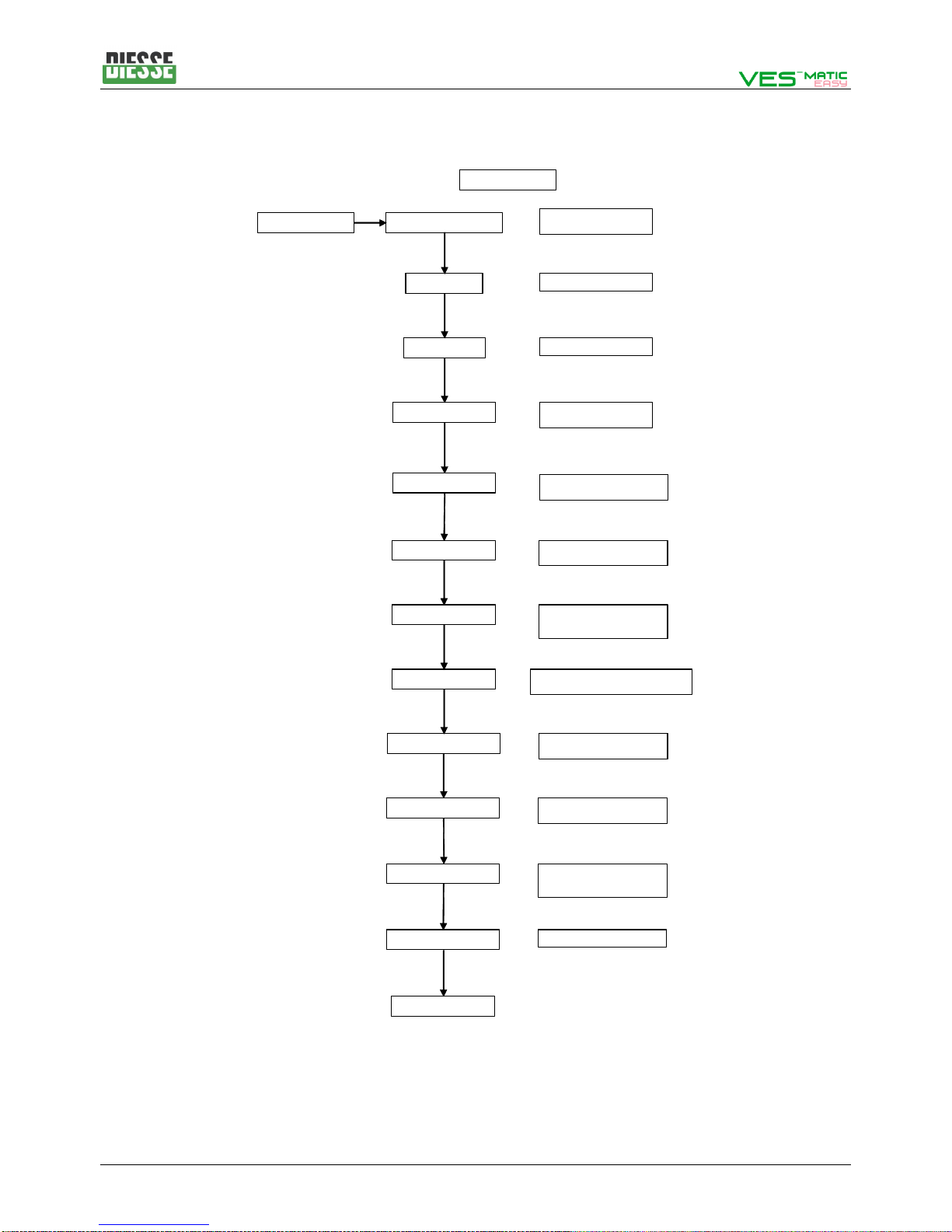
The SERVICE menu supplies a list of useful functions for the various calibration and testing operations
described below:
VES MATIC EASY
READ PHOTOSENSOR
MOTOR TEST
SENSOR TEST
SENSOR CALIB.
SELECT TEST
CHECK STATUS OF HOME
SENSOR & PHOTOCELL
SENSORS TEST
CALIBRATION OF
READING UNIT
MOVIMENT TEST
BAR CODE TEST SERIAL TEST OF
BARCODE READER
PRINT SETTINGS
RETURN TO MAIN
PRINTING OF CALIBRATION VALUES
AND VES EASY SETTINGS
MAX HEIGHT STROKE ADJUSTMENT OF
READING UNIT CARRIAGE
CHANGE ADDRESS CONFIGURATION
OF ID ADDRESS
(HOST CONNECTION)
TIME NORMAL/FAST SETTING OF TIMES ANALYSIS
FOR DEBUGGING
READ ANA COUNTER VIEWING OF
THE ANALYSIS COUNTER
PRINT ERRORS PRINTING OF ERRORS
RECORDED
DURING ANALYSIS CYCLES
CYCLES TEST SETTING OF CYCLES TEST
To exit select RETURN TO MAIN MENU and press OK.
For testing and calibration it is necessary to use the printer, therefore it is recommended to check that
the printer is working and that it contains paper.

Service Manual
[17/76] 11 Rev.1.1 of 15/04/2017
3.1.2. TEST STATUS OF SENSORS & HOME PHOTOCELL
[READ PHOTOSENSOR]
This function allows for performing the first check of the status of the optical sensor (the software sets
the current of the emitters at 20mA by default) and home photocell.
Useful function for the testing of the boards before mounting on the movement/analysis unit and for an
additional check before closing the instrument with side safety panels.
Procedure:
1. Select the item ‘READ PHOTOSENSOR’ with the ▲and ▼ keys from Select test menu and then
press OK.
2. The instrument is set up for carrying out these tests with the carriage of the reading unit in two
different positions:
- with the reading unit in the home position (on standby)
- with the reading unit in mid-stroke (by initially moving the motor).
As soon as this function is selected the software displays the following request:
-Press OK to perform the test of the sensors and Home photocell with the carriage of the reading
unit one third along the maximum stroke.
-Press any key to perform the test in the Home position.
3. The sensors will be displayed in the following format:
Photograph of the status of the optical and mechanical sensors of the instrument.
L= Light-OPEN D= Dark-CLOSED
4. By performing simple manual operations, like inserting and extracting a test tube from one of the 10
positions in the test tube tray or blacking out the Home photocell, it is possible to check the
functioning.
Press any key to return to the previous menu.
3.1.3. MOTOR TEST
This function allows for performing the first test for checking the motor movement; more specifically, it
checks that the complete stroke has been carried out in the scheduled time (and preferably without
losing the motor pitch*) as well as checking that the home photocell functions correctly (in the case of
errors the message ERROR READING will appear on the display or the number of STEPS LOST during
the movement will be printed).
Procedure:
1. Select the item ‘MOTOR TEST’ from Select test and press OK.
2. The number of motor steps to be performed is requested:
LLLLL LLLLL L
CYCLE NUMBER 1
MOTOR (YES = OK)

Service Manual
Rev.1.1 of 15/04/2017 12 [18/76]
To set the number of cycles (max 20 cycles) :
- Use the ▲/▼ keys to change value of the units.
- Use the Line Feed key to increase by 10 the value to be set.
3. To confirm the value entered and start the cycle press OK.
The instrument allows a 30-second pause between each cycle.
*It is foreseen that the instrument may lose several steps during the movement without
however any affect on the quality of the readings. The motor strokes are to be considered
as valid as long as the loss of the steps is < a 16 (corresponding to 0.5mm) (see Printing
Report).
3.1.4. SENSOR TEST
[SENSOR TEST]
This function allows for checking the motor steps by measuring the height of the test tubes.
Procedure:
1. Select the item ‘SENSOR TEST’ from the Select test menu
2. Introduce 10 cuvettes containing the test strips into the test tube trays and press OK.
3. The instrument will perform a full stroke and displays the following message:
Where Y = YES position occupied, value valid. N = Non present.
Press OK to return to the previous menu.
3.1.5. SENSOR CALIBRATION
To perform the calibration (fine tuning) of the sensors it is necessary to use 10 test tubes containing 3ml
calibration latex [LOW] and 10 test tubes containing the 2ml calibration latex [HIGH]
The instrument foresees two calibration modes, either for single sensors or simultaneously for all 10
optoelectronic units.
Procedure for calibrating the10 optoelectronic units:
-Select the item ‘SENSOR CALIB.’ from the Select test menu and press OK
-At the request ‘ALL=OK SINGLE=UP’ press OK to start the simultaneous calibration procedure.
-The instrument will take the reading carriage to mid-stroke and request the inserting of the test
tubes with the 3ml calibration latex [LOW] ‘INSERT LOW’
-Press OK once the test tubes have been inserted on LOW.
-The instrument will carry out a series of reading until, on lowering the current to the emitter sensor,
it manages not to perforate the 3ml latex.
-At this stage the instrument will request the insertion of the test tubes containing the 2ml calibration
latex [HIGH], ‘INSERT HIGH’, insert the test tubes and press OK.
YYYYY YYYYY

Service Manual
[19/76] 13 Rev.1.1 of 15/04/2017
-The instrument will carry out a series of readings until, via the adjustment of the emitter sensor
current, it manages not to perforate the 2ml latex.
-The instrument calculates the mean value between the two readings of each group and memorises
it in the EEPROM as well as printing a report.
Procedure for calibrating one single sensor:
-Select the item ‘SENSOR CALIB.’ from the Select test menu and press OK
-At the request ‘ALL=OK SINGLE=UP’ press ▲to start the procedure for calibrating one single.
-The position of the sensor to be calibrated will appear on the display:
-Use the ▲/▼ keys to select the position to be calibrated if different from the one displayed and
press OK to start up the calibration procedure.
-The instrument will take the reading carriage to mid-stroke and request the inserting of the test tube
with the calibration latex 3 [LOW] ‘INSERT LOW’.
-Press OK once the test tube has been inserted on LOW.
-The instrument will carry out a series of reading until, on lowering the current to the emitter sensor,
it manages not to perforate the 3ml latex.
-At this stage the instrument will request the insertion of the test tubes containing the 2ml calibration
latex [HIGH], ‘INSERT HIGH’, insert the test tube and press OK.
-The instrument will carry out a series of readings until, via the adjustment of the emitter sensor
current, it manages not to perforate the 2ml latex.
-The instrument calculates the mean value between the two readings of the group calibrated and
memorises it in the EEPROM as well as printing a report.
-The software is set for calibrating the next sensor after the one calibrated.
To exit from the Sensor Calibration menu press Line Feed (at any point of the programme except for
during the calibration).
3.1.6. BARCODE TEST
This function allows for testing the communication and speed of the serial port and the external reader. It
is advised only to connect the barcode reader to the instrument when turned off.
Procedure:
1. Select the item ‘BAR CODE TEST’ from the Select test menu,
2. Press OK: the following request will appear on the display:
3. Take a barcode and check that the code indicated on the display matches the one on the test tube.
Press OK to return to the previous menu.
SENSOR 1
INSERT BARCODE

Service Manual
Rev.1.1 of 15/04/2017 14 [20/76]
3.1.7. ADJUSTING THE CARRIAGE STROKE READING
[MAX HEIGHT]
Adjustment necessary in the event of the following problem occurring: during the movement the read
sensor carriage completes the upwards stroke and tries to go further than the maximum height, resulting
in a loss of steps (Error printout) or fails to correctly complete the stroke up to the maximum height.
Procedure:
1. Select the item ‘MAX HEIGHT’ from the Select test menu,
2. Press OK, the max. height set in mm will be displayed.
3. Use the keys ▲/▼ to change the value (from 64mm min. to 72mm max.) with 0.1mm steps.
4. Use the Line Feed key to increase or decrease by 0.5mm at a time.
5. Press OK to save the value entered and return to the previous menu.
NB: The default value is 67.0 mm
3.1.8. CONFIGURATION OF ID No.
[CHANGE ADDRESS]
This menu allows for setting the ID number of the instrument to allow for identifying it during connection
to the mains (Transmission Speed : 19200 bit/s; data format: 8 data bits, 1 stop bit and no parity bit).
Procedure:
1.Select the item ‘CHANGE ADDRESS’ from the Select test menu.
2.Press OK, and the address entered will appear on the display.
3.Use the keys ▲/▼ to change the value of the units (hexadecimal, from 0 to F).
4.Use the Line Feed line to increase the value to be set by 10 hexadecimals.
5.Press OK to save the value entered and return to the previous menu.
The programming software is pre-arranged to communicate with the instruments with and ID
number of ‘00’.
Therefore, before beginning to update the instrument it is advisable to carry out a check and
if necessary set the ID number to 00. At the end of the programming restore the ID used.
3.1.9. PRINT SETTINGS
At the end of the calibrating, this function allows for obtaining a printout that summarises the settings of
the instrument (including the calibration values of the sensors).
More specifically, it contains:
-the SW version installed
-the ID address and speed of the serial ports (USB and Barcode)
-date and time set
ADDRESS 0X00
Other manuals for VES-MATIC EASY
1
Table of contents
Other Diesse Measuring Instrument manuals


Popular Measuring Instrument manuals by other brands


Extech Instruments
Extech Instruments EX850 user manual

HT
HT I-V400w-SOLAR I-Vw user manual

PCB Piezotronics
PCB Piezotronics IMI SENSORS EX608A11 Installation and operating manual

Sanwa
Sanwa PDR302 instruction manual

CARLO GAVAZZI
CARLO GAVAZZI UDM 35 - PROGRAMMING instruction manual

Keysight
Keysight N9010B EXA Installation note