2.
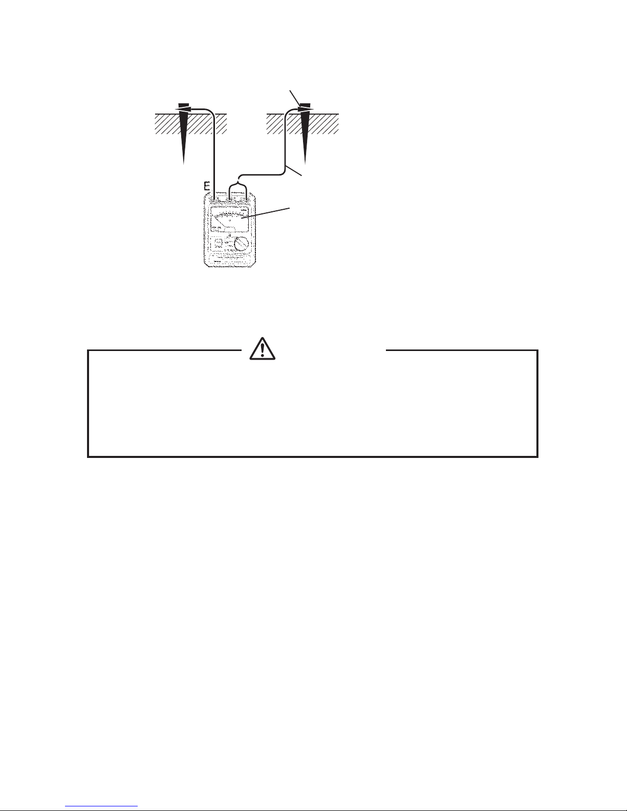
Measurement of Earth Resistance Using the Tripolar System
CAUTION:
Make sure the earth bars are inserted into the ground securely. If they are
improperly inserted, R
P
(R
S
) and R
C
(R
H
) values increase. This will result in
errors in measurement values and instabilities in indicated values.
1. The range switch is placed at one of the three ranges to be selected
according to the size of the earth resistance (R
E
).
2. Press the MEASURE PUSH switch. The power indicator lamp (ON) will
light red and the pointer will point at the earth resistance value (R
E
).
3. For the “X1” range, the figures along the arc are read directly (0〜10
Ω). For the “X10” and “X100” ranges, they are read multiplied by 10 for
0〜100 Ω and by 100 for 0〜1000 Ω.
4. If the red LED (OVER AUX. R) on the upper left of the meter scale
lights after the MEASURE PUSH switch is pressed, this means the
auxiliary grounding resistance value is excessive and correct
measurement cannot be performed. Should this happen, re-insert the
earth bars into the ground.
5. If the power indicatorlamp (ON) starts blinking after the MEASURE
PUSH switch is pressed, this means the batteries are low. Replace
them with new ones. For details, refer to “5. Replacing the Batteries.”
3.
Measurement of Earth Resistance Using the Bipolar System
1. Whenearth is available whose resistance value has beenalready
detected or whose resistance is extremely low and can be regarded
as immaterial with respect to the earth resistance in question, you can
measure unknown earth resistance by taking advantage of the
electrical circuit ground at hand.
2. The earth of unknown resistance is connected to the terminal E.
Next, insert the plugs of the C-terminal connection cord to the P
(S)
and
C
(H)
terminals and connect the alligator clip to a point with known earth
resistance value.
3. The value measured with this method is the sum of an unknown
earth resistance R
X
and known earth resistance rE. If the value is
already known, obtain the true value by subtracting the known earth
resistance value rE from the meter reading RE.
Make sure that the object being measured — an electric appliance, for
example — is properly grounded. If the object is improperly grounded or
not grounded, commercial voltage may leak into or be applied to the
object. Double-check all safety precautions before starting measurement.
WARNING
−
19
−