Diesse Chorus Trio User manual

SERVICE MANUAL
FOR CHORUS TRIO (REF. 81200) AND CHORUS TRIO RAS (REF. 81220)
REVISION 1 Issued in April 2021
Software version 7.xx
THIS MANUAL IS TO BE USED FOR CHORUS TRIO INSTRUMENTS STARTING
FROM S/N 4000 OR UPDATED WITH CHORUS EXPANDER UPGRADE KIT
(REF 83600)
FOR IN VITRO DIAGNOSTIC USE ONLY

This page is intentionally left blank

Rev. 1.0 (04-2021)
CHORUS TRIO EXPANDER | SERVICE MANUAL
1
CHORUS TRIO models:
The present manual refers to the following CHORUS TRIO models with the 7.xx family
of software installed:
Catalog number
Description
81200
CHORUS TRIO
81220
CHORUS TRIO RAS
Manual revisions list:
Manual revision
Description of changes
0 of 03/2021
First issue relative to Chorus TRIO with Expander
1 of 04/2021
Correction of paragraph 2.2 following the replacement of the
internal barcode reader

2
CHORUS TRIO EXPANDER | SERVICE MANUAL
Rev. 1.0 (04-2021)
Manufacturer
DIESSE DIAGNOSTICA SENESE SpA
Strada dei Laghi 39, 53035 Monteriggioni (SI) Italy
Tel. +39 0577 307109, Fax. + 39 0577 307106
www.diesse.it
TECHNICAL SUPPORT
Strada dei Laghi 39, 53035 Monteriggioni (SI) Italy
Tel. +39 0577 307109, Fax. + 39 0577 307106
Numero Verde: 800 606932
e-mail: technicalsupport@diesse.it
No page in this manual may be reproduced in any form or by any means, electronic,
mechanical or otherwise, for any use whatsoever without prior written permission
from DIESSE Diagnostica Senese S.p.A.

Rev. 1.0 (04-2021)
CHORUS TRIO EXPANDER | SERVICE MANUAL
3
Symbols:
Key of graphic symbols
Instrument meeting the requirements of the European Directive
98/79/EC on in vitro diagnostic medical devices (98/79/CE).
In vitro
diagnostic medical device
Manufacturing date
Serial number
Manufacturer
Key of electric and safety symbols
Protective conductor
WEEE: Waste electrical and electronic equipment –Separate
Collection is required pursuant to Legislative Decree No. 49 of
March 14. 2014 (Italy), on “implementation of Directive 2012/19/EC.”
Attention: please read this manual carefully and comply with the
safety symbols.
Caution: risk of electrical shock
Caution: laser beam
BIOHAZARD: potential risk of contamination handling infectious
substances
Crush hazard: moving parts can crush and cut; keep hands away
Risk of thermal shock due to the warming of the tray for samples
Risk of puncture to hands and fingers due to the presence of
needles for collection and dispensing

4
CHORUS TRIO EXPANDER | SERVICE MANUAL
Rev. 1.0 (04-2021)
LIMITATIONS AND WARNINGS
Version 7.00, revision 0 of this manual corresponds to the CHORUS TRIO model of the
instrument with the 7.xx family of software installed.
It was drafted and carefully reviewed and this version is closely related to the
instrument model
(data can be obtained from the instrument’s ID plate)
and the
version of the software that controls it
(data can be obtained through a procedure on
the instrument itself)
.
It must be read carefully before using the instrument, especially the parts relating to
safety.
ATTENTION
Do not use this manual except in its complete form.
If this manual is used in an incomplete form, DIESSE Diagnostica Senese S.p.A.
declines any responsibility for adverse results.
ATTENTION
Any instrument updating done with the customer’s authorization requires that the
user manual be updated in a corresponding manner.
DIESSE Diagnostica Senese SpA accepts no responsibility for damage caused
directly or indirectly by errors, defects, or incidents due to any use of this manual that
does not correspond with the version of the supplied instrument.

Rev. 1.0 (04-2021)
CHORUS TRIO EXPANDER | SERVICE MANUAL
5
Index:
SOMMARIO
1MOVING THE STRIPS................................................................................................................................................................... 9
1.1 THE WORKSTATIONS............................................................................................................................................................. 9
1.2 THE TRAY.......................................................................................................................................................................................10
1.3 TRAY ROTATION .......................................................................................................................................................................10
1.3.1 ABSOLUTE SENSOR .............................................................................................................................................................12
1.3.2 STEP CHECK................................................................................................................................................................................12
1.3.3 SYNCHRONIZATION.............................................................................................................................................................13
1.4 STRIP HOUSING........................................................................................................................................................................14
1.5 TRAY LOCK...................................................................................................................................................................................15
1.6 CALIBRATIONS AND CONTROL PARAMETERS..................................................................................................15
1.6.1 ALIGNMENT AND CENTERING OF THE PLATE..............................................................................................15
2Strip recognition unit..................................................................................................................................................................17
2.1 Strip presence sensor (SPS)...............................................................................................................................................17
2.1.1 Check SPS sensor (Strip Presence Sensor).........................................................................................................17
2.2 Internal barcode reader.......................................................................................................................................................18
2.2.1 Internal barcode reader check and calibration ............................................................................................. 18
3Transfer unit.....................................................................................................................................................................................20
3.1 Dispensing hydraulic circuit............................................................................................................................................20
3.2 The strip, needles and the well........................................................................................................................................21
3.3 Dispenser.......................................................................................................................................................................................21
3.4 X-axis movement....................................................................................................................................................................23
3.5 The syringe unit........................................................................................................................................................................24
3.6 The transfer function ............................................................................................................................................................25
3.6.1 Transfer function parameters......................................................................................................................................25
3.6.2 The double dispensing needle....................................................................................................................................25
3.6.3 Priming of the dispensing and wash circuit................................................................................................... 26
3.6.4 Withdrawal................................................................................................................................................................................. 26
3.6.5 Drying of the tip...................................................................................................................................................................... 28
3.6.6 Perforation of the cuvette membrane ................................................................................................................ 28
3.6.7 Level detection........................................................................................................................................................................ 29
3.6.8 Mixing............................................................................................................................................................................................. 30
3.6.9 Simple transfer..........................................................................................................................................................................31
3.7 CALIBRATIONS AND CONTROL PARAMETERS.................................................................................................33
3.7.1 Circuit transfer..........................................................................................................................................................................33
3.7.2 Dispensers ...................................................................................................................................................................................33
3.7.3 X-axis movement .................................................................................................................................................................. 34
3.7.4 Level sensor test......................................................................................................................................................................35
3.7.5 Transfer test................................................................................................................................................................................35
3.7.6 Strip perforation......................................................................................................................................................................37
4Optical unit .......................................................................................................................................................................................38
4.1 Light source................................................................................................................................................................................38

6
CHORUS TRIO EXPANDER | SERVICE MANUAL
Rev. 1.0 (04-2021)
4.2 The optical device...................................................................................................................................................................38
4.3 The optical channel ...............................................................................................................................................................39
4.4 Positioning of filters.............................................................................................................................................................. 40
4.5 Optical calibration .................................................................................................................................................................40
4.5.1 Transmittance and absorbance................................................................................................................................40
4.5.2 Alignment of the optical fibres................................................................................................................................... 42
4.5.3 Calibration of the optical channels.........................................................................................................................44
4.5.4 Calibration of the dark electronic offset..............................................................................................................44
4.5.5 Calibration of light emission.........................................................................................................................................44
4.5.6 The control ramp................................................................................................................................................................... 45
4.5.7 Report of the virtual ramp..............................................................................................................................................46
4.5.8 Control window......................................................................................................................................................................48
4.6 Optical unit testing procedure ..................................................................................................................................... 49
4.6.1 Setting of the optical filter offset...............................................................................................................................49
4.6.2 Calibrating the offset (dark reading).....................................................................................................................49
4.6.3 Calibrating the light............................................................................................................................................................49
4.6.4 Check of absorbance at 650 nm with control solutions.................................................................. 50
4.6.5 check of absorbance at 450 nm with control solutions...........................................................................51
5WASHING unit................................................................................................................................................................................53
5.1 Hydraulic wash circuit..........................................................................................................................................................53
5.2 Tank probes ................................................................................................................................................................................54
5.3 The washer ..................................................................................................................................................................................55
5.4 The drying station...................................................................................................................................................................56
5.5 Collection wells.........................................................................................................................................................................56
5.6 Washing procedure ..............................................................................................................................................................58
5.7 Washing circuit testing procedure.............................................................................................................................59
5.7.1 Supplying of buffer from washer #1....................................................................................................................... 59
5.7.2 Supplying of buffer from washer #2...................................................................................................................... 59
5.7.3 Washing of the piping for washer #1..................................................................................................................... 59
5.7.4 Washing of the piping for washer #2 ................................................................................................................... 59
5.7.5 Aspiration at drying station #3...................................................................................................................................60
5.8 CONTROL PARAMETERS.................................................................................................................................................. 60
5.8.1 Filling level of washer #1 (step 21) .............................................................................................................................60
5.8.2 Filling level of washer #2 (step 25)...........................................................................................................................60
6The drain circuit.............................................................................................................................................................................62
6.1 The main waste well..............................................................................................................................................................62
6.1.1 Normal operation.................................................................................................................................................................. 63
6.1.2 Obstructed drain...................................................................................................................................................................64
6.1.3 Full waste tank........................................................................................................................................................................64
6.1.4 Faulty drain pump................................................................................................................................................................ 65
6.2 Waste circuit testing procedure...................................................................................................................................65
6.2.1 Checking of waste level warning sensor (WS)............................................................................................... 65
6.2.2 Checking of waste level error sensor (ES).......................................................................................................... 66

Rev. 1.0 (04-2021)
CHORUS TRIO EXPANDER | SERVICE MANUAL
7
7Temperature control..................................................................................................................................................................67
7.1 Temperature control of the instrument..................................................................................................................67
7.2 Measuring chamber..............................................................................................................................................................67
7.3 Heater ............................................................................................................................................................................................ 68
7.3.1 Electrical properties of the heater...........................................................................................................................68
7.4 Cycle temperature .................................................................................................................................................................69
7.5 Stand-by temperature.........................................................................................................................................................69
7.6 Procedure for testing the temperature control system...............................................................................69
7.6.1 Checking of the instrument temperature sensor...................................................................................... 69
7.6.2 Chamber temperature control.................................................................................................................................. 69
7.6.3 Strip temperature correction ...................................................................................................................................... 69
8Speaker-printer display.............................................................................................................................................................71
8.1 Display .............................................................................................................................................................................................71
8.2 The speaker..................................................................................................................................................................................71
8.3 The printer ....................................................................................................................................................................................71
8.3.1 Printer testing...........................................................................................................................................................................72
9Electronic Parts..............................................................................................................................................................................73
9.1 General Map...............................................................................................................................................................................73
9.2 Carrier+IMX8 Board ...............................................................................................................................................................75
9.2.1 Power supply and connections..................................................................................................................................75
9.3 CPU 2010 Board and Driver 2010 Board...................................................................................................................76
9.3.1 Power supply............................................................................................................................................................................ 77
9.3.2 Description of the Test Points and CPU 2010 board jumpers...........................................................86
9.3.3 DESCRIPTION OF THE TEST POINTS AND THE DRIVER 2010 BOARD JUMPERS ...........87
9.3.4 Troubleshooting.....................................................................................................................................................................87
9.4 Low Power...................................................................................................................................................................................87
9.4.1 Description................................................................................................................................................................................. 87
9.4.2 Power supply and connections.................................................................................................................................87
9.4.3 Troubleshooting.....................................................................................................................................................................94
9.5 Power Supply............................................................................................................................................................................ 94
9.6 DESCRIPTION............................................................................................................................................................................95
9.6.1 Troubleshooting...................................................................................................................................................................100
9.7 Connectors board................................................................................................................................................................ 100
9.7.1 Description...............................................................................................................................................................................100
9.7.2 Troubleshooting................................................................................................................................................................... 103
10 Service Procedures................................................................................................................................................................... 104
10.1 Programming firmware CPU 2010........................................................................................................................... 104
10.1.1 Service application.............................................................................................................................................................104
10.1.2 Successful connection with CPU 2010 board.........................................................................................104
10.1.3 Unsuccessful Connection with CPU 2010 board.................................................................................. 105
10.1.4 Firmware upload on the CPU 2010 board.................................................................................................106
10.1.5 Replacement of the Carrier+IMX8 board...................................................................................................108
10.1.6 Methods saving...............................................................................................................................................................108
10.1.7 Calibrations saving....................................................................................................................................................... 109

8
CHORUS TRIO EXPANDER | SERVICE MANUAL
Rev. 1.0 (04-2021)
10.1.8 Software upgrade on the Carrier+IMX8 board...................................................................................... 109
10.1.9 Methods and Calibrations upload on the Carrier+IMX8 board ...................................................111
10.2 Programming BarCode reader Zebex Z 3080................................................................................................... 112
10.2.1 Connect the reader to the instrument through the RS232 cable............................................112
10.2.2 Disconnect the RS232 cable...................................................................................................................................112
10.2.3 PROGRAMMING PARAMETERS..........................................................................................................................113
10.3 Maintenance.............................................................................................................................................................................118
10.3.1 Routine maintenance..................................................................................................................................................118
10.3.2 Periodic maintenance.................................................................................................................................................118
10.3.3 Wash well for the dispenser needles...............................................................................................................119
10.3.4 Dispensers #1 and #2....................................................................................................................................................121
10.3.5 X-axis guide..........................................................................................................................................................................121
10.3.6 Washers 21 –25 –28......................................................................................................................................................122
10.3.7 Optical unit..........................................................................................................................................................................123
10.3.8 Washer wells......................................................................................................................................................................125
10.3.9 Upper plate..........................................................................................................................................................................126
10.3.10 Carousel .................................................................................................................................................................................126
10.3.11 Peristaltic pumps ...........................................................................................................................................................126
10.3.12 Diaphragm pump .........................................................................................................................................................127
10.3.13 Hydraulic waste and syringe unit......................................................................................................................127
10.3.14 Hydraulic unit....................................................................................................................................................................128
10.3.15 Syringe Unit ........................................................................................................................................................................128
10.3.16 Rotation..................................................................................................................................................................................129
10.3.17 Tray synchronization device ..................................................................................................................................129
10.3.18 Led box and filter handler .......................................................................................................................................129
10.3.19 Tank probes ........................................................................................................................................................................129
10.3.20 Tubing .................................................................................................................................................................................... 130
Rev. 1.0 (04-2021)
CHORUS TRIO EXPANDER | SERVICE MANUAL
9
1MOVING THE STRIPS
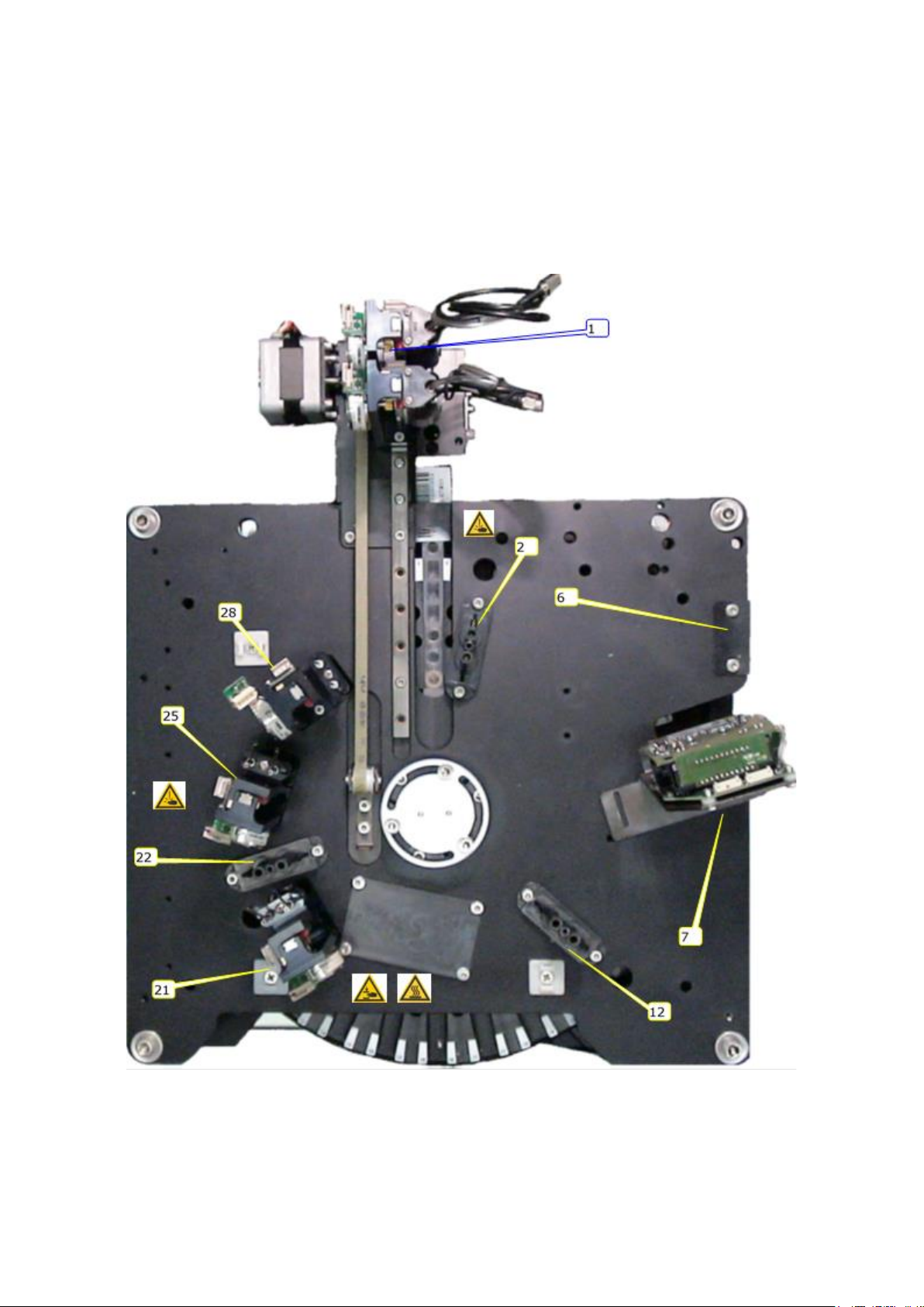
1.1 THE WORKSTATIONS
The functioning of the system is based on the carrying out of hydraulic, optical and
mechanical operations in certain positions called workstations. The workstations are
mounted on a base located above the tray called the upper level, shown in the figure
below:
Fig. 1-1

10
CHORUS TRIO EXPANDER | SERVICE MANUAL
Rev. 1.0 (04-2021)
Pos.
Function
1
fluid transfer station, where liquids are transferred from one well to another. The
positioning unit is able to move from one well to another and to transfer the
liquids.
2
1st reading station
6
station where the presence of the strip is checked
7
station for the reading of the strip’s barcode
12
2nd reading station
22
3rd reading station
21
1st well washer for the strip
25
2nd washer
28
3rd washer (drying)
Since the strip has two reaction cuvettes, wash and reading stations are created so
that the operations can be performed on both cuvettes simultaneously.
1.2 THE TRAY
The device in which the strips are inserted. Composed of a circular plate, mounted on
a pin ending with a pulley at the bottom, is able to rotate between two levels (one
upper and one lower) strengthened by four columns. The support surfaces also
border the upper and lower part of the measuring chamber, which is completed with
the special circular plastic crown fastened around the tray.
The tray is locked in place by tightening the locking ring-nut (see Fig. 1-2).
1.3 TRAY ROTATION
The rotation direction of the tray is determined by a motor whose shaft is joined to a
pulley which drives the rotor by means of a rotational belt.
The motor is mounted on a tensioning bracket so that the belt can be tightened to
one’s liking. Tensioning is done by turning the adjustment screw so that the bracket
moves closer or farther from the tray’s axis. A temporary fastening screw locks the
tensioning bracket in place so that the belt tightness can be checked. Locking the
fastening screws on the bracket holds the motor in position and maintains the belt
tension.
Tray positioning is checked by:
1. absolute positioning sensor (7) which sets the mechanical zero position
2. relative hole sensor (13) that check the movement of the tray (step check)
3. synchronization device abbreviated TSD (6) that allows the tray to be locked in
each of the work positions.
Rev. 1.0 (04-2021)
CHORUS TRIO EXPANDER | SERVICE MANUAL
11
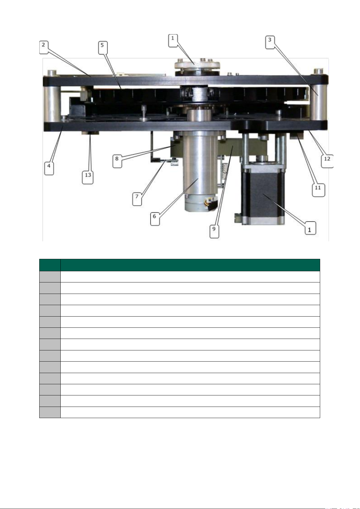
Fig. 1-2
No.
Description
1
Locking ring-nut
2
Upper surface
3
Column
4
Lower surface
5
Strip tray
6
Tray synchronization device (TSD)
7
Absolute tray sensor
8
Tray shaft with pulley
9
Drive belt
10
Drive shaft with pulley
11
Temporary lock nut
12
Tensioning bracket
13
Hole sensor (relative)
12
CHORUS TRIO EXPANDER | SERVICE MANUAL
Rev. 1.0 (04-2021)
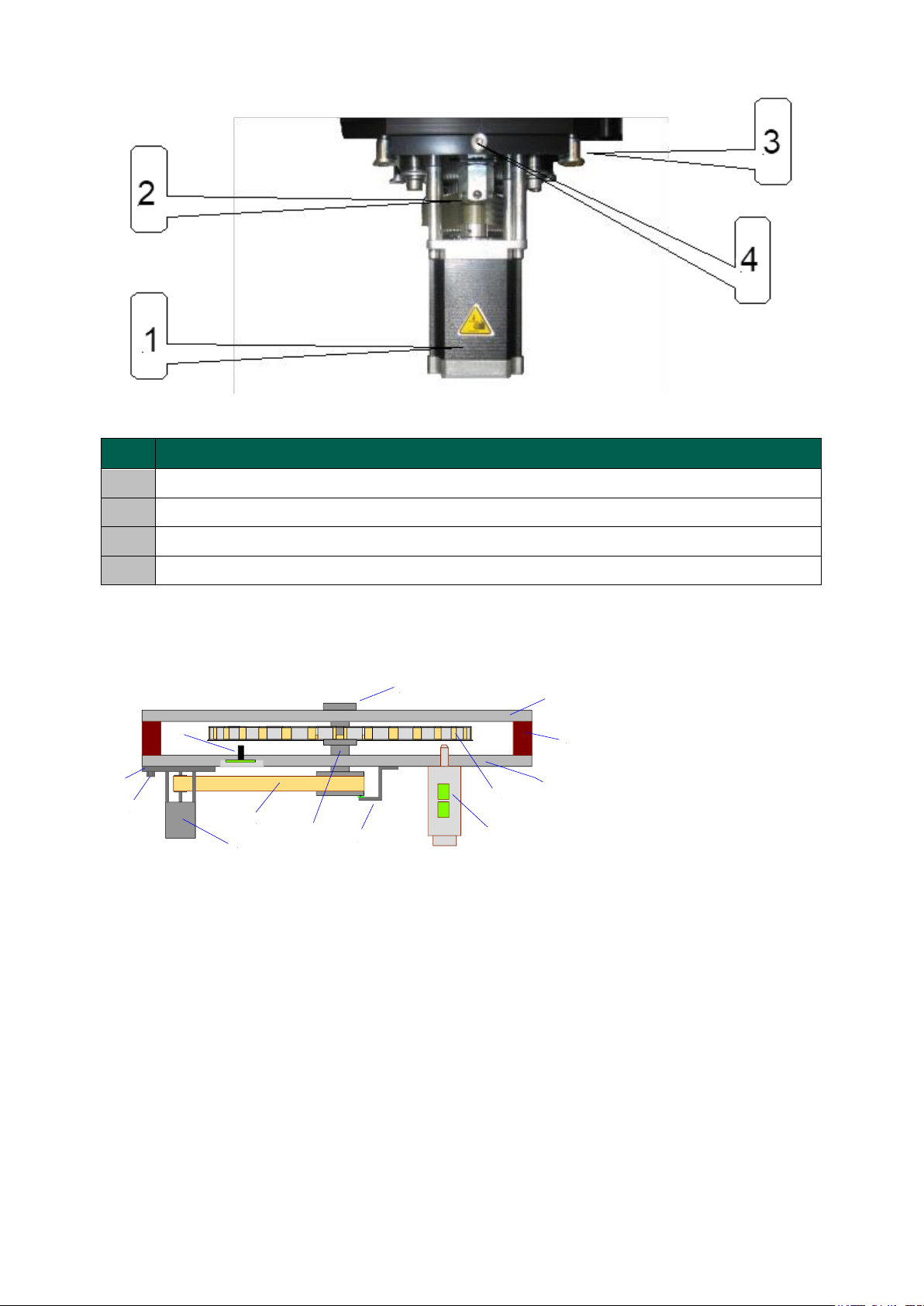
Fig. 1-3
No.
Description
1
Motor
2
Temporary fastening nut
3
Motor unit movement slide
4
Belt tensioning screw
2
7
4
3
5
6
1
8
9
13
11
12
10
1. locking ring-nut
2. upper surface
3. column
4. lower surface
5. strip tray
6. Tray Synchronization
Device (TSD)
7. absolute tray sensor
8. drive shaft with pulley
9. drive belt
10. motor with pulley
11. temporary fastening
nut
12. tensioning bracket
13. hole sensor
14. (relative)
Fig. 1-4
1.3.1 ABSOLUTE SENSOR
A small magnet is mounted on the rotational pulley of the drive shaft which is
detected by a Hall sensor located on a small plate fastened by an angular bracket.
The magnet ensures an absolute mechanical zero position and therefore alignment
of the tray.
1.3.2 STEP CHECK
Every step that the tray makes during the cycle needs to be checked to ensure that
it was done correctly.

Rev. 1.0 (04-2021)
CHORUS TRIO EXPANDER | SERVICE MANUAL
13
The check is done using an infra-red reflection sensor that “detects” the passage
between the plate full area (illuminated sensor) and the area with the hole (dark
sensor).
The rotation control software analyses the time intervals of the passages between the
dark zones and the illuminated zones and checks that the rotor is turning correctly.
Fig. 1-5
1.3.3 SYNCHRONIZATION
Once the rotation is finished, or after the shaking of the plate has ended, the tray is
correctly positioned by a mechanical unit made up of a special device called the Tray
Synchronization Device (TSD) or simply the tray synchronizer, which inserts a cone-
headed cylinder in one of the holes beneath the tray that correspond to each of the
30 strip insertion positions.
The wedge-shaped pin is quickly moved by a motor on which a worm screw is
mounted. Two sensors check the positioning. The first (limit switch) checks the
starting mechanical position (detail A in the Fig. 1-6). The other is used to check the
alignment of the plate before carrying out the complete insertion of the pin (detail B
in the Fig. 1-6). At the end of the operation the pin completely enters the hole and
locks the tray in the desired position. (detail C in the Fig. 1-6).
2
1
1. hole sensor (relative)
2. reference hole

14
CHORUS TRIO EXPANDER | SERVICE MANUAL
Rev. 1.0 (04-2021)
1
A
B
C
3
4
2
1. conical pin of the TSD
2. positioning hole
3. relative position sensor
4. absolute sensor (at rest)
Fig. 1-6
1.4 STRIP HOUSING
The 30 strips housing is made of radial slots situated 12° from each other, which were
specially shaped in order to assure easy insertion and to prevent the strip from
moving during the movement of the plate (rotation and mixing). Above all, the seat
allows the strip to maintain the same positioning under the three optical reading
stations.
The strip is inserted in the slot and is kept in position by the spring located at the end
of the slot, which keeps the strip locked in position by holding the last well.
Upon insertion the strip must be pushed to the bottom of the seat so it can be held
by the spring.
The insertion of the strip into the slot is aided by the bevelling of the lower edge of
the plate.
There are two holes at the bottom of every slot that allow the optical ray to pass
through. The diagram below shows the top view of a plate with 28 strips fully inserted,
one strip partially inserted and one position empty.

Rev. 1.0 (04-2021)
CHORUS TRIO EXPANDER | SERVICE MANUAL
15
1
2
3
5
4
6
7
Fig. 1-7
1.
spring locking sector
2.
spring
3.
holes for optical reading
4.
strip slot
5.
strip
6.
strip slot (front view)
7.
bevel for strip insertion
1.5 TRAY LOCK
When the instrument is switched off, or there is a power outage, the manual or
random rotation of the tray needs to be blocked in order to prevent damage to the
dispenser needles and to the workers. This function is carried out by the Tray Lock
Device (TLD). It is composed of an electro-magnet which is released and
mechanically locks the tray when the power is cut off. Vice versa, when the system is
powered up, the mechanical lock is removed and the tray may be moved by the
control system.
13
2
Fig. 1-8
1.
lock pin
2.
centering hole
3.
solenoid
1.6 CALIBRATIONS AND CONTROL PARAMETERS
1.6.1 ALIGNMENT AND CENTERING OF THE PLATE.
Plate alignment is one of the operations for setting the instrument.
The aligning of the plate is designed to position the plate in the exact work point
where the following conditions have to be checked:

16
CHORUS TRIO EXPANDER | SERVICE MANUAL
Rev. 1.0 (04-2021)
▪Plate position no. 1 must be centered with the dispenser slit; in particular, the
direction of the dispensing needles must be centered with the strip cuvettes.
▪Cuvettes no. 5 and 6 of the strips must be perfectly centered with the two
optical channels of the interleavers.
▪
The plate is aligned when the TSD enters the tray cavity without generating any
visible movement of the tray.
The operations to align the tray must be done using the service program present on
The Chorus Trio equipped with the Expander (IMX8) module.
To access the service program, proceed as follow:
Chorus / Utility / Service
The login Password is “diesse”
The plate alignment is obtained acting on the Tray offset parameter. This parameter
represents the number of steps that the tray must carry out, starting from the
absolute position (which is determined by the absolute sensor Fig. 1.4), to reach the
correct alignment. The following operations can be performed to check the
calibration:
1. Open the Motor window:
Chorus / Utility / Service / Diagnostics / Motors
2. Run the Reset Tray with TSD command.
3. Check that the tray doesn’t move when the TSD enters in the tray cavity.
4. If the TSD drag the tray counterclockwise, decrease the Tray offset parameter
until the desired result is obtained.
If the TSD drag the tray clockwise, increase the Tray offset parameter.
To change the parameter, open the Mechanical Calibration window:
Chorus / Utility / Service / Settings / Parameters / Mechanical Calibration
Double click on the row Tray offset and enter the number of correction steps, then
confirm with OK.

Rev. 1.0 (04-2021)
CHORUS TRIO EXPANDER | SERVICE MANUAL
17
2STRIP RECOGNITION UNIT
2.1 STRIP PRESENCE SENSOR (SPS)
The
Strip Presence Sensor
(SPS) is composed by a light emitter located on the upper
level and a corresponding receiver located on an electronic board, located in a special
housing on the lower level.
If a strip has been inserted into the tray housing, the handle stops the light beam, and
the receiver can detect the presence of the strip. An unlabelled strip cannot be
recognized.
1
A
B
2
1.
light emitter
2.
receiver
Fig. 2-1
2.1.1 Check SPS sensor (Strip Presence Sensor)
1. Insert a labelled strip in position no. 26 of the plate
2. Open the
Motors
window:
Chorus / Utility / Service / Diagnostics / Motors
3. Select the
Tray
item and press the
Reset
command.
4. Open the
Sensors
window:
Chorus / Utility / Service / Diagnostics / Sensors
5. Check at the row
Strip not present
that the sensor is off (grey colour)
6. Come back to the Motor window and select again the
Tray
item, then press
Power Off
7. Move manually the plate of one position and come back to the
Sensors
window
8. Check at the row
Strip not present
that the sensor is on (yellow colour)

18
CHORUS TRIO EXPANDER | SERVICE MANUAL
Rev. 1.0 (04-2021)
2.2 INTERNAL BARCODE READER
The internal barcode reader is an Opticon model MDC-220A linear CCD auto-scan
reader. Specifically, the barcode reading takes place under station n° 7, as
represented below:
1
2
3
4
5
1.
barcode reader
2.
reader bracket
3.
barcode reading beam
4.
tray upper surface
5.
strip being read
Fig. 2-2
Figure 2-3 shows the connections diagram of the internal barcode reader (front view).
CAB533 connects directly with the 2010 CPU while the LD2 LED represents the power
supply LED.
Fig. 2-3
2.2.1 Internal barcode reader check and calibration
1. Insert a strip with a valid code in the position n° 25 of the tray
2. Open the
Motors
window:
Other manuals for Chorus Trio
1
This manual suits for next models
3
Table of contents
Other Diesse Measuring Instrument manuals


