Diggity Designs XLR8 V1 User manual


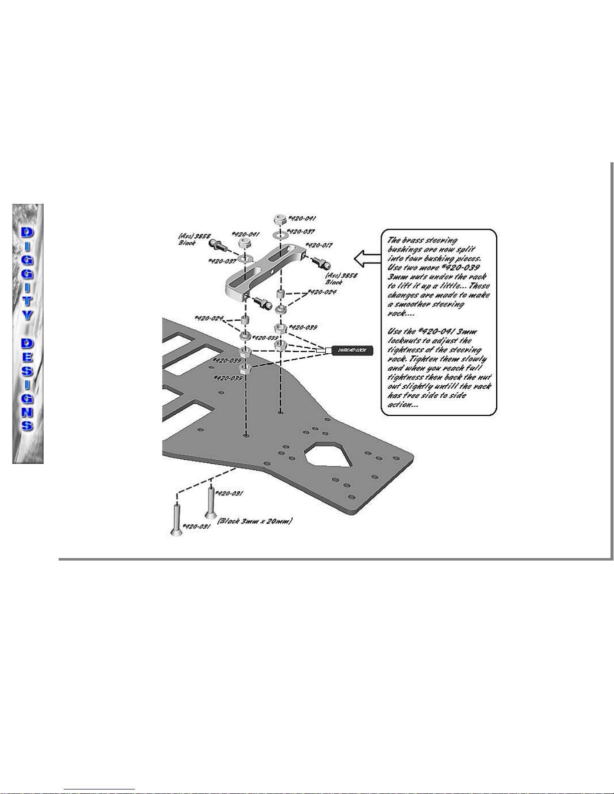
STEP 1 1) Assemble the steering rack (#420-017) using tw 3mm x 20mm flat head stainless screws (#420-031), tw 3mm nuts (#420-039), tw
steering bushings (#420-024), tw 3mm washers (#420-037), and tw 3mm l ck nuts (#420-041). Y u will want t tighten the l ck nuts all the
way. Use the existing black ball ends fr m y ur TC3 r TC4 (#3858) and attach t the steering rack. NOTE: If the rack is binding make sure
the tw 3mm x 20mm flat head screws are n t ff center; y u can use Ass c (#3911) black shims t take any up and d wn play ut.
2) Assemble the fr nt differential h usings (#420-013) as sh wn. Y u will want t start with ne st ck Ass ciated diff shim (#3911) and ne
Diggity Designs diff shim (#420-036) n b th sides f the differential. Y u will make the pr per adjustments later if needed. Using f ur 4-40
x 1/4 flat head stainless screws (#420-427) secure the left and right side differential h usings. DO NOT FULLY TIGHTEN
STEP 1
UPDATE!!
Steering rack update! S me pe ple have had binding pr blems with their steering guide bushings. T take care f this pr blem the ne piece
brass steering guide bushings #420-024 are n w split in t tw parts making f ur brass steering guide bushings. This all ws f r the steering
guide bushings t m ve against each ther m re freely (if binding ccurs, use a little il r lube f r the first run t break the bushings in). We
n w use f ur #420-039 3mm hex nuts under the steering rack, this will raise y ur steering rack and get rid f bump steer.

STEP 2 1) Assemble the rear differential h usings (#420-013) as sh wn. Y u will want t start with ne st ck Ass ciated diff shim (#3911) and ne
Diggity Designs diff shim (#420-036) n b th sides f the differential. Y u will make the pr per adjustments later if needed. Using f ur 4-40 x
1/4 flat head stainless screws (#420-427) secure the left and right side differential h usings. DO NOT FULLY TIGHTEN .
2) Attach the m t r m unt (#420-010) t the chassis using tw 4-40 x 1/4 flat head stainless screws (#420-427) DO NOT FULLY TIGHTEN.
Attach the aluminum antenna m unt (#420-50) t the chassis using ne 4-40 x 1/4 flat head stainless screw (#420-427). There are f ur
m unting h les f r the antenna m unt depending n radi equipment l cati n.

STEP 3 1) Attach the fr nt inner pin bl cks (#420-019) using f ur 4-40 x 1/4 flat head stainless screws (#420-427) t secure them t the chassis DO
NOT FULLY TIGHTEN. NOTE: Y u will use tw 3mm x 8mm flat head stainless screws (#420-030) t attach the serv m unts.
2) Slide the st ck Ass ciated hinge pins (#3866) thr ugh the aluminum fr nt arms (#420-011). Y u will use ne brass swivel bushing(#420-
026) and ne brass washer (#420-062) n each end f the hinge pin as sh wn. Make sure the brass swivel bushings (#420-026) are n c rrectly
sh wn in the b x bel w NOTE: y u might need t press the bushings n using a light hammer. Slide the fr nt arms (#420-011) int the inner
hinge pin bl cks (#420-019) first and then finish the assembly by sliding the 0 degree pin bl ck (#420-020) nt the ther end f the hinge pins
and secure t the chassis using tw 4-40 x 1/4 flat head stainless screws (#420-427). DO NOT FULLY TIGHTEN
Brass Hinge Pin spacer washers! There will either be 8 thin brass spacer washers r 4 (white r black) delrin washers included in y ur kit. If
binding ccurs when using the delrin washers y u will need t sand them with sandpaper t thin them slightly, this will make sure the arms are
free fr m binding.
Delrin C ne Bushings! These are included f r quick replacements f the brass c ne bushings.
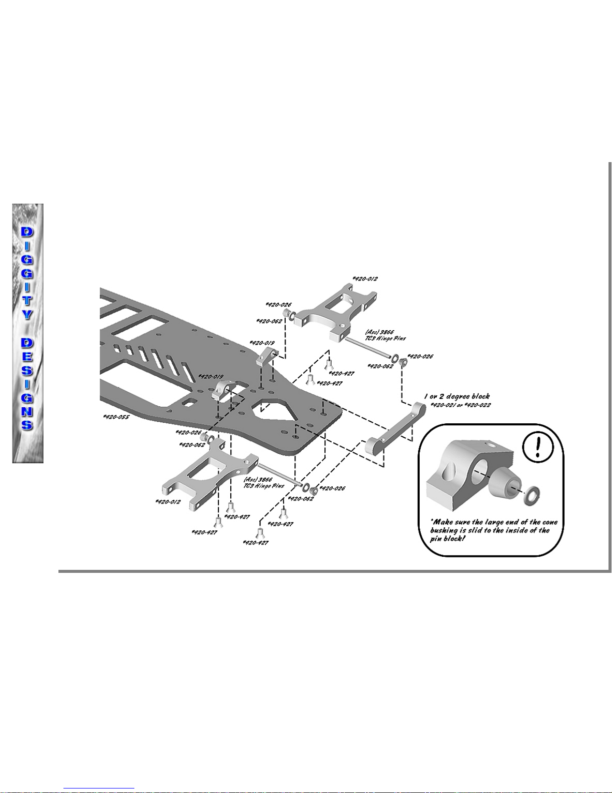
STEP 4 1) Attach the rear inner pin bl cks (#420-019) using f ur 4-40 x 1/4 flat head stainless screws (#420-427) t secure them t the chassis DO
NOT FULLY TIGHTEN.
2) Slide the st ck Ass ciated hinge pins (#3866) thr ugh the aluminum rear arms (#420-012). Y u will use ne brass swivel bushing (#420-
026) and ne brass washer (#420-062) n each end f the hinge pin as sh wn. Make sure the brass swivel bushings (#420-026) are n c rrectly
sh wn in the b x bel w NOTE: y u might need t press the bushings n using a light hammer. Slide the rear arms (#420-012) int the inner
hinge pin bl cks (#420-019) first and then finish the assembly by sliding the 1 r 2 degree pin bl ck (#420-021 r #420-022) nt the ther end
f the hinge pins and secure t the chassis using tw 4-40 x 1/4 flat head stainless screws (#420-427). DO NOT FULLY TIGHTEN

STEP 4
UPDATE!
OPTIONAL! Rear arms Reverse m unting! In the m st recent runnings f the XLR8 kits, racers running ind r n carpet prefer t run the
arms in reverse with the sh cks n the inside f the arms. This all ws f r faster transiti ning thr ugh tight and quick c rners. Make sure t
use a spacer n the t p sh ck m unting screw t slide the sh ck ut m re t level. (It will n t be level, it will angle back at the t p).
TC4 Fr nt Steering Bl cks and rear carriers: We have als n ticed in the m st recent runnings f the XLR8 that the TC4 fr nt steering bl cks
have an extra h le f r the steering ackermann and this new m unting l cati n w rks very well f r the XLR8. When running the rear arms in
reverse we like t use the TC4 rear hub carriers but y u will need t drill a h le f r a set screw like the TC3 nes. We als rec mmend trying
L si fr nt C-hubs and rear hub carriers. Aluminum C-hubs and steering bl cks give y u the m st s lid platf rm.

STEP 5 1) Slide the aluminum fr nt/rear shaft supp rt (#420-014) nt the drive shaft (#420-016) f ll wed by ne Ass ciated 3/16 x 3/8 bearing
(#6906), tw Ass ciated shims (#3911) n te: the tw shims are a starting p int and y u can adjust later if needed by taking away r adding
shims. Slide the Ass ciated pin (#3919) thr ugh the shaft h le. Finish sliding the Ass ciated drive pini n (#3914) nt the drive shaft and
secure with ne 4-40 x 3/16 butt n head stainless screw (#420-430). Use LIGHT thread l ck.
2) Attach the 3mm carb n fibre t p plate (#420-050) t the aluminum fr nt/rear shaft supp rt (#420-014) using tw 4-40 x 1/4 flat head
stainless screws (#420-427). NOTE: y u will have t finish the assembly f the drive shaft in Step 6 bef re y u can secure the t p plate t the
drive shaft unit! DO NOT TIGHTEN TILL LATER

STEP 6 1) Slide the aluminum middle shaft supp rt (#420-015) nt the drive shaft (#420-016) f ll wed by ne Ass ciated 3/16 x 3/8 bearing (#6906).
Slide the gear adapter (#420-018) and spur gear unit nt the drive shaft past the sec nd small h le, slide the sh rt Diggity Designs pin (#420-
061) thr ugh the drive shaft h le and push the gear adapter up t the pin and clip using the Ass ciated Large E clip (#3919). Slide the
aluminum fr nt/rear shaft supp rt (#420-014) nt the drive shaft (#420-016) f ll wed by ne Ass ciated 3/16 x 3/8 bearing (#6906), tw
Ass ciated shims (#3911) n te: the tw shims are a starting p int and y u can adjust later if needed by taking away r adding shims. Slide the
Ass ciated pin (#3919) thr ugh the first shaft h le. Finish sliding the Ass ciated drive pini n (#3914) nt the drive shaft and secure with ne
4-40 x 3/16 butt n head stainless screw (#420-430). Use LIGHT thread l ck.
2) Attach the 3mm carb n fibre t p plate (#420-050) t the aluminum fr nt/rear shaft supp rt (#420-014) using tw 4-40 x 1/4 flat head
stainless screw (#420-427) and t the aluminum middle shaft supp rt (#420-015) using ne 4-40 x 1/4 flat head stainless screw (#420-427).
DO NOT TIGHTEN TILL LATER

STEP 7 1) Attach the drive shaft assembly t the fr nt/rear right and left differential h usings (#420-013) by sliding tw 4-40 x 3/8 flat head stainless
screws (#420-028) thr ugh tw aluminum c untersunk washers (#420-032) and thr ugh the t p plate (#420-050) n each end. Slide ne 4/40 x
1/4 butt n head stainless screw (#420-431) thr ugh the t p plate and secure t the m t r m unt (#420-010). DO NOT FULLY TIGHTEN
2) Attach the drive shaft assembly t the chassis (#420-055) by using six 4-40 x 1/4 flat head stainless screws (#420-427) and securing them t
the aluminum fr nt/rear shaft supp rts (#420-014) and t the aluminum middle shaft supp rt (#420-015). MAKE SURE YOUR DRIVE LINE
DOES NOT BIND AT THIS TIME, IF IT IS TOO LOOSE THEN ADD A SHIM OR TWO WHERE NEEDED AND IF IT IS TOO TIGHT
THEN TAKE A SHIM OR TWO AWAY WHERE NEEDED AND THEN REPEAT STEP 7. M st shim adjustments will be in the differential
h usings, y u will want t shim it s that the drive pini n and diff gears are n t t l se because y u will strip the gears if its n t pr perly
adjusted. Once y u have a set shimming selecti n then y u will always use the same when rebuilding y ur car.

STEP 8 1) Slide ne Ass ciated 4-40 x 3/4 pan head screw (#7413) thr ugh the fr nt sh ck t wer (#420-053) and secure with an Ass ciated 4-40 mini
nut (#7260). Slide ne Ass ciated l ng black ball end (#3858) thr ugh the fr nt sh ck t wer and secure with an Ass ciated 4-40 mini l ck nut
(#4449). Attach the fr nt sh ck t wer (#420-053) using f ur 4-40 x 1/4 flat head stainless screws (#420-427). DO NOT FULLY TIGHTEN
2) Slide ne Ass ciated 4-40 x 3/4 pan head screw (#7413) thr ugh the rear sh ck t wer (#420-054) and secure with an Ass ciated 4-40 mini
nut (#7260). Slide ne Ass ciated l ng black ball end (#3858) thr ugh the rear sh ck t wer and secure with an Ass ciated 4-40 mini l ck nut
(#4449). Attach the rear sh ck t wer (#420-054) using f ur 4-40 x 1/4 flat head stainless screws (#420-427). DO NOT FULLY TIGHTEN

STEP 9 1) In this step y u will finally be tightening all the screws. The reas n behind this chart is s that y u will av id chassis tweak! After s me
racing and a few hard hits y u will always want t check y ur chassis tweak, just l sen the listed screws and refer t this chart t re-tighten
and re-set y ur tweak. Y u will want t tighten the screws n the b tt m f the chassis first in the c rrect rder and then lay the chassis n a
super flat surface and finish tightening the t p plate screws in the c rrect rder. DO NOT USE THREAD LOCK
2) Finish tightening the pin bl ck screws n the b tt m f the chassis after y u tighten the chassis and t p plate screws. Finish tightening the
screws n the sh ck t wers in the c rrect rder . DO NOT USE THREAD LOCK

STEP 10 1) Attach the f ur aluminum battery brace stand ffs (#420-058) t the main chassis using f ur 4-40 x 1/4 flat head stainless screws (#420-427).
Use thread l ck.
2) Secure the l ng battery brace (#420-056) t the aluminum battery brace stand ffs using tw 4-40 x 1/4 flat head stainless screws (#420-427).
Secure the sh rt battery brace (#420-057) t the aluminum stand ffs using tw 4-40 x 1/4 flat head stainless screws (#420-427). DO NOT USE
THREAD LOCK n the t p screws.
BATTERY BRACE TIP: If y ur battery brace straps are l se, y u will want t either tape r glue s me thin f am t cushi n the braces t the
batteries. This will all w y u t tighten the straps and h ld the batteries in better with ut them c ming l se!!
STEP 10
V2 LIPO
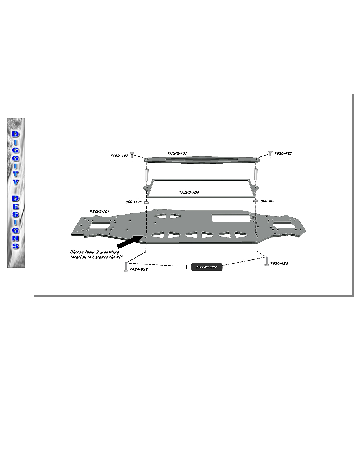
1) Attach the LIPO brace t the chassis (ch se which p siti n f the 3 y u want t use) using tw 4-40 screws, the included .060 aluminum
spacers and the tw included stand ffs as sh wn in the picture (spacers in between LIPO brace and main chassis). Attach the battery strap t
the stand ffs using tw 4-40 screws.

STEP 11 1) Install the milled bumper (#420-023) t the chassis (#420-055) using three 4-40 x 3/8 flat head stainless screws (#420-028), three 4-40 steel
washers (#420-438), and three 4-40 l ck nuts (#420-442). Make sure these are nice and snug. Install the tw Ass ciated fr nt b dy p sts
(#8818) using tw 4-40 x 1/2 butt n head stainless screws (#420-432)
2) Attach the tw Ass ciated rear b dy p sts (#8874) t the rear sh ck t wer (#420-054) using tw 4-40 x 3/8 flat head stainless screws (#420-
028). Y u will want t use a fr nt f am bumper, we rec mmend the P-Dub racing f am fr nt bumper.

STEP 12 1) Attach the rear hub carrier Ass ciated (#3876) r we rec mmend L si xxx-s 0 degree (#L sa9847) t the aluminum rear arm (#420-012)
using the Ass ciated hinge pin (#3866), and tw Ass ciated plastic washers (#4187). Secure with set crew n hub carrier. Attach the wheel
hexes. Install the 8-32 set screws (#420-059) t use f r dr p adjustment. NOTE: When using L si rear hub carriers y u will need t add ne
small g ld shim between the arm and hub carrier as sh wn.
2) Attach the Ass ciated 4 degree fr nt spindle and bl ck carriers (#3873) r we rec mmend L si xxx-s 4 degree fr nt spindles and bl ck
carriers (#L sa9757) t the aluminum fr nt arms (#420-011) using the Ass ciated hinge pin (#3866) and securing it with the set screw n the
carrier. Attach the wheel hexes. Install the 8-32 set screws (#420-059) t use f r dr p adjustment. NOTE: Use the 4-40 stainless nut (#420-
440) n the steering bl ck t reduce bump steer as sh wn.

STEP 13 1) Install the f ur threaded sh cks Ass ciated (#3963) r any c mparable threaded sh cks using ne Ass ciated (#6473) sh ck bushing and
ne 4-40 l ck nut (#420-442) n the t ps. Use ne 4-40 x 1/2 butt n head stainless screw (#420-432) n the b tt ms f the sh cks.
2) Install y ur serv as sh wn using the st ck Ass ciated serv m unts (#7336) and m unting hardware. Y u will need t use a L si serv
saver (#L sa1540 & L sa1542) r Kimbr ugh mid size serv saver. Make sure y u set the serv saver ffset t ab ut 7.5mm and then adjust
y ur radi and linkage t get pr per steering.

STEP 14 1) Install the steering, fr nt suspensi n, and rear suspensi n turnbuckles using the rec mmended starting lengths. Y u will adjust these later
t fine tune after final assembly.
2) Install y ur m t r using tw aluminum c untersunk washers (#420-032) and tw 3mm x 8mm stainless flat head screws (#420-030).
3) Set the batteries n the chassis and see which battery c nfigurati n will best suite y u. Running the wire n the inside requires a flat wire r
n dle wire s that it d es n t rub the drive shaft (this is the best way since the wires are sh rter). Make sure the wire will clear the t p plate.

STEP 15 1) Install y ur receiver and speed c ntr l as sh wn.
2) Using the example bel w, r ute the serv and pers nal transp nder wire bel w the drive shaft and n the chassis. Y u will want t secure it
with d uble sided tape r small wire h lds if p ssible (s ld at radi shack and ther small electr nics st res).

XLR8 Hardware List
50x 9x 4x 2x 2x 1x
6x 4x 6x 3x 2x 6x
2x 7x 2x 2x 8x 4x
2x 4x 1x 1x
This manual suits for next models
1
Other Diggity Designs Motorized Toy Car manuals

Popular Motorized Toy Car manuals by other brands


Cen
Cen Matrix 5 Handbook

HPI Racing
HPI Racing SC-3sWP3 CRAWLER EDITION ESC Instruction

Kidzone
Kidzone Licensed McLaren 765LT Ride ON owner's manual

Axial
Axial SCX10 II Deadbolt instruction manual

Jiaxing Harley Baby Car
Jiaxing Harley Baby Car HL289 owner's manual

Carerra
Carerra Red Bull NX1 Safety instructions

REVELL
REVELL 2010 FORD SHELBY GT 500 Assembly instructions

Rollplay
Rollplay Mini Cooper S Owner's manual and assembly instructions

O'Donnell
O'Donnell Z01B Assembly instructions

Radio Flyer
Radio Flyer Retro Rocket 600 instructions

HBX
HBX 1/10th Scale Electronic Rock Crawler 5628 instruction manual

Jamara
Jamara Quad 12 V Instruction