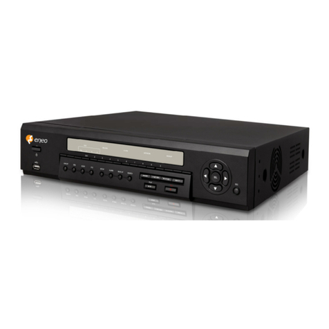
Digi-IT DIS-4000 User manual

DIS-4000
(Standalone Digital Video Recorder)
User’s manual
(Installation and Operation)

Table of Contents
1. Introduction.........................................................................................................................5
Features...................................................................................................................................................5
Contents..................................................................................................................................................6
Parts.........................................................................................................................................................7
Front panel..........................................................................................................................................7
Rear panel .........................................................................................................................................10
Remote control..................................................................................................................................11
2. Connection ........................................................................................................................12
Basic connection overview....................................................................................................................12
Power....................................................................................................................................................13
Camera connection................................................................................................................................14
Monitor connection...............................................................................................................................15
udio input............................................................................................................................................16
udio output..........................................................................................................................................16
..........................................................................................................................................................16
RS-422 device........................................................................................................................................17
RS-485 device........................................................................................................................................17
RS-232C device......................................................................................................................................18
Sensor (D/I)...........................................................................................................................................19
larm (D/O)..........................................................................................................................................20
3. Getting started...................................................................................................................21
Front/rear panel, mouse, and remote control.......................................................................................21
Starting/Stopping the system................................................................................................................21
Starting the system............................................................................................................................21
Stopping the system..........................................................................................................................21
4. Setup.................................................................................................................................23
Overview of each menu.........................................................................................................................23
Menu setup...........................................................................................................................................24
/V.....................................................................................................................................................24
REC.....................................................................................................................................................24
DISPL Y..............................................................................................................................................26
2

EVENT................................................................................................................................................26
COMM...............................................................................................................................................28
MISC...................................................................................................................................................30
SYSTEM..............................................................................................................................................31
EXIT....................................................................................................................................................33
Setting the date and time......................................................................................................................34
Setting and changing the password.......................................................................................................34
5. ive....................................................................................................................................35
LIVE mode..............................................................................................................................................36
To switch to the multiple screen mode.............................................................................................36
To use the sequence mode................................................................................................................36
To switch positions between screens................................................................................................37
To use the zoom mode......................................................................................................................37
To use the freeze feature...................................................................................................................37
PIP (Picture in picture) mode.................................................................................................................38
To display or hide the small screen:...................................................................................................38
To move the small screen:.................................................................................................................38
To view other channels:.....................................................................................................................39
Other features in the Live mode............................................................................................................39
To use the sensor clear feature .........................................................................................................39
To use the audio source from the camera site..................................................................................40
6. Recording...........................................................................................................................41
Schedule recording................................................................................................................................41
Schedule setup..................................................................................................................................41
Holiday setup.....................................................................................................................................43
Other setup........................................................................................................................................45
Event recording.....................................................................................................................................46
Emergency recording.............................................................................................................................47
7. Search and playback..........................................................................................................48
Search by date.......................................................................................................................................48
Search by Event.....................................................................................................................................49
Log history.............................................................................................................................................50
Playback.................................................................................................................................................51
Using the buttons (on the front panel, remote control, screen)........................................................51
Using the Jog-shuttle.........................................................................................................................52
3

8. PTZ.....................................................................................................................................53
Starting the PTZ menus..........................................................................................................................53
Using the Pan, Tilt, and Zoom features..................................................................................................54
djusting the focus and speed...............................................................................................................54
Creating and saving a preset..................................................................................................................54
Go to the preset.....................................................................................................................................54
Remove the preset................................................................................................................................55
9. Backup...............................................................................................................................56
CD/DVD..................................................................................................................................................56
USB........................................................................................................................................................57
Network.................................................................................................................................................58
10. Factory default.................................................................................................................59
Factory default reset..............................................................................................................................59
Emergency restoration mode................................................................................................................59
11. Installing HDD..................................................................................................................60
dding a new HDD.................................................................................................................................60
Formatting a new HDD..........................................................................................................................61
12. Selecting a device on stack...............................................................................................63
133. Using RMS......................................................................................................................64
Appendix A- Specifications.....................................................................................................92
Hardware...............................................................................................................................................92
Functional I............................................................................................................................................93
Functional II...........................................................................................................................................94
Electrical Characteristics........................................................................................................................94
Appendix A - Dimensions.......................................................................................................95
Appendix B - Factory default value........................................................................................96
Appendix C - Buzzer codes.....................................................................................................99
Appendix D - Recording table ..............................................................................................100
Appendix E - User account and menu access level................................................................101
...........................................................................................................................................101
Revision history...................................................................................................................102
4

1. Introduction
Features
The DIS-4000 is a standalone DVR (Digital Video Recorder), providing you 16 channels of video with 480
fps at CIF. For many reasons, the DIS-4000 is an excellent choice for your business surveillance and
security camera systems. Below are some key features of your device:
Various split modes: You can watch videos with various (1/4/6/8/9/13/16) split modes according to
your needs and given purposes.
Easy setup and operation: You can customize settings easily with user-friendly menus, and control
the device with three different interfaces: the front panel, the remote control, and the mouse.
Easy and quick backup: You can efficiently backup data to other storage devices using a CD/DVD
writer, a USB memory, and also via the network.
Easy search and playback: You can easily search and control the video playback using the jog-shuttles
on the front panel, as well as video control buttons.
Emergency record mode: You can immediately start recording videos and search for them later,
using the emergency record feature.
Data restoration: You can turn on the system in the Emergency restoration mode and manually
restore the data or upgrade the system.
Automatic video monitor setting: When the system turns on, it detects the connected video monitor
and automatically sets the video mode according to the available video type.
Multiple user interfaces: You can control the device by using the remote control, Jog-shuttle,
Navigation keys, and USB mouse.
Network: You can access the live video and recorded video via Ethernet by using the web browser.
Event: You can set various types of events and how to react to these events.
Multi- anguage: DIS-4000 supports multi-languages operation interfaces.
5

Contents
Upon unpacking the box, you will find several items ranging from small parts to big components as
below. Be sure to check if all the items are included, and report any missing parts or defects to the
personnel in charge.
Standalone DVR unit -----------------------------------------------------------------1
Remote control ------------------------------------------------------------------------1
S T Data Cable -----------------------------------------------------------------------2
S T Power Cable ---------------------------------------------------------------------1
DC 12V 6 Power adaptor ----------------------------------------------------------1
Optical Mouse (USB)------------------------------------------------------------------1
User’s manual---------------------------------------------------------1
8RC (F) to D-SUB 9Pin(M) cable for audio ------------------------------------2
battery ------------------------------------------------------2
Joint screws for HDD ----------------------------------------------------------------12
6

Parts
You can control the device using three input systems: Buttons on the front panel, Buttons on the remote
control, and the mouse.
In this section, you will learn basic functions of the buttons on the front/rear panel and the remote
control. Learn how to operate the system using the buttons and familiarize yourself with them.
Front panel
The buttons and the jog-shuttle on the front panel serve as controllers for using menus and taking
actions. Refer to the picture below for the locations of the buttons on the panel.
Channel
Selects and shows each video channel in the full screen mode, corresponding to its channel number.
It (1-10) inputs numbers, such as a password (10 represents the number 0). Each LED indicates the
status of video loss.
Mode
IVE: Returns to the LIVE mode.
SETUP: ccesses the SETUP menu.
SEARCH: ccesses the SE RCH screen.
PTZ: Displays the virtual control on the screen, for controlling and customizing the camera PTZ
actions.
Function
ZOOM IN / DISP AY: Zooms in with the virtual PTZ control on. / Selects the screen layout. When
selected, the screen splits into 4/6/8/9/13/16.
7
Power
Function
Jog-shuttle
USB port
CD/DVD-RW
Rom Navigation keys
Channel
Mode

ZOOM OUT / SEQUENCE: Zooms out with the virtual PTZ control on. / Starts or stops the SEQUENCE
mode. The screen shows all video channels in the order of channel number in the Live mode.
FOCUS NEAR / FREEZE: djusts the aperture of a PTZ camera with the virtual PTZ control on. /
Freezes or resumes the screens in the LIVE mode.
FOCUS FAR / ZOOM: djusts the aperture of a PTZ camera with the virtual PTZ control on. /
Magnifies the view 2 times or returns to the original view (in the full screen mode only).
PIP: Shows or hides the PIP (Picture in picture) screen in the full screen mode.
AUDIO: Displays the audio control box for audio output.
P AY: Directly plays the latest (previous 5 minutes) recorded video in the LIVE mode or resumes the
playback.
PAUSE: Pauses the video playback.
STOP: Stops the video playback and returns to the LIVE mode.
REW: Rewinds the video in the Playback mode.
FF: Fast-forwards the video in the Playback mode.
EMERGENCY: ccesses or stops the EMERGENCY record mode. When pressed together with the
Power button, turns on the system in the Emergency restoration mode.
Operation
Jog-shuttle: Serves as fast-forward and rewind control in the SE RCH mode. It helps you search and
playback the video more accurately and efficiently.
Navigation: Navigates through menus or items on the screen.
OK: Selects and confirms the input.
ETC
Power: Turns the unit on or off (with the power switch on the rear panel on).
USB port: Connects a USB device, such as a mouse or a memory disk, to the unit.
Status indicators: Indicates operating status as follows:
POWER: The system is powered on or off.
ACTIVE: The network connection is made or not.
HDD: Data is being read or written on the hard disk drive.
8

ear panel
The switches, connectors, plugs, and sockets on the rear panel are mainly used to connect the DVR
device to other devices, such as cameras and a TV monitor. Refer to the picture below for the locations
of each part on the panel.
Power switch: Turns the unit on or off.
Power socket: Connects the power adopter to a power source.
USB port: Connects a USB device, such as a mouse or a memory disk, to the unit.
Ethernet: Connects the device with the Ethernet port cable.
Audio out ( /R): Connects the unit with audio output devices, such as speakers.
VGA connector: Connects a VG monitor to the unit.
S-video: s a video output connector, connects to a monitor with the S-Video terminal.
TERM/JTAG: Used when the unit needs to be repaired for after sales service.
MODEM: Used when the unit needs to be connected with other device over the RS-232C serial
communications.
TV OUT: Connects the DVR unit with a monitor.
SPOT OUT: Spot out the selected video channel of the 16 channels.
DEFAU T: Clears the sensor and alarm system.
AUDIO IN 1-4/5-8/9-12/13-16: s audio input connectors, connect to cameras.
RS-422/485 and RS-232C: Used for camera PTZ controls. But you are not allowed to use two ports at
the same time.
DIGITA IN: Used for connecting the sensor and relay type.
DIGITA OUT: Used for connecting the sensor and relay type.
VIDEO IN 1-4/5-8/9-12/13-16: s video input connectors, connect to cameras.
OOP OUT 1-4/5-8/9-12/13-16: Outputs each video channel.
9

emote control
The buttons on the remote control serve as controllers for using menus and taking specific actions. Most
of the buttons were covered under Front panel section and they work the same as the ones on the front
panel. Refer to the picture below for the locations of the buttons on the remote control.
MENU: ccesses or exits the SETUP menu.
Skip ( ): Skips the video playback
backwards by ten seconds.
Skip back ( ): Skips the video playback by
ten seconds.
+ / -: Zooms in or out with the virtual PTZ
control on.
DEV: Selects one device to control when
several DIS-4000 devices are stacked up in
one place.
NEAR: djusts the focus of a PTZ camera with
the virtual PTZ control on.
FAR: djusts the focus of a PTZ camera with
the virtual PTZ control on.
FU : Selects the screen layout (in the LIVE
and the SEQUENCE mode only). When
selected, an image of one channel occupies
the screen entirely.
4-SP IT: When selected, the screen splits into
4.
9-SP IT: When selected, the screen splits into
9.
16-SP IT: When selected, the screen splits
into 16.
10
S EA RC H
M EN U
E N TE R
1234
5678
1 01 11 2
1 31 41 51 6
9
F UL L4 -S P LIT9- SP LIT
A U D
D EV
NE A RNE A R
F AR
F RE E ZE
S E Q UE NC E
Z O O M
P IP E M ER G E NC
PT Z
1 6- SP LI T
0

2. Connection
Basic connection overview
Connect security cameras with your DIS-4000 and then plug it into your TV monitor. You can instantly
view the live or recorded video on your monitor. lso, various accessories can be connected to the DIS-
4000 unit with matching cables. Refer to the following diagrams of each connection to understand how
the system works. Learn how to connect devices to the unit.
11

Power
Connect the power adopter to a power source.
Note
i
Input Voltage: 12 VDC (12V DC 6 adaptor is needed.)
Current: 3200 m
Power Consumption (max ±5%): 38.4 W
Note
i
When plugging the power jack into the device, use the provided clip on the back panel for
fixing the jack. Failure to this often causes the loss of data and power supply. Refer to the
image above.
12
0
I

Camera connection
Connect the camera to the Video input connectors on the back panel using 75 ohm video coaxial cables
with a BNC connector. Each video channel input among these connections can be looped to other
equipments as CRT monitor through Video Loop out connectors. The DVR unit can be used with either
NTSC or P L equipment.
Caution
!
The Loop out connectors are auto terminated. Do NOT connect a cable to the Loop out
connectors unless it is connected to a terminated device because it will cause poor
quality video.
Note
i
You cannot use NTSC and P L equipment together.
13

Monitor connection
Connect the main monitor to the TV Out or S-VIDEO connectors on the back panel.
VG connector is provided so that you can use a standard, multi-sync computer monitor as your main
monitor. Use the cable supplied with your monitor to connect it to the DVR unit. Spot out connector is
provided for displaying selected one channel among the 16 channels.
Note
i
The TV Out and S-VIDEO connectors may be connected to individual monitors for
simultaneous operation.
Note
i
The supported video signal resolution is 1024x768 and timing is 60Hz.
14

Audio input
Connect the audio input device such as a microphone to 8RC (F) to D-SUB 9Pin(M) cables.
Note
i
udio input range: 1.0/1.5 (Typical/Max) Vp-p
Audio output
Connect to the audio input device such as a speaker. Plug one end of the cable into the UDIO L and
UDIO R sockets on the DVR unit, and plug the other end into the matching sockets on your speaker.
15
udio Input 1
udio Input 2
udio Input 16
°
°
°
°
°
°
°
°
°
°
°
°
L
R

S-422 device
The RS-422 serial port consists of RX+, RX-, TX+, and TX- as following the following image.
S-485 device
The RS-485 serial port consists of TRX+ and TRX- as following the following image.
16
RX TX G G
TX+
TX-
DEVICE 1
DEVICE 2
RX+
RX-
TX+
TX-
RX+
RX-
RS-232
RS-485
RX+ TRX+
RX- TRX -
TRX+
TRX-
TRX+
TRX-
TRX+
TRX-
DEVICE 1
DEVICE 2
DEVICE 3
RX TX G G
RX+ TRX+
RX- TRX -
RS-232
RS-485
DIS-4000

S-232C device
RS-232C Terminal Block consists of RX, TX, and GND as following the following image.
17
RX TX G G
RX+ TRX+
RX- TRX -
RS-232
RS-485
TX
RX
G
DEVICE 1

Sensor (D/I)
There are two sensor interface types – Voltage Type and Relay Type. The interface type can be
controlled by the software. Before connecting sensors, check driving voltage and output signal type of
the sensor. Since the connection is different according to sensor type, be careful to connect the sensor.
Signal Description
COM Connect (-) cable of electronic power source for sensors to this port as shown
in the circuit above.
DI1~DI16 Connect output of sensors for each port as shown in the circuit above.
Note
i
Input range: TTL level 4.5V threshold, Max 500m
18
+5V
+5V
DI 1
DI 16
COM
----------
DI 1
DI 16
COM
----------
+
-
Relay Type Voltage Type
+5VDC~+24VDC
+ -
+-
Output of
Sensor 1
Output of
Sensor 16
Output of
Sensor 16
Output of
Sensor 1
Internal Internal
+
+
-
-

Alarm (D/O)
Only the Relay type is supported.
Relay Rating: Max 500m @24V C or 1 @12VDC
Caution
!
Do not exceed the maximum Relay rating.
19
DO 1
DO 16
COM
----------
Relay Type
X
Max 12VDC 1
or 24V C 500m Power
Device
Device
Internal

3. Getting started
Front/rear panel, mouse, and remote control
Basic functions of each button or key are covered in the previous section.
Starting/Stopping the system
Starting the system
Turn on the POWER switch on the rear panel.
The system loading begins and you can see the whole booting process on the screen. ll sixteen
video channels appear on the screen and the booting message is displayed.
Press the SETUP button on the front panel or the MENU button on the remote control to log in. If
your mouse is ready, you can also right-click on the screen and select SETUP.
Select a user (Admin, Operator, or Viewer) account from the User drop-down list.
Enter the password and then, select the OK button.
Note
i
If you turn off the power by using the POWER button on the front panel, you can turn on
by using the POWER button on the front panel.
Note
i
When a power failure occurs while the system is running and electric power is supplied
again, the system will turn on though you don’t press the POWER button.
Note
i
remote control cannot turn on the power
Stopping the system
1) Press the POWER button on the front panel or the remote control. You can also right-click
on the screen and select SHUTDOWN.
Select the tick button (√).
Enter the password and then, select the tick button (√) (if necessary).
<< To reboot the system, select REBOOT in step 1) first and continue.
20
Table of contents
Popular DVR manuals by other brands
Clinton Electronics
Clinton Electronics CE-RP2 instruction manual
Motorola
Motorola DCT2500 quick start guide
urmet domus
urmet domus 1093/040 instruction manual
Prestigio
Prestigio RoadRunner 525 manual
Bosch
Bosch DIP-73GC-16HD installation manual
Dedicated Micros
Dedicated Micros TransVu Express quick start guide
