Watchport Installation Guide (90000406 Rev. H) – Page 2
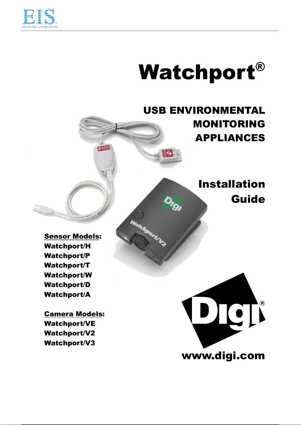
Installing Watchport
Camera Drivers
NOTE: If any Watchport Camera drivers are already installed on your system, you MUST uninstall them
before continuing with these installation instructions. Also, the two sets of drivers (one for DirectShow and
one for TWAIN and AVI) are mutually exclusive; you may install one OR the other, but not both.
If you are using DirectShow (DirectX), follow the instructions below. If you are using TWAIN or AVI, go
to “TWAIN and AVI Drivers” on page 3.
DirectShow (DirectX) Drivers
You may want to check that you have the most recent version of DirectX before continuing with these
installation instructions.
For Win ows XP, 2000, an 2003 Server Users
Drivers for DirectShow (DirectX) are on the “DirectShow Driver and Manual” CD. Note that you must be
logged into an account with administrator privileges.
1) Insert the “DirectShow Driver and Manual” CD version 2.90 or above into your CD-
ROM drive.
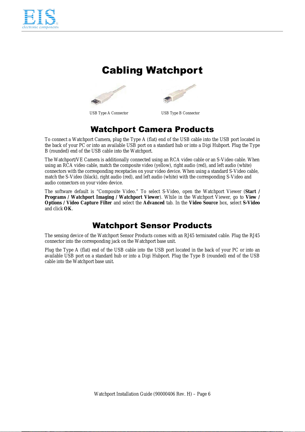
2) Plug in the Watchport Camera. (See “Cabling Watchport” on page 6).
3) When the Found New Hardware screen for the Watchport USB Loader software
appears, choose option a) or option b):
a) Specify the location of the drivers and click Next.
b) Install from a list or specific location and click Next. The subsequent screen
allows you to search removable media, type the location path, or browse to locate the
drivers on your CD-ROM drive. Use one of these methods to locate the drivers and
click Next.
4) Windows may warn that the software “has not passed Windows Logo testing.” Click
Continue Anyway to continue with driver installation.
5) When the Found New Hardware Wizard finishes installing the Watchport USB
Loader software, click Finish.
6) Wait for the second Found New Hardware screen (for the Watchport Camera
software) to appear. When it does, again choose option a) or option b) as described in
step 3.
7) Windows may warn that the software “has not passed Windows Logo testing.” Click
Continue Anyway to continue with driver installation.
8) When the Found New Hardware Wizard finishes installing the Watchport USB
Camera software, click Finish.
Your Watchport Camera is now ready to use. To verify installation you may start the Watchport Viewer
(found in Start/Programs/Watchport imaging/Watchport Viewer).
The Watchport Viewer defaults to activating the camera (in Options/Preview). You can open a Properties
screen through Options/Video Capture Filter and adjust brightness, sharpness, contrast, color,
compression, etc.