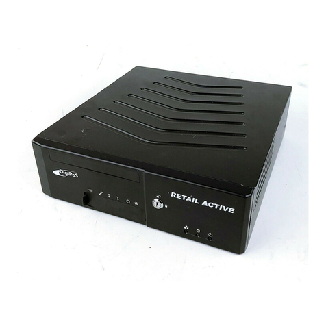
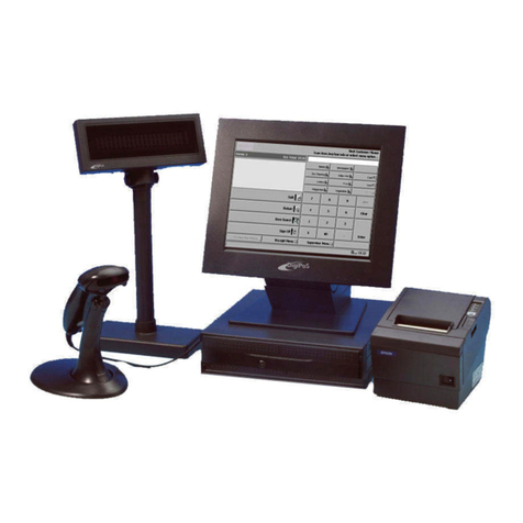
DigiPos RB1 User manual

Manual
Manual Version 1.0
July 2005
N13798

DigiPoS Retail Blade™Manual
Revision History
Revision
Number Date Details of
Updates
Person
Responsible
Signature
1.0 October 2005 Initial Release Jonathan Croft
Page2 of 100
Copyright © 2005 DigiPoS Systems Group

DigiPoS Retail Blade™Manual
USER’S NOTICE
No part of this manual, including the products and software described in it, may be
reproduced, transmitted, transcribed, stored in a retrieval system, or translated into any
language in any form or by any means, except documentation kept by the purchaser for
backup purposes, without the express written permission of DigiPoS Systems.
DigiPoS Systems provides this manual “AS IS” without warranty of any kind, either
express or implied, including but not limited to the implied warranties or conditions of
merchantability or fitness for a particular purpose. In no event shall DigiPoS Systems, its
directors, officers, employees or agents be liable for any indirect, special, incidental, or
consequential damages (including damages for loss of profits, loss of business, loss of
use or data, interruption of business and the like), even if DigiPoS Systems has been
advised of the possibility of such damages arising from any defect or error in this manual
or product.
Specifications and information contained in this manual are provided for informational
use only, and are subject to change or update at any time without notice, and should not
be construed as a commitment by DigiPoS Systems. DigiPoS Systems assumes no
responsibility or liability for any errors or inaccuracies that may appear in this manual,
including the products and software described in it.
Updates to this manual and additional information may be found on the Internet at
http://www.digipos-systems.com/
For any drivers associated with this DigiPoS, please contact your supplier/distributor or
you can find the latest versions available for download on the Internet at
http://www.digipos-systems.com/
FCC Radio Frequency Interference Statement
This equipment has been tested and found to comply with the limits for a class A digital
device. These limits are designed to provide reasonable protection against harmful
interference when the equipment is operated in a commercial environment. This
equipment generates, uses and can radiate radio frequency energy and, if not installed
and used in accordance with the instruction manual, may cause harmful interference to
radio communications. Operation of this equipment in a residential area is likely to cause
harmful interference, in which case the user will be required to correct the interference at
this own expense.
Notice
The changes or modifications not expressly approved by the party responsible for
compliance could void the user’s authority to operate the equipment.
All brand names and registered trademarks mentioned in this manual are the property of
their respective owners and their use here is for reference purposes only.
Page3 of 100
Copyright © 2005 DigiPoS Systems Group

DigiPoS Retail Blade™Manual
SAFETY INSTRUCTIONS
•Always read the safety instructions carefully.
•Keep this Manual for future reference.
•Keep this equipment away from humidity and dust.
•Lay the equipment on a reliable flat surface before setting it up.
•The openings on the enclosure are for air convection, hence protecting the equipment from
overheating. DO NOT COVER THESE OPENINGS. For a more detailed explanation about
ventilation requirements, please check the appropriate section within this document.
•Make sure the voltage of the power source (mains) conforms within the permitted range
before connecting the equipment to the power inlet. If you have any doubts, please contact a
licensed electrician to advise you accordingly.
•Place the power cord in such a way that people cannot step on it. Do not place anything over
the power cord.
•ALWAYS shut down the operating system and disconnect the unit from any power sources
before removing any connections (Keyboard, Mouse, etc..) or opening up the unit to fit
additional cards and or devices.
•ALWAYS shut down the operating system and disconnect the unit from any power sources
before removing the front cover or attempting to remove the Blade or the Hard Drive.
•All cautions and warnings on the equipment should be noted and adhered to.
•Never pour any liquid into any openings. This could cause damage or electrical shock.
•If any of the following situations arise, have the equipment checked by qualified service
personnel:
oThe power cord or plug is damaged
oLiquid has penetrated into the DigiPoS Retail Blade™ or the external power supply
oThe equipment has been exposed to moisture
oThe DigiPoS Retail Blade™ is not working well or you can not get it to work according
to the User’s Manual
oThe DigiPoS Retail Blade™ has been dropped and damaged
oThe DigiPoS Retail Blade™ has obvious signs of breakage or physical damage
•Do not leave this DigiPoS Retail Blade™ in a non air-conditioned environment with a storage
temperature above 60ºc (140ºf) as it may damage the equipment.
•For reasons of safety, gloves should be worn when assembling the DigiPoS Retail Blade™
after any work has been carried out.
NOTE
•The technical descriptions, specifications and any associated diagrams or pictures of the
DigiPoS Retail Blade™ are subject to change without notice.
ACHTUNG!
•Wir behalten uns Änderungen der technischen Beschreibungen bzw. Spezifikationen vor.
注意事項
•本說明書所列規格僅供參考, 本公司保留產品修改變更之權利.
•為了您的安全, 拆裝PC內部組件時請戴白手套以防割傷.
Page4 of 100
Copyright © 2005 DigiPoS Systems Group

DigiPoS Retail Blade™Manual
CAUTION
There is a danger of explosion if the CMOS battery is incorrectly replaced.
Replace only with the same or equivalent type of battery. Please Contact your
nearest DigiPoS Systems office for further information and or assistance.
Page5 of 100
Copyright © 2005 DigiPoS Systems Group

DigiPoS Retail Blade™Manual
CONTENTS
REVISION HISTORY ..........................................................................................................2
INTRODUCTION .............................................................................................................11
Key Features ...................................................................................................................................................11
Host.....................................................................................................................................................11
Retail Blade™ Specifications & Options .......................................................................................12
VENTILATION REQUIREMENTS ....................................................................................13
Cavity Size.......................................................................................................................................................13
Enclosed Spaces............................................................................................................................................13
External PSU ...................................................................................................................................................14
Under Counter Mounting ............................................................................................................................15
DigiPoS Brackets...............................................................................................................................15
TECHNICAL SPECIFICATIONS ......................................................................................16
CPU & FSB Clock Speeds............................................................................................................................16
Memory............................................................................................................................................................16
BIOS..................................................................................................................................................................17
South Bridge - Intel ® ICH5........................................................................................................................18
Overview ............................................................................................................................................18
PCI Bus Interface...............................................................................................................................18
Integrated LAN Controller...............................................................................................................18
Integrated Serial ATA Host Controller...........................................................................................18
USB 2.0...............................................................................................................................................19
Interrupt Controller...........................................................................................................................19
High-Precision Event Timers ...........................................................................................................19
1.5 V operation with 3.3 V I/O ........................................................................................................19
Power Management Logic...............................................................................................................19
Enhanced DMA Controller ..............................................................................................................19
Real-Time Clock ................................................................................................................................19
SMBus.................................................................................................................................................19
North Bridge - Intel® 82865GV.................................................................................................................20
Overview ............................................................................................................................................20
Host Interface ....................................................................................................................................20
System Memory Controller..............................................................................................................20
Communication Streaming Architecture (CSA) Interface............................................................21
Hub Interface (HI)..............................................................................................................................21
AGP Interface Support.....................................................................................................................21
Integrated Graphics..........................................................................................................................21
Display Interfaces..............................................................................................................................22
Analogue Display Support...............................................................................................................22
Digital Display Channels..................................................................................................................23
Page6 of 100
Copyright © 2005 DigiPoS Systems Group

DigiPoS Retail Blade™Manual
Onboard Audio ..............................................................................................................................................23
Sound Quality....................................................................................................................................23
Input / Output ...................................................................................................................................23
Architecture .......................................................................................................................................23
Other Features ..................................................................................................................................23
Options ............................................................................................................................................................24
PCI Cards............................................................................................................................................24
Dual VGA Cards ................................................................................................................................24
RAID....................................................................................................................................................24
Important Notes.............................................................................................................................................24
THE SYSTEM....................................................................................................................25
Front Panel Orientation – with Cover Fitted ..........................................................................................25
Front Panel Orientation – with Cover Removed....................................................................................26
Rear Panel Orientation.................................................................................................................................27
Internal System Orientation........................................................................................................................28
Removing the Blade from the Host...........................................................................................................29
Re-fitting the Blade in the Host .................................................................................................................30
The Retail Blade™ Thermostatic Cooling Module & CPU ..................................................................31
Removing the CPU Thermostatic Cooling Module and the CPU..............................................31
Motherboard Jumper Settings...................................................................................................................36
Jumpers..............................................................................................................................................36
Power Distribution Board Orientation......................................................................................................36
Motherboard Orientation............................................................................................................................37
CF Daughter Board Orientation ................................................................................................................37
I/O Interfaces & Power Connectors ..........................................................................................................38
RS232 Standard Serial Ports............................................................................................................38
Parallel Port........................................................................................................................................38
USB Ports (Standard) ........................................................................................................................39
Retail USB Ports (Powered)..............................................................................................................39
PS / 2 Keyboard & Mouse Ports .....................................................................................................40
Windows Shortcut Keys....................................................................................................................40
LAN Connector..................................................................................................................................41
VGA Connector.................................................................................................................................42
Hosiden Connector...........................................................................................................................42
Power Supply Connector .................................................................................................................43
2.5mm Barrel Connectors................................................................................................................43
Cash Drawer Ports ............................................................................................................................43
Page7 of 100
Copyright © 2005 DigiPoS Systems Group

DigiPoS Retail Blade™Manual
POWER DISTRIBUTION ..................................................................................................44
Overview..........................................................................................................................................................44
Powered Port Over Current Protection....................................................................................................45
Power Board Configuration.........................................................................................................................45
Applications ....................................................................................................................................................45
Typical Voltage Requirements ...................................................................................................................46
COM Port Voltage Selection ......................................................................................................................46
Cash Drawer Voltage Selection .................................................................................................................47
Continuous and Peak Current Capacity...................................................................................................47
ONBOARD DIAGNOSTICS FOR THE DIGIPOS RETAIL BLADE™ ..............................48
Diagnostic Overview.....................................................................................................................................48
Diagnostic Procedure ...................................................................................................................................48
Diagnostic Program ......................................................................................................................................49
Temperature Status ..........................................................................................................................50
Fan Speeds ........................................................................................................................................50
System Voltages................................................................................................................................50
CPU Status .........................................................................................................................................50
IDE.......................................................................................................................................................51
SATA ...................................................................................................................................................51
USB......................................................................................................................................................52
I/O Memory .......................................................................................................................................52
Parallel Port........................................................................................................................................53
Serial Ports .........................................................................................................................................53
Integrated Cash Drawer...................................................................................................................55
I/O Ports .............................................................................................................................................55
PCI.......................................................................................................................................................56
Airflow.................................................................................................................................................56
Remote System Connection........................................................................................................................57
Select System ....................................................................................................................................57
Alert Functions...............................................................................................................................................60
Add Alert............................................................................................................................................60
View Alert History..............................................................................................................................61
Page8 of 100
Copyright © 2005 DigiPoS Systems Group

DigiPoS Retail Blade™Manual
BIOS SET-UP OVERVIEW................................................................................................62
Main BIOS Screen..........................................................................................................................................63
Standard CMOS Features............................................................................................................................64
IDE Options Sub Menus ..................................................................................................................66
Advanced BIOS Features.............................................................................................................................67
Hard Disk Boot Priority Sub Menu..................................................................................................69
Advanced Chipset Features........................................................................................................................70
Integrated Peripherals..................................................................................................................................72
OnChip IDE Device Sub Menu .......................................................................................................74
Onboard Device Sub Menu.............................................................................................................76
Super IO Device Sub Menu.............................................................................................................77
Power Management Setup..........................................................................................................................79
PnP/PCI Configurations................................................................................................................................81
PC Health Status............................................................................................................................................83
Frequency/Voltage Control ........................................................................................................................85
Operating System Dependant Settings...................................................................................................86
DOS.....................................................................................................................................................86
Windows 95 & NT.............................................................................................................................87
Windows 98, Me, 2000 & Xp (including Xp Embedded and Xp Embedded for POS) ..........87
FAULT DIAGNOSIS.........................................................................................................88
Power Up Test Sequence ............................................................................................................................89
Input / Output Port Testing ........................................................................................................................90
PS/2 Keyboard Port ..........................................................................................................................90
PS/2 Mouse Port ...............................................................................................................................90
COM Ports .........................................................................................................................................90
VGA Port ............................................................................................................................................90
LAN Port.............................................................................................................................................91
Parallel Port........................................................................................................................................91
RJ12 Cash Drawer Connectors .......................................................................................................91
Sound Connectors ............................................................................................................................91
USB Connectors ................................................................................................................................91
Powered Port Testing...................................................................................................................................92
Voltage Level Checking ...................................................................................................................92
Peripheral Component Check ....................................................................................................................93
Page9 of 100
Copyright © 2005 DigiPoS Systems Group

DigiPoS Retail Blade™Manual
1st Level Fault Finding...................................................................................................................................94
System Does Not Boot.....................................................................................................................94
No VGA Output ................................................................................................................................94
Compact Flash failure.......................................................................................................................94
Hard disk failure ................................................................................................................................94
CD ROM Failure................................................................................................................................95
COM port failure...............................................................................................................................95
Parallel Port Failure...........................................................................................................................95
Onboard LAN Failure.......................................................................................................................95
System Hold or Freeze.....................................................................................................................95
Test Sheet Completion ................................................................................................................................96
TEST SHEET.....................................................................................................................97T
WARRANTY POLICY .......................................................................................................99
DIGIPOS SYSTEMS GLOBAL OFFICE LOCATIONS ...................................................100
Page10 of 100
Copyright © 2005 DigiPoS Systems Group

DigiPoS Retail Blade™Manual
Introduction
Congratulations on the purchase of your DigiPoS Retail Blade™ System!
You are now the owner of a state-of-the-art DigiPoS Retail Blade™ System. The DigiPoS
Retail Blade™ System is a solution that offers unparalleled features, speed and
performance combined with exceptional reliability. It is also a PC that is unrivalled by
other conventional Pentium 4 based PCs within the EPoS industry.
Key Features
Host
Component Description
Serial Ports
4 Standard RS232 COM Ports (9 Pin D-Sub Connectors)
IRQ Selector by BIOS setup (Jumper-less)
DC 0 / 5 / 12 / 24v output on pin 9 by jumper selector
Each output voltage protected using POLYFUSE® technology
USB Ports
6 USB 2.0 Ports consisting of:
Four Retail USB Powered Ports (1 x 24v, 2 x 12v, 1 x 5v)
Each output voltage protected using POLYFUSE® technology
2 x Easy access covered front USB ports
Parallel Port 1 x 25 Pin D-Sub connector
Keyboard & Mouse Ports PS/2 (Colour Coded)
Network (LAN) Port Standard RJ45 connection
Audio Connections Rear: MIC in, Audio in & Audio Out
Front: MIC in, Audio in & Audio Out
Graphics Output 1 x 15 Pin D-Sub connector
LCD Power Output 2 x 12v DC dipole
Additional Power Output 1 x 24V Hosiden Connector
Cash Drawer Ports 2 x RJ12 Cash drawer ports with status sensor
Warranty 10 Year Limited Warranty (Host Only)
Outer Case Dimensions 273mm(W) x 335mm(L) x 125mm(H)
10.7” (W) x 13.2” (L) x 4.9” (H)
Page11 of 100
Copyright © 2005 DigiPoS Systems Group

DigiPoS Retail Blade™Manual
Retail Blade™ Specifications & Options
Component RB1 RB2 RB3 RB4 RB5 iBox Thin
Client
CPU
(Intel® Socket 478)
2.0Ghz
Celeron
2.4Ghz
Celeron
2.4Ghz
Celeron
2.8Ghz
P4
2.8Ghz
P4
2.0Ghz
Celeron 1Ghz GX
CPU FSB 400Mhz 400Mhz 400Mhz 533Mhz 533Mhz 400Mhz
Main Memory 256Mb up to 2GB (184 Pin DDRAM x 2 slots)
BIOS Award BIOS With Enhanced ACPI 1.0 / PnP / APM / DMI / ESCD /
PCI bus 2.1 / OnNow / DRAM ECC
CACHE Memory
L2 Advanced Transfer
Cache (full-speed)
128Kb 128Kb 128Kb 512Kb 512Kb 128Kb
Main Chipset North Bridge - Intel® 82865GV
South Bridge - Intel ® ICH5
Graphics Intel® 82865GV AGP up to 64MB using Intel® Extreme 2
On Board LAN Intel® Pro/100 VE Ethernet 10/100 Auto Sensing
On Board Audio VIA Vinyl VT1612A AC97 CODEC with Line In/ Line Out / MIC In
Expansion 2 x Standard PCI Slots (3.3V & 5V)
Enhanced PCI IDE On board PCI Bus Master Ultra ATA/100 IDE1/2. Supports Ultra DMA 33/ 66/ 100
SATA 2 x Serial ATA Ports
FDD
(Optional) External USB device
CD ROM
(Optional) Slim 24x CD-ROM or Slim 24x CD-ROM/ CD RW / DVD
Hard Drive Options
(Removable as
standard)
Single 20GB EIDE 5400RPM
Single 40GB EIDE 5400RPM
Single 80GB S-ATA 7200RPM
Twin 80 / 120GB S-ATA 7200RPM With RAID Function
N / A
Compact Flash IDE Type I/ II Bootable
Diagnostics Utility - On-board DigiPoS Remote Real Time Diagnostics
Software -
Cooling 5 Stage Advanced Heat Management with Liquid Cooling
Power Control System side Remote Power On / ATX Trigger Control
Power Supply External 24v 250 Watt DC to ATX Power Inverter
AC Power Source AC 90V to 264V, 60Hz / 50Hz
Operating System
Compatibility
DOS / OS/2 / SCO XENIX / SCO UNIX / NOVELL LINUX / WIN
3.1/95/98/Me/NT4.0/2000/Xp/WePoS/XPe
Operating
Temperature Operating: 0ºC to 40ºC
Storage Temperature Storage: -25ºC to 70ºC
Warranty on Retail
Blade™ 1 to 3 Years Depending on configuration
Page12 of 100
Copyright © 2005 DigiPoS Systems Group

DigiPoS Retail Blade™Manual
Ventilation Requirements
Cavity Size
If the Retail Blade™ is to be located in a cavity, i.e. under the counter, the cavity
dimensions must be a minimum of 450mm (17.7”) long by 400mm (15.7”) wide by
200mm (7.9”) deep (excluding the external PSU). A diagrammatic representation is as
follows:
Although this is the required space, the Retail Blade™ MUST be located centrally to
prevent the airflow from being disrupted through the ventilation holes in the sides or the
rear of the case.
Enclosed Spaces
If the Retail Blade™ is to be located in an enclosed space, i.e. in a closed box or cabinet,
there must be sufficient airflow into and out of the enclosed space. Using the above
cavity space, for example, forced airflow would have to be fitted to prevent the Retail
Blade™ from overheating. As a general rule, the Retail Blade™ requires an airflow
exchange rate of a minimum of 25 CFM (Cubic Feet per Minute) excluding PSU or 30
CFM including PSU when in an enclosed space.
The recommended location for these fans is as follows:
Without External PSU With External PSU
Page13 of 100
Copyright © 2005 DigiPoS Systems Group

DigiPoS Retail Blade™Manual
External PSU
DigiPoS Systems recommends that the external PSU for Retail Blade™ is not situated in
the same space as the Retail Blade™ to minimise heat build up in enclosed spaces.
If this is unavoidable, forced air ventilation must be installed or the cavity size increased
to provide adequate ventilation for the Retail Blade™ & PSU heat dissipation devices. A
diagrammatic representation is as follows showing the new cavity size required and the
positioning of the external PSU:
Warning: Failure to observe the minimum ventilation requirements for the Retail
Blade™ will cause the unit to overheat. This will dramatically affect the performance
of the Retail Blade™ and may cause permanent damage which will not be covered
by the warranty.
Page14 of 100
Copyright © 2005 DigiPoS Systems Group

DigiPoS Retail Blade™Manual
Under Counter Mounting
The Retail Blade™ can be mounted under the counter or on a secure vertical surface to
maximise the available space at the Point of Sale. In order to do this, a special bracket
must be used that has been specifically engineered for the Retail Blade™. This bracket
does not obstruct the ventilation yet still provides a secure mounting without the need
for drilling holes in the case which will void the warranty.
DigiPoS Brackets
To fit the bracket, simply remove the four small black case screws on the side of the
Retail Blade™ and offer up the bracket to the Retail Blade™. Then, using the new longer
screws that came with the bracket, attach the bracket to the Retail Blade™ and secure in
position.
Give due consideration to the mounting of the Retail Blade™ so that the Blade can still
be extracted without having to dismantle to bracket assembly.
The External PSU has mounting holes pre-formed in its case and does not require any
special brackets.
Please contact you’re nearest DigiPoS Systems Office for further details and availability
on these brackets.
Page15 of 100
Copyright © 2005 DigiPoS Systems Group

DigiPoS Retail Blade™Manual
Technical Specifications
CPU & FSB Clock Speeds
The Central Processing Unit or CPU fitted in your Retail Blade™ will depend greatly on
what particular model of Retail Blade™ you have.
Component RB1 RB2 RB3 RB4 RB5 iBox Thin
Client
CPU
(Intel® Socket 478)
2.0Ghz
Celeron
2.4Ghz
Celeron
2.4Ghz
Celeron
2.8Ghz
P4
2.8Ghz
P4
2.0Ghz
Celeron 1Ghz GX
CPU FSB 400Mhz 400Mhz 400Mhz 533Mhz 533Mhz 400Mhz
System FSB 200Mhz 200Mhz 200Mhz 200Mhz 200Mhz 200Mhz
The thermal transfer medium between the CPU and the cooling assembly is a
specific type of industrial silicone designed to withstand the more aggressive
environments found within a point of sale installation. We therefore recommend that
only DigiPoS Systems or authorized agents for DigiPoS Systems attempt to remove
the CPU cooling assembly. Failure to comply with this notice shall void all
warranties.
Memory
Each DigiPoS Retail Blade™ can be fitted with two modules of memory. Commonly
referred to as DDR (Double Data Rate) memory, the specifications for this type of
memory is as follows:
Pins 184 Pin Gold
Type SDRAM (Synchronous Dynamic Random Access Memory)
Sizes 256Mb, 512Mb, 1Gb & 2Gb
(Single module or matched Pair)
Clock Speed 266 / 333 / 400Mhz (System FSB x 2)
Using inappropriate types of memory or unmatched pairs of memory may
significantly degrade the performance of your DigiPoS and also void all warranties.
Page16 of 100
Copyright © 2005 DigiPoS Systems Group

DigiPoS Retail Blade™Manual
BIOS
The BIOS is discussed in greater detail later on in this manual.
Page17 of 100
Copyright © 2005 DigiPoS Systems Group

DigiPoS Retail Blade™Manual
South Bridge - Intel ® ICH5
Overview
The ICH5 provides extensive I/O support. Functions and capabilities include:
• PCI Local Bus Specification, Revision 2.3 with support for 33 MHz PCI operations.
• 2 x PCI slots
• ACPI power management logic support
• Enhanced DMA controller, interrupt controller, and timer functions
• Integrated IDE controller supports Ultra ATA 100/66/33
• Integrated SATA controller
• USB host interface with support for eight USB ports
• Integrated LAN controller
• Integrated ASF controller
• System Management Bus (SMBus)
• Supports Audio Codec ‘97
PCI Bus Interface
•Supports PCI Revision 2.3 Specification at 33 MHz
•Support for 44-bit addressing on PCI using DAC protocol
Integrated LAN Controller
•Integrated ASF Management Controller
•WfM 2.0 and IEEE 802.3 Compliant
•LAN Connect Interface (LCI)
•10/100 Mbit/sec Ethernet Support
•Compliance with Advanced Configuration and Power Interface and PCI Power
Management standards
•Support for wake-up on interesting packets and link status change
•Support for remote power-up using Wake on LAN* (WOL) technology
•Deep power-down mode support
•Support of Wired for Management (WfM) Revision 2.0
•Backward compatible software with 82550, 82557, 82558 and 82559
•TCP/UDP checksum off load capabilities
•Support for Intel’s Adaptive Technology
•Peer to Peer Support
•Half/ Full duplex capability
•Supports Full Duplex Flow Control (IEEE 802.3x)
Integrated Serial ATA Host Controller
•Independent DMA operation on two ports
•Data transfer rates up to 1.5 Gb/s (150 MB/s)
Page18 of 100
Copyright © 2005 DigiPoS Systems Group

DigiPoS Retail Blade™Manual
USB 2.0
•Includes 4 UHCI Host Controllers
•Includes 1 EHCI Host Controller that supports all eight ports
•Includes 1 USB 2.0 high-speed debug port
•Supports wake-up from sleeping states S1–S5
•Supports legacy Keyboard/ Mouse software
Interrupt Controller
•Supports up to 8 PCI interrupt pins
•Supports PCI 2.3 Message Signaled Interrupts
•Two cascaded 82C59 with 15 interrupts
•Integrated I/O APIC capability with 24 interrupts
•Supports Front Side Bus interrupt delivery
High-Precision Event Timers
•Advanced operating system interrupt scheduling
1.5 V operation with 3.3 V I/O
•5V tolerant buffers on IDE, PCI, USB Over current and Legacy signals
Power Management Logic
•ACPI 2.0 compliant
•ACPI-defined power states (C1, S3–S5)
•ACPI Power Management Timer
•PCI PME# support
•SMI# generation
•All registers readable/restorable for proper resume from 0 V suspend states
•Support for APM-based legacy power management for non-ACPI
implementations
Enhanced DMA Controller
•Two cascaded 8237 DMA controllers
•PCI DMA: Supports PC/PCI — Includes two PC/PCI REQ#/GNT# pairs
•Supports LPC DMA
•Supports DMA Collection Buffer to provide Type-F DMA performance for all
DMA channels
Real-Time Clock
•256-byte battery-backed CMOS RAM
•Integrated oscillator components
SMBus
•Provides independent manageability bus through SMLink interface
•Supports SMBus 2.0 Specification
•Host interface allows processor to communicate via SMBus
•Slave interface allows an internal or external Microcontroller to access system
resources
•Compatible with most 2-Wire components that are also I2C compatible
Page19 of 100
Copyright © 2005 DigiPoS Systems Group

DigiPoS Retail Blade™Manual
North Bridge - Intel® 82865GV
Overview
•Host Interface
•System Memory Interface
•Hub Interface
•Communications Streaming Architecture (CSA) Interface
•Multiplexed AGP and Intel® DVO Interface
Host Interface
•Intel® Pentium® 4 processors with 512Kb L2 cache on 0.13 micron process /
Pentium 4 processor on 90 nm process
•64-bit FSB frequencies of 400 MHz (100 MHz bus clock), 533 MHz (133 MHz
bus clock), and 800 MHz (200 MHz bus clock). Maximum theoretical BW of 6.4
GB/s.
•FSB Dynamic Bus Inversion on the data bus
•32-bit addressing for access to 2 GB of memory space
•12-deep In Order Queue
•AGTL+ On-die Termination (ODT)
•Hyper-Threading Technology
System Memory Controller
•Dual-channel (128 bits wide) DDR memory interface
•Single-channel (64 bits wide) DDR operation supported
•Symmetric and asymmetric memory dual-channel upgrade
•Non-ECC, un-buffered DIMMS only
•Up to 2 GB system memory
•Supports up to 16 simultaneously-open pages (four per row) in dual-channel
mode and up to 32 open pages in single-channel mode
•4-KB to 64-KB page sizes (4 KB to 32 KB in single-channel, 8 KB to 64 KB in
dual-channel)
•Supports opportunistic refresh
•Suspend-to-RAM support using CKE
•SPD (Serial Presence Detect) Scheme for DIMM Detection supported
•Supports selective Command-Per-Clock (selective CPC) Accesses
•DDR (Double Data Rate type 1) Support
oSupports maximum of two DDR DIMMs single-sided and/or double-
sided
oSupports DDR266, DDR333, DDR400 DIMM modules
oSupports DDR channel operation at 266 MHz, 333 MHz and 400 MHz
with a Peak BW of 2.1 GB/s, 2.7 GB/s, and 3.2GB/s respectively per
channel
oBurst length of 4 and 8 for single-channel (32 or 64 bytes per access,
respectively); for dual-channel a burst of 4 (64 bytes per access)
oSupports SSTL_2 signalling
Page20 of 100
Copyright © 2005 DigiPoS Systems Group
This manual suits for next models
6
Table of contents
Other DigiPos Touch Terminal manuals
